

Page 1

Dell™ PowerEdge™ 1955 Systems
Hardware Owners Manual
www.dell.com | support.dell.com
Page 2

Notes, Notices, and Cautions
NOTE: A NOTE indicates important information that helps you make better use of your computer.
NOTICE: A NOTICE indicates either potential damage to hardware or loss of data and tells you how to avoid the
problem.
CAUTION: A CAUTION indicates a potential for property damage, personal injury, or death.
____________________
Information in this document is subject to change without notice.
© 2006 Dell Inc. All rights reserved.
Reproduction in any manner whatsoever without the written permission of Dell Inc. is strictly forbidden.
Trademarks used in this text: Dell, the DELL logo, Inspiron, Dell Precision, Dimension, OptiPlex, Latitude, PowerEdge, PowerVault,
PowerApp, and Dell OpenManage are trademarks of Dell Inc.; Intel, Pentium, Xeon, and Celer on are registered trademarks of Intel Corporation;
Microsoft and Windows are registered trademarks of Microsoft Corporation.
Other trademarks and trade names may be used in this document to refer to either the entities claiming the marks and names or their products.
Dell Inc. disclaims any proprietary interest in trademarks and trade names other than its own.
January 2006
Page 3

Contents
1 About Your System. . . . . . . . . . . . . . . . . . . . . . . . . . . . . 9
Other Information You May Need . . . . . . . . . . . . . . . . . . . . . . . . . 9
System Overview
System Status Features
Server Module Features
. . . . . . . . . . . . . . . . . . . . . . . . . . . . . . . . . 10
. . . . . . . . . . . . . . . . . . . . . . . . . . . . . 10
. . . . . . . . . . . . . . . . . . . . . . . . . . . . . 12
Using USB Diskette or USB CD Drives
Hard-Drive Features
Back-Panel Features
Power Supply Indicator
Fan Module Indicators
KVM Modules
. . . . . . . . . . . . . . . . . . . . . . . . . . . . . . . 16
. . . . . . . . . . . . . . . . . . . . . . . . . . . . . . . 18
. . . . . . . . . . . . . . . . . . . . . . . . . . . 19
. . . . . . . . . . . . . . . . . . . . . . . . . . . 21
. . . . . . . . . . . . . . . . . . . . . . . . . . . . . . . . . . 22
Avocent Analog KVM Switch Module
Avocent Digital Access KVM Switch Module
DRAC/MC Module
. . . . . . . . . . . . . . . . . . . . . . . . . . . . . . . . 26
Important I/O Configuration Considerations
DRAC/MC Firmware Requirements
I/O Connectivity
. . . . . . . . . . . . . . . . . . . . . . . . . . . . . . . . . 28
Guidelines for Installing Connectivity Modules
PowerConnect 5316M Ethernet Switch Module
Fibre Channel Pass-Through Module
Fibre Channel Switch Module
Infiniband Pass-through Module
. . . . . . . . . . . . . . . . . . . . . . . 32
. . . . . . . . . . . . . . . . . . . . . . 32
Gb Ethernet Pass-through Module
. . . . . . . . . . . . . . . . . . . 16
. . . . . . . . . . . . . . . . . . . 22
. . . . . . . . . . . . . . . 24
. . . . . . . . . . . . . . . . 27
. . . . . . . . . . . . . . . . . . . . . 28
. . . . . . . . . . . . . . 28
. . . . . . . . . . . . . . 29
. . . . . . . . . . . . . . . . . . . . 31
. . . . . . . . . . . . . . . . . . . . . 33
Server Module Messages
Warning Messages
Diagnostics Messages
Alert Messages
. . . . . . . . . . . . . . . . . . . . . . . . . . . . . . . 40
. . . . . . . . . . . . . . . . . . . . . . . . . . . . . . 40
. . . . . . . . . . . . . . . . . . . . . . . . . . . . . . . . . 41
. . . . . . . . . . . . . . . . . . . . . . . . . . . . 34
Contents 3
Page 4

2 Using the System Setup Program . . . . . . . . . . . . . . . . . . 43
Entering the System Setup Program . . . . . . . . . . . . . . . . . . . . . . . 43
Responding to Error Messages
Using the System Setup Program
. . . . . . . . . . . . . . . . . . . . . . . 43
. . . . . . . . . . . . . . . . . . . . . . 44
System Setup Options
Main Screen
Memory Information Screen
CPU Information Screen
Integrated Devices Screen
Serial Communication Screen
System Security Screen
Exit Screen
System and Setup Password Features
Using the System Password
Using the Setup Password
Disabling a Forgotten Password
Acquiring the asset.com Utility
Baseboard Management Controller Configuration
Entering the BMC Setup Module
BMC Setup Module Options
. . . . . . . . . . . . . . . . . . . . . . . . . . . . . . 44
. . . . . . . . . . . . . . . . . . . . . . . . . . . . . . . . 44
. . . . . . . . . . . . . . . . . . . . . . . . 47
. . . . . . . . . . . . . . . . . . . . . . . . . . 47
. . . . . . . . . . . . . . . . . . . . . . . . . 48
. . . . . . . . . . . . . . . . . . . . . . . 49
. . . . . . . . . . . . . . . . . . . . . . . . . . 49
. . . . . . . . . . . . . . . . . . . . . . . . . . . . . . . . . 50
. . . . . . . . . . . . . . . . . . . . . . 51
. . . . . . . . . . . . . . . . . . . . . . . . 51
. . . . . . . . . . . . . . . . . . . . . . . . . 53
. . . . . . . . . . . . . . . . . . . . . . . . . 54
. . . . . . . . . . . . . . . . . . . . . . . . . 54
. . . . . . . . . . . . . . . 54
. . . . . . . . . . . . . . . . . . . . . . 55
. . . . . . . . . . . . . . . . . . . . . . . . 55
3 Installing System Options . . . . . . . . . . . . . . . . . . . . . . . . 57
Power Supply Modules . . . . . . . . . . . . . . . . . . . . . . . . . . . . . 58
System Power Guidelines
Removing a Power Supply Module
Installing a Power Supply Module
. . . . . . . . . . . . . . . . . . . . . . . . . . 58
. . . . . . . . . . . . . . . . . . . . . 58
. . . . . . . . . . . . . . . . . . . . . 59
4 Contents
Fan Modules
DRAC/MC Module
. . . . . . . . . . . . . . . . . . . . . . . . . . . . . . . . . . . 59
Removing a Fan
Installing a Fan
. . . . . . . . . . . . . . . . . . . . . . . . . . . . . . . 60
. . . . . . . . . . . . . . . . . . . . . . . . . . . . . . . 61
. . . . . . . . . . . . . . . . . . . . . . . . . . . . . . . . 61
Removing a DRAC/MC Module
Installing a DRAC/MC Module
. . . . . . . . . . . . . . . . . . . . . . . 62
Important I/O Configuration Considerations
DRAC/MC Firmware Requirements
. . . . . . . . . . . . . . . . . . . . . . . 61
. . . . . . . . . . . . . . . . 62
. . . . . . . . . . . . . . . . . . . . . 63
Page 5

KVM Module . . . . . . . . . . . . . . . . . . . . . . . . . . . . . . . . . . . 63
Removing a KVM Module
Installing a KVM Module
. . . . . . . . . . . . . . . . . . . . . . . . . . 63
. . . . . . . . . . . . . . . . . . . . . . . . . . 63
Tiering an Avocent Analog KVM Switch or Avocent Digital
Access KVM Switch From a Analog KVM Switch
Tiering an Avocent Analog KVM Switch From a Dell Console Switch
. . . . . . . . . . . . . 65
. . . 68
Tiering an Avocent Digital Access KVM Switch From a Dell
Console Switch
. . . . . . . . . . . . . . . . . . . . . . . . . . . . . . . 69
Chassis I/O Module
I/O Module Placements
Installing an I/O Module
Server Modules
Removing a Server Module
Installing a Server Module
Opening the Server Module
Closing the Server Module
. . . . . . . . . . . . . . . . . . . . . . . . . . . . . . . 70
. . . . . . . . . . . . . . . . . . . . . . . . . . . 71
. . . . . . . . . . . . . . . . . . . . . . . . . . 72
. . . . . . . . . . . . . . . . . . . . . . . . . . . . . . . . . 73
. . . . . . . . . . . . . . . . . . . . . . . . . 73
. . . . . . . . . . . . . . . . . . . . . . . . . 74
. . . . . . . . . . . . . . . . . . . . . . . . 75
. . . . . . . . . . . . . . . . . . . . . . . . . 76
Removing and Installing Server Module Components
Memory
. . . . . . . . . . . . . . . . . . . . . . . . . . . . . . . . . . . 77
General Memory Module Installation Guidelines
Memory Sparing
Memory Mirroring
Sample Memory Configurations
I/O Module Daughter Card
Activating the Integrated NIC TOE
Processors
Server Module Battery
Hard Drives
Removing a Hard Drive
Configuring the Boot Drive
. . . . . . . . . . . . . . . . . . . . . . . . . . . . . . 78
. . . . . . . . . . . . . . . . . . . . . . . . . . . . . 79
. . . . . . . . . . . . . . . . . . . . . . 80
. . . . . . . . . . . . . . . . . . . . . . . . . 82
. . . . . . . . . . . . . . . . . . . . . 84
. . . . . . . . . . . . . . . . . . . . . . . . . . . . . . . . . 84
. . . . . . . . . . . . . . . . . . . . . . . . . . . 88
. . . . . . . . . . . . . . . . . . . . . . . . . . . . . . . . . 89
. . . . . . . . . . . . . . . . . . . . . . . . . . . 90
. . . . . . . . . . . . . . . . . . . . . . . . . 91
Removing a Hard Drive From a Hard-Drive Carrier
Installing a Hard Drive Into a Drive Carrier
. . . . . . . . . . . . . . . . . 91
. . . . . . . . . . . . . 77
. . . . . . . . . . . . . 78
. . . . . . . . . . . . . 91
Back-Panel Module Cage Assembly (Service-Only Procedure)
Removing the Back-Panel Module Cage Assembly
Installing the Back-Panel Module Cage Assembly
Chassis Control Panel Assembly (Service-Only Procedure)
Removing the Chassis Control Panel
Installing the Chassis Control Panel
. . . . . . . . . . . . . . . . . . . . 94
. . . . . . . . . . . . . . . . . . . . 95
. . . . . . . . . . . . 92
. . . . . . . . . . . . . 93
. . . . . . . . . . 94
. . . . . . . . 92
Contents 5
Page 6

Server Module Control Panel Assembly (Service-Only Procedure) . . . . . . 96
Removing the Server Module Control Panel
Installing the Server Module Control Panel
. . . . . . . . . . . . . . . . 96
. . . . . . . . . . . . . . . . 97
System Board (Service-Only Procedure)
Removing the System Board
Installing the System Board
. . . . . . . . . . . . . . . . . . . . 98
. . . . . . . . . . . . . . . . . . . . . . . . 98
. . . . . . . . . . . . . . . . . . . . . . . . . 99
4 Troubleshooting Your System . . . . . . . . . . . . . . . . . . . . 101
Safety First—For You and Your System . . . . . . . . . . . . . . . . . . . . 101
Start-Up Routine
Checking the Equipment
Troubleshooting External Connections
Troubleshooting the Video Subsystem
Troubleshooting the Keyboard
Troubleshooting the Mouse
Troubleshooting USB Devices
Responding to a Systems Management Alert Message
Troubleshooting a Wet System
Troubleshooting a Damaged System
Troubleshooting System Components
Troubleshooting Power Supply Modules
Troubleshooting Fan Modules
Troubleshooting the DRAC/MC Module
Troubleshooting a Network Switch Module
. . . . . . . . . . . . . . . . . . . . . . . . . . . . . . . . 101
. . . . . . . . . . . . . . . . . . . . . . . . . . . . 101
. . . . . . . . . . . . . . . . . . . . 102
. . . . . . . . . . . . . . . . . . 102
. . . . . . . . . . . . . . . . . . . . . . 103
. . . . . . . . . . . . . . . . . . . . . . . . 104
. . . . . . . . . . . . . . . . . . . . . . 105
. . . . . . . . . . . . 105
. . . . . . . . . . . . . . . . . . . . . . . . . 106
. . . . . . . . . . . . . . . . . . . . . . 107
. . . . . . . . . . . . . . . . . . . . . 107
. . . . . . . . . . . . . . . . . 107
. . . . . . . . . . . . . . . . . . . . . . 108
. . . . . . . . . . . . . . . . . 109
. . . . . . . . . . . . . . . 110
6 Contents
Troubleshooting Server Module Components
Inside the Server Module
. . . . . . . . . . . . . . . . . . . . . . . . . 111
Troubleshooting Server Module Memory
Troubleshooting Hard Drives
Troubleshooting Microprocessors
. . . . . . . . . . . . . . . . . . . . . . . 113
. . . . . . . . . . . . . . . . . . . . 114
Troubleshooting the Server Module Board
Troubleshooting the Server Module Battery
. . . . . . . . . . . . . . . . . 110
. . . . . . . . . . . . . . . . 112
. . . . . . . . . . . . . . . . 114
. . . . . . . . . . . . . . . 115
Page 7

5 Running System Diagnostics. . . . . . . . . . . . . . . . . . . . . 117
Using Server Administrator Diagnostics . . . . . . . . . . . . . . . . . . . 117
System Diagnostics Features
When to Use the System Diagnostics
Running the System Diagnostics
From the Utility Partition
From a USB Flash Drive
System Diagnostics Testing Options
Using the Advanced Testing Options
Error Messages
. . . . . . . . . . . . . . . . . . . . . . . . . . . . . . . . 120
. . . . . . . . . . . . . . . . . . . . . . . . . 117
. . . . . . . . . . . . . . . . . . . . . 118
. . . . . . . . . . . . . . . . . . . . . . . 118
. . . . . . . . . . . . . . . . . . . . . . . . . 118
. . . . . . . . . . . . . . . . . . . . . . . . . . 118
. . . . . . . . . . . . . . . . . . . . . . 119
. . . . . . . . . . . . . . . . . . . . . 119
6 DIP Switch Settings and Connectors . . . . . . . . . . . . . . . 121
DIP Switch Settings—A General Explanation . . . . . . . . . . . . . . . . 121
DIP Switches
Server Module Board DIP Switch
Server Module Board Connectors
Disabling a Forgotten Password
. . . . . . . . . . . . . . . . . . . . . . . . . . . . . . . 121
. . . . . . . . . . . . . . . . . . . . . . . 122
. . . . . . . . . . . . . . . . . . . . . . . 123
. . . . . . . . . . . . . . . . . . . . . . . . 126
7 Getting Help . . . . . . . . . . . . . . . . . . . . . . . . . . . . . . . . 127
Technical Assistance . . . . . . . . . . . . . . . . . . . . . . . . . . . . . 127
Online Services
AutoTech Service
Automated Order-Status Service
Technical Support Service
Dell Enterprise Training and Certification
Problems With Your Order
Product Information
Returning Items for Warranty Repair or Credit
. . . . . . . . . . . . . . . . . . . . . . . . . . . . . . 127
. . . . . . . . . . . . . . . . . . . . . . . . . . . . . 128
. . . . . . . . . . . . . . . . . . . . . 128
. . . . . . . . . . . . . . . . . . . . . . . . 128
. . . . . . . . . . . . . . . . . . . 129
. . . . . . . . . . . . . . . . . . . . . . . . . . . 129
. . . . . . . . . . . . . . . . . . . . . . . . . . . . . . 129
. . . . . . . . . . . . . . . . 129
Contents 7
Page 8

Before You Call. . . . . . . . . . . . . . . . . . . . . . . . . . . . . . . . . 129
Contacting Dell
. . . . . . . . . . . . . . . . . . . . . . . . . . . . . . . . . 132
Glossary . . . . . . . . . . . . . . . . . . . . . . . . . . . . . . . . . . . . . 149
. . . . . . . . . . . . . . . . . . . . . . . . . . . . . . . . . . . . . . . . 157
Index
8 Contents
Page 9

About Your System
Other Information You May Need
CAUTION: The Product Information Guide provides important safety and regulatory information. Warranty
information may be included within this document or as a separate document.
• The
• The
• The
• The
• The Dell Remote Access Controller/Modular Chassis User’s Guide provides detailed information
• CDs included with your system provide documentation and tools for configuring and managing
• Systems management software documentation describes the features, requirements, installation,
• Operating system documentation describes how to install (if necessary), configure, and use the
• Documentation for any components you purchased separately provides information to configure
• Updates are sometimes included with the system to describe changes to the system, software,
Rack Installation Guide
describes how to install your system into a rack.
Getting Started Guide
technical specifications.
Configuration Guide
other modular components in your system
Dell OpenManage Baseboard Management Controller User’s Guide
information on using the Baseboard Management Controller (BMC).
on using the remote management features of the system.
your system.
and basic operation of the software.
operating system software.
and install these options.
and/or documentation.
or
Rack Installation Instructions
provides an overview of system features, setting up your system, and
provides information
on initial configuration of the server modules and
.
included with your rack solution
provides detailed
NOTE: Always check for updates on support.dell.com and read the updates first because they often
supersede information in other documents.
• Release notes or readme files may be included to provide last-minute updates to the system or
documentation or advanced technical reference material intended for experienced users or
technicians.
About Your System 9
Page 10
System Overview
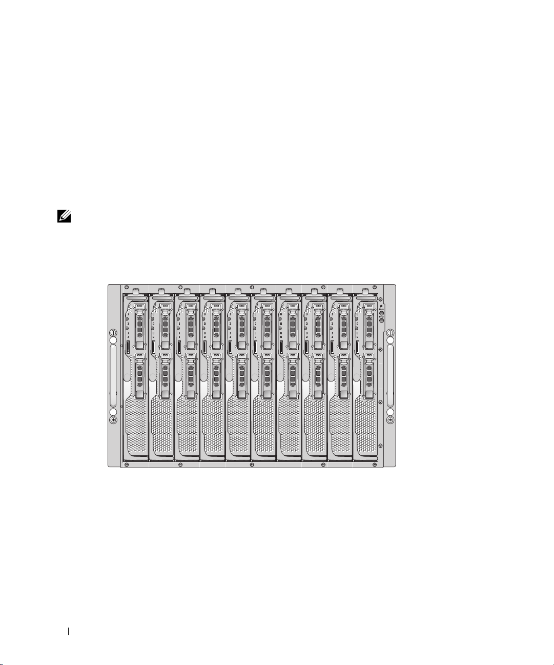
Your system can include up to ten server modules (or blades) (see Figure 1-1). Each server module
functions as an individual server encompassing up to two microprocessors, up to two hot-pluggable hard
drives, and up to eight memory modules. To function as a system, a server module is inserted into a
chassis that supports power supplies, fan modules, a management module (Dell
Controller/Modular Chassis [DRAC/MC]), a KVM switch module, and at least one I/O module for
network connectivity. The power supplies, fans, DRAC/MC, and I/O modules are shared resources of the
server modules in the chassis. In addition, your system may also ship with an optional external USB
diskette drive and an optional external USB CD drive, which you can use to set up and configure the
server modules.
NOTE: To ensure proper operation and cooling, all bays must be populated at all times with either a server module
or with a blank.
Figure 1-1. Server Modules
12345678910
™
Remote Access
This section describes the major hardware and software features of your system and provides information
about the indicators on the system's front and back panels. It also provides information about other
documents you may need when setting up your system and how to obtain technical assistance.
System Status Features
The chassis has front-panel control features including power and identification buttons and indicators
(see Figure 1-2). Press the power button to turn on the system; press and hold the power button to turn
off the system. Pressing the identification button activates the identification indicator on both the front
and back (on the KVM module) of the system. Table 1-1 shows the status features.
10 About Your System
Page 11
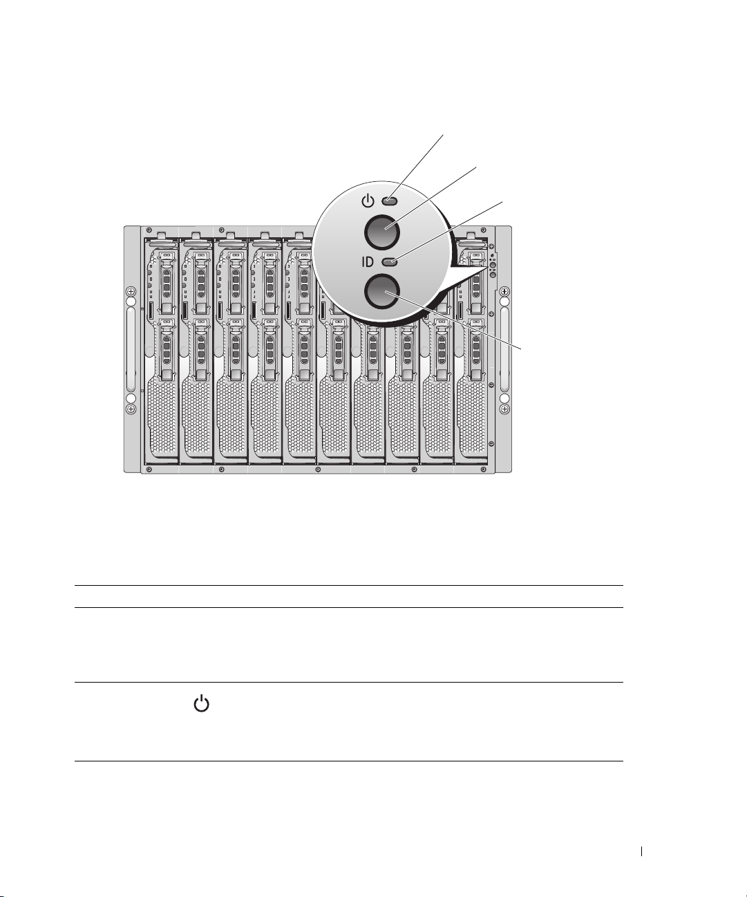
Figure 1-2. Front-Panel Control and Indicators
1
2
3
4
1 system power indicator 2 system power button 3 identification indicator
4 identification button
Table 1-1. System Status Features
Indicator Type Icon Indicator Indicator Code
System power
button
N/A None Turns the system on and off. Press to turn on the system.
Press and hold 10 seconds to turn off the system.
NOTE: The system power button controls power to all of the
server modules and I/O modules in the chassis.
System power
indicator
Identification
button
N/A None Turns on the identification indicators on both the front and
Off System does not have power.
Green System power is on.
Amber System is plugged in but is not turned on.
back (on the KVM switch module) of the chassis.
About Your System 11
Page 12
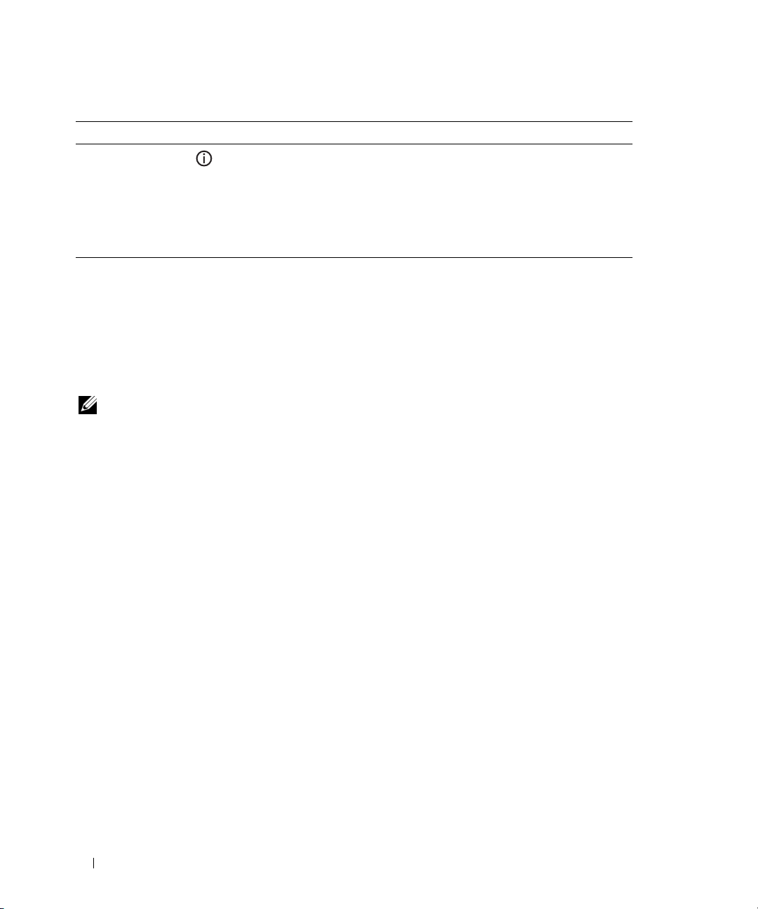
Table 1-1. System Status Features (continued)
Indicator Type Icon Indicator Indicator Code
Identification
indicator
Off Chassis is not being identified. This is the default.
Amber, slow
blinking
Amber, fast
blinking
Chassis is being identified. Either the front or back
identification button has been pressed. This indicator can
be turned off by pressing the identification button.
System error. Will stop blinking when the error is resolved.
Server Module Features
Each server module has one power button and one KVM module selection button on the front (see
Figure 1-3). The indicators include a power indicator, network link indicators, and a KVM module
indicator. The server module also has a custom port on the front of the module. Use the custom cable
included with your system to connect this port to two USB devices (for example, USB diskette drive,
USB CD drive, USB mouse) and to video.
NOTE: The USB devices can only be connected by using the custom cable supplied with the system.
12 About Your System
Page 13
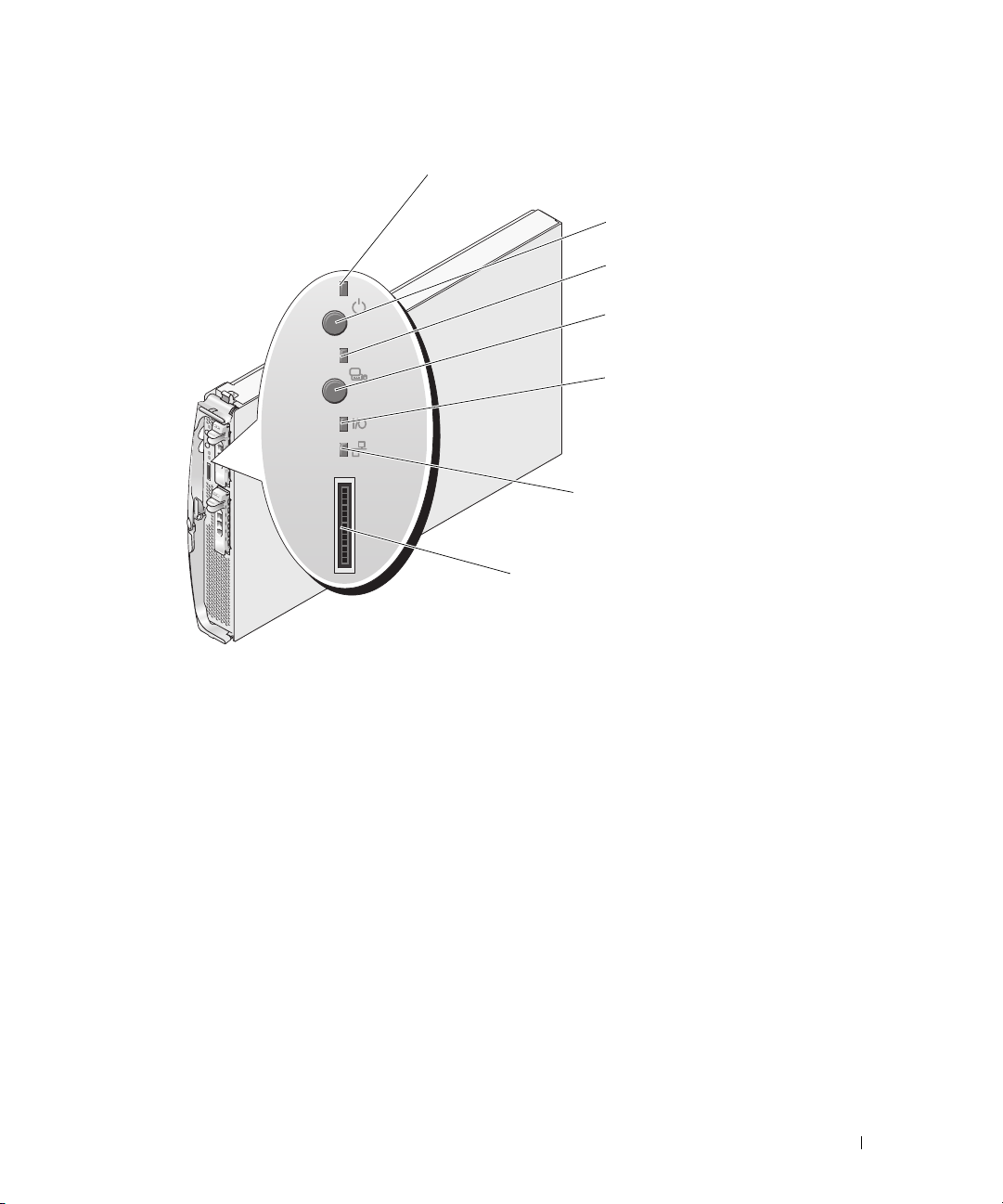
Figure 1-3. Server Module Indicators
1
2
3
4
5
6
7
1 server module power indicator 2 server module power button 3 KVM selection indicator
4 KVM selection button 5 daughter card status indicator 6 Ethernet network indicator
7 custom port (with custom
cable - USB [2] and video)
About Your System 13
Page 14
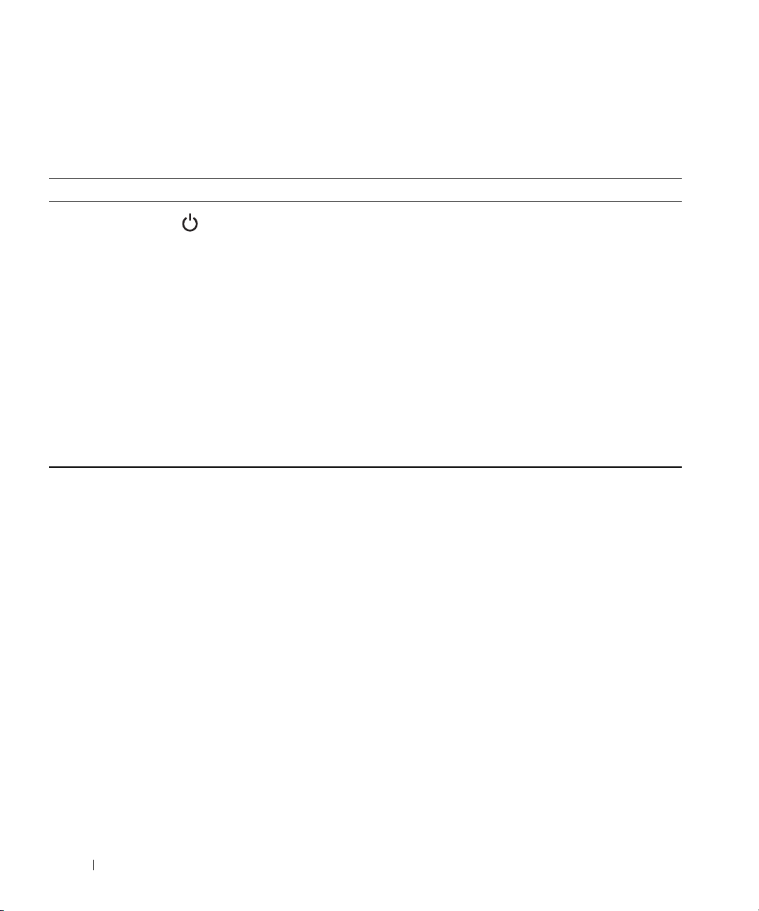
Table 1-2 provides information about the status indicators.
Table 1-2. Server Module Features and Indicators
Indicator Icon Activity Indicator Indicator Code
Server module
power indicator
Server module
power button
N/A None Turns server module power off and on.
Off Power is not available to the server module, the server
module is not turned on, or the server module is installed
incorrectly. For detailed information on installing a server
module, see "Server Modules" on page 73.
Green The module is turned on.
Green blinking fast The module power is on and there is a fault with the server
module.
Green blinking slowly The module power is on and the server module is being
remotely identified via the DRAC/MC.
Amber The module power is off, but the system power is on.
Amber blinking slowly The module power is off and the server module is being
remotely identified via the DRAC/MC.
Amber blinking fast The module power is off and there is a fault with the server
module.
• If you turn off the module using the power button and
the module is running an ACPI-compliant operating
system, the module can perform an orderly shutdown
before the power is turned off.
• If the module is not running an ACPI-compliant
operating system, power is turned off immediately after
the power button is pressed.
• Press and hold the button to turn off the server module
immediately.
The button is enabled in the System Setup program. When
disabled, you can only use the button to turn on the server
module.
14 About Your System
Page 15

Table 1-2. Server Module Features and Indicators (continued)
Indicator Icon Activity Indicator Indicator Code
KVM selection
indicator
KVM selection
button
Daughter card
status indicator
(Infiniband card
installed)
Daughter card
status indicator
(Fibre channel
daughter card
installed)
Daughter card
status indicator
(Gb Ethernet
daughter card
installed)
Daughter card
status indicator
(TOE NIC
daughter card
installed)
N/A None Selects the server module for use with the KVM located on
I/O Off Daughter card is not installed.
I/O Off Daughter card is not installed.
I/O Off Daughter card is not installed.
I/O Off Daughter card is not installed.
Off The server module is not selected by the KVM.
Green The server module is selected for the KVM.
Amber blinking The server module is not selected by the KVM and a power
fault exists.
Green/amber blinking The server module is selected for the KVM and a power fault
exists.
the back of the system. See "Avocent Analog KVM Switch
Module" on page 22 for information on selecting a server
module by using the keyboard.
Green Infiniband daughter card is installed, but no traffic is
detected.
Green blinking Infiniband daughter card is present and data transfers are
occurring.
Green A link exists.
Green blinking Fibre channel daughter-card data transfers are occurring.
Green A link exists.
Green blinking Gb Ethernet daughter-card data transfers are occurring.
Green A link exists.
Green blinking TOE NIC daughter card is installed and data transfers are
occurring.
About Your System 15
Page 16
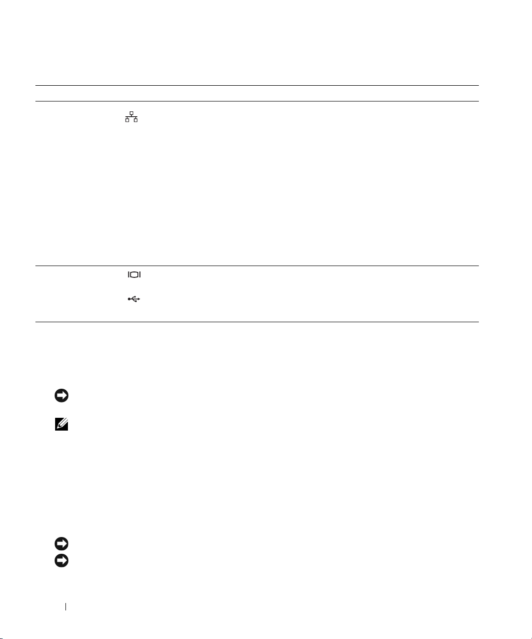
Table 1-2. Server Module Features and Indicators (continued)
Indicator Icon Activity Indicator Indicator Code
Network indicators Off Indicates that the server module does not have a link to the
Ethernet switch or pass-through module.
Green on Indicates that the server module has a valid link to the
network switch module.
Green blinking Indicates network activity between the server module and
the network switch module.
NOTE: External network activity is not reported by this
indicator.
NOTE: This network indicator may also blink green due to
systems management activity if you use the integrated NIC to
remotely access your system’s Baseboard Management
Controller (BMC). See "Baseboard Management Controller
Configuration" on page 54.
USB/video
connector
None Use the custom cable to connect external USB devices and
video to the server module.
Using USB Diskette or USB CD Drives
Each server module has a USB port on the front of the server module which allows you to connect a
custom cable for a diskette drive or USB CD drive. The USB drives are used to configure the server
module.
NOTICE: The system supports only Dell-branded USB 1.1 or USB 2.0 drives. The drive must be horizontal and level
to operate properly.
NOTE: If the drive must be designated as the boot drive, connect the USB drive, restart the system, then enter the
System Setup Program and set the drive as first in the boot sequence (see "Using the System Setup Program" on
page 43). The USB device will be displayed in the boot order setup screen only if it is attached to the system before
you run the System Setup program.
Hard-Drive Features
Each server module supports one or two hot-pluggable SAS hard drives, or one or two hot-pluggable
SATA hard drives. See Figure 1-4 and Table 1-3 for information on the hard-drive indicators. Different
patterns are displayed as drive events occur in the system.
NOTICE: Each server module must have a hard drive or a hard-drive blank installed in each hard-drive bay.
NOTICE: You cannot install a SAS drive and a SATA drive within a given server module (blade). However, you can
install server modules (blades) with SAS drives and server modules with SATA drives in the same server enclosure.
16 About Your System
Page 17
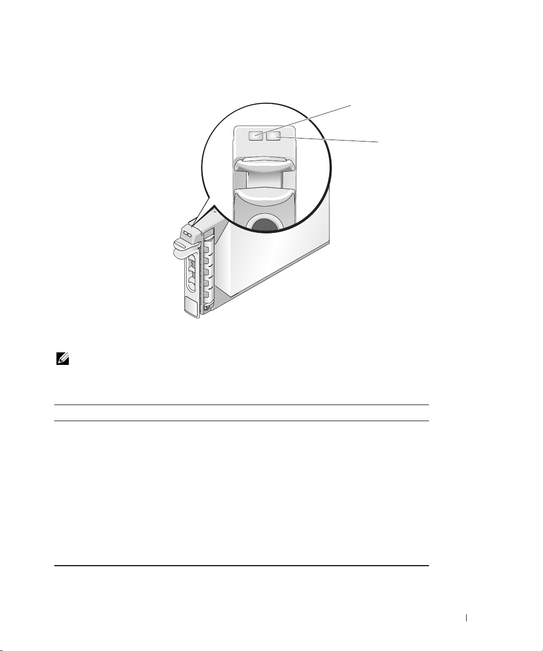
Figure 1-4. Hard-Drive Features and Indicators
1 drive activity indicator 2 drive status indicator
NOTE: The hard-drive status indicator is only functional for RAID hard drive configurations.
For non-RAID configurations, only the drive-activity indicator is active.
1
2
Table 1-3. Hard-Drive Status Indicator Patterns (RAID Configurations Only)
Status Indicator State Indicator Code
Off
Green Drive is online.
Green, blinking slowly Drive is rebuilding.
Green, blinking quickly Drive is being identified.
Amber Drive has failed or has an error. See "Troubleshooting Hard
Amber blinking slowly,
green blinking slowly, then off
• Drive is ready for removal.
• Drive bay is empty.
• Power is off to the server module.
Drives" on page 113.
The drive has reported a predictive failure event, and should
be replaced.
About Your System 17
Page 18
Back-Panel Features
The back of the chassis supports four I/O module bays, the DRAC/MC, fan modules, and power supply
modules. Figure 1-5 shows a sample configuration and the numbering for the bays. Table 1-4 provides
information about the back-panel features.
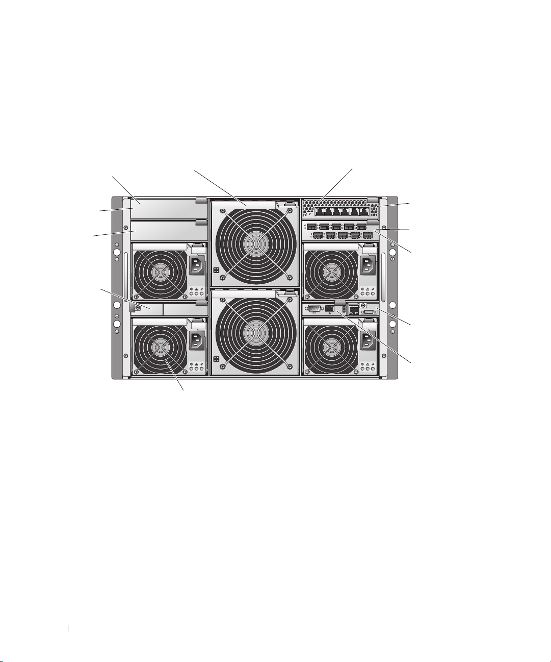
Figure 1-5. Back-Panel Features
1
12
11
10
1 I/O bay 2 2 fan modules (2) 3 PowerConnect 5316M
4 I/O bay 1 5 Fibre Channel pass-through
7 KVM module 8 DRAC/MC module 9 power supply modules (4)
10 blanks (2) 11 I/O bay 4 12 blanks (2)
2
9
module
3
34
12
Ethernet switch module
6 I/O bay 3
4
5
6
7
8
18 About Your System
Page 19

Table 1-4. Back-Panel Features and Indicators
Component Indicator Description
Power supply modules Provide information about power status (see "Power Supply Indicator Codes" on
page 20).
Fan modules Provide information about status of the system fans (see "Fan Module Indicators"
on page 21).
KVM module Provides information about the KVM module (see "KVM Modules" on page 22).
DRAC/MC module Provides information about system status, system management status, and port
status (see "DRAC/MC Module" on page 26).
PowerConnect™ 5316M
Ethernet switch module
Fibre Channel pass-through
module
Fibre Channel switch module Provides information about the Fibre Channel network status (see "Fibre
Infiniband pass-through
module
Gb pass-through module Provides information about the network status (see "Gb Ethernet Pass-through
Provides information about the 10/100/1000 BASE-T network status (see
"PowerConnect 5316M Ethernet Switch Module" on page 29).
Provides information about the Fibre Channel network status (see "Fibre
Channel Pass-Through Module" on page 31).
Channel Switch Module" on page 32).
Provides information about the Infiniband network status (see "Infiniband Passthrough Module" on page 32).
Module" on page 33).
Power Supply Indicator
Each hot-pluggable power supply has indicators that provide information about power status, fault, and
the presence of AC power (see Figure 1-6). Table 1-5 lists the power supply indicator codes.
NOTE: Only 2100-W power supply modules are supported on your system. The 2100-W power supply modules
require 180–240 V input from a PDU capable of providing AC current up to 29.2 A at 180 V input. If the power supply
modules are plugged into 110-V electrical outlets, the system will not power up.
About Your System 19
Page 20
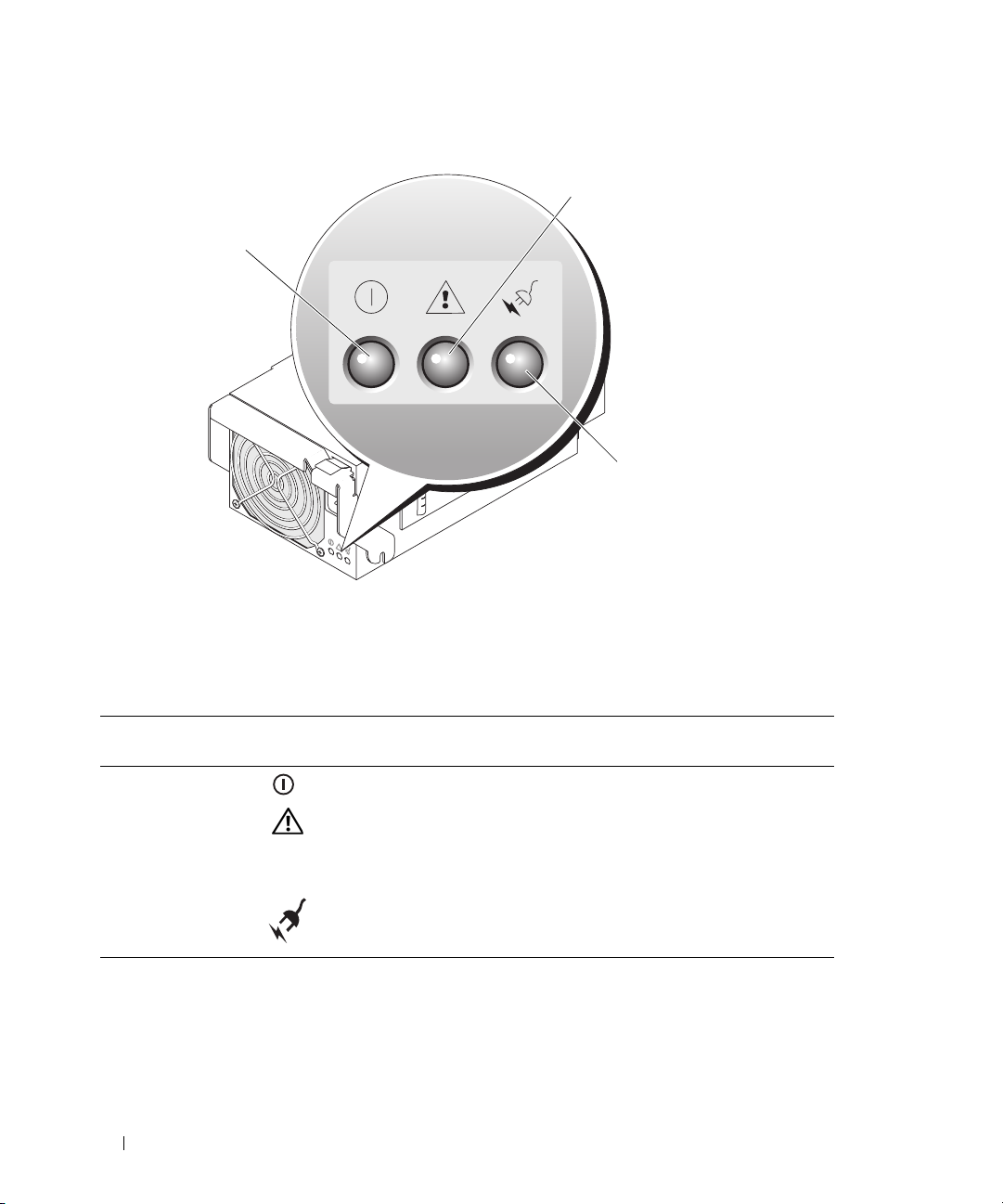
Figure 1-6. Power Supply Indicators
1
3
2
1 fault indicator 2 AC power present indicator 3 DC power indicator
Table 1-5. Power Supply Indicator Codes
Indicator Icon Activity
Indicator
DC power indicator Green The power supply is operational.
Fault indicator Amber The power supply is in a fault condition. The fault
AC power present
indicator
Green AC power is present at the power supply and the system
Indicator Code
condition can result from either a failed power supply
or a failed fan within the power supply. See "Power
Supply Modules" on page 58.
is connected to an AC power source.
20 About Your System
Page 21
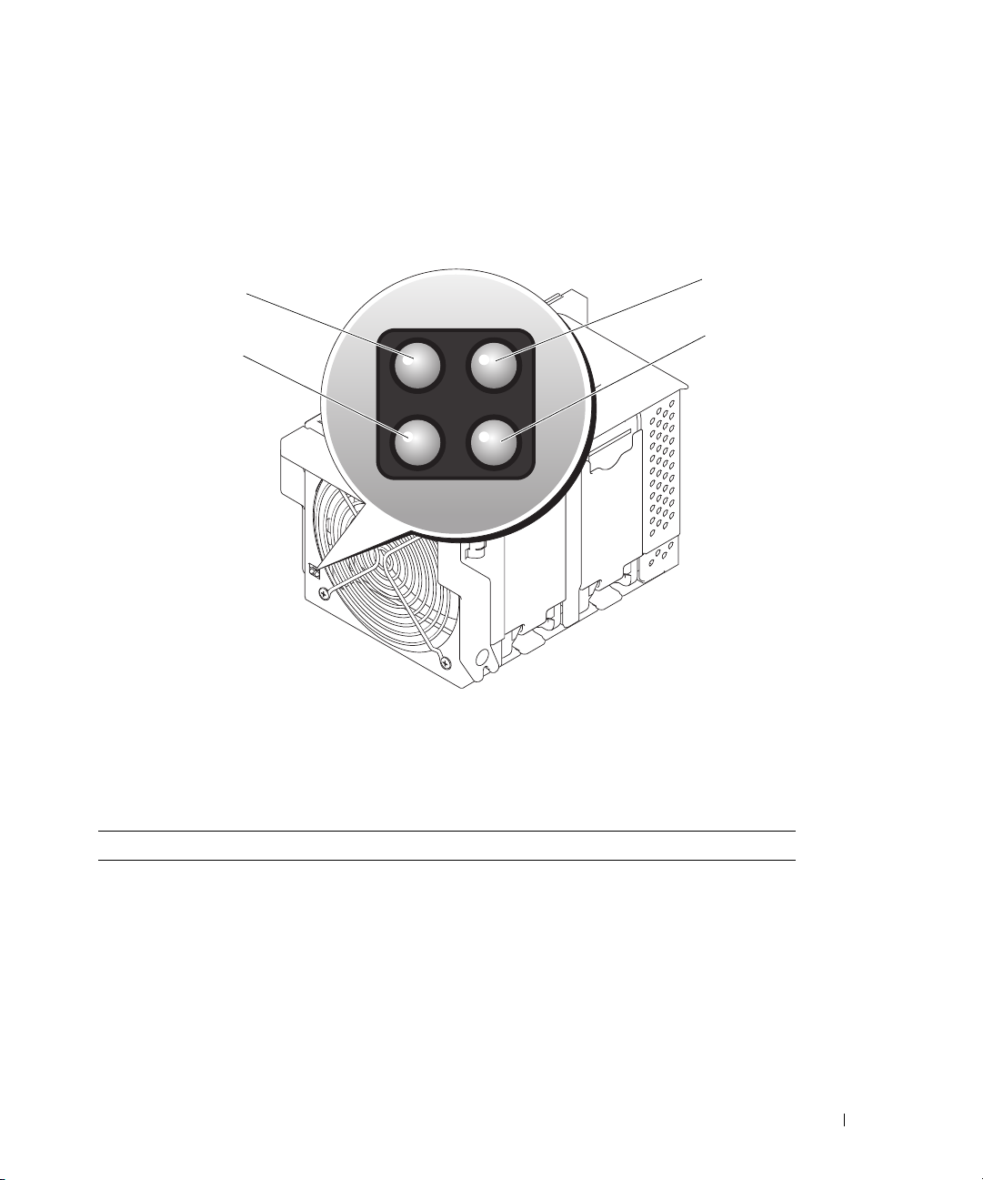
Fan Module Indicators
Each hot-pluggable fan module contains two redundant fans (see Figure 1-7). Table 1-6 lists the fan
indicator codes.
Figure 1-7. Fan Module Indicators
1
4
1 fan 1 fault indicator 2 fan 1 present indicator 3 fan 2 present indicator
4 fan 2 fault indicator
2
3
Table 1-6. Fan Module Indicator Codes
Indicator Activity Indicator Indicator Code
Fan 1 present indicator Off Fan 1 is not installed.
Green Fan 1 is installed.
Fan 1 fault indicator Off Fan 1 is operating normally.
Amber Fan 1 has failed. See "Fan Modules" on page 59.
Fan 2 present indicator Off Fan 2 is not installed.
Green Fan 2 is installed.
About Your System 21
Page 22

Table 1-6. Fan Module Indicator Codes (continued)
Indicator Activity Indicator Indicator Code
Fan 2 fault indicator Off Fan 2 is operating normally.
Amber Fan 2 has failed. See "Fan Modules" on page 59.
KVM Modules
Your system includes one of the KVM modules described in this section:
• Avocent Analog KVM switch module (standard)
• Avocent Digital Access KVM switch module (optional)
NOTE: Earlier versions of KVM modules are not supported on your system.
Avocent Analog KVM Switch Module
The Avocent Analog KVM switch module provides a custom connection for a keyboard, video (monitor),
and mouse to monitor a server module. (You must use the custom cable provided with your system to
connect the KVM to the external devices.)
NOTE: Your system has two custom cables—one that connects to the front of the server module to connect two
USB devices and video, and a second cable that connects to the KVM to provide two PS/2 connections and a video
connection. The cables are not interchangeable. It is recommended that you keep these custom cables available.
The switch module also provides an Analog Console Interface (ACI) port, which allows you to connect a
server module via Cat5 cabling to an external device such as the Dell 2161DS Digital console switch or
Dell 180AS/2160AS analog console switches, without the need for a Server Interface Pod (SIP.)
NOTE: Although the ACI port is an RJ-45 connector and uses Cat5 cabling, it is not an Ethernet network interface
port. It is only used for connection to external KVM switches with Analog Rack Interface (ARI) ports.
NOTE: The ACI port can only be used to connect to ARI ports on Dell console switches. To connect to other types or
brands of switches, including Avocent switches, you must connect to the switch’s PS2 and video ports using the
proprietary dongle provided with that switch.
22 About Your System
Page 23
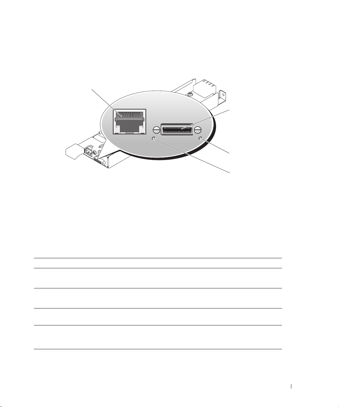
Figure 1-8 shows the external features on the Avocent Analog KVM switch module.
Figure 1-8. Avocent Analog KVM Switch Module
1
2
3
4
1 ACI port 2 custom connector for custom
cable (PS/2 [2] and video)
4 power indicator
3 identification indicator
The Avocent Analog KVM switch module also includes an identification indicator (see Figure 1-8).
Table 1-7 describes the indicators and features on this switch module.
Table 1-7. Avocent Analog KVM Switch Module Indicators and Features
Feature Activity Indicator Indicator Code
Identification
indicator
Power indicator Off KVM switch does not have power.
Custom
connector
ACI port None Allows connection of one or more servers to a Dell console
Off Chassis is not being identified.
Amber blinking Chassis is being identified.
Green KVM switch has power.
None Allows two PS/2 and one video device to be connected to the
system.
switch with an Analog Rack Interface (ARI) port, such as a
digital or analog console switch.
About Your System 23
Page 24

Avocent Digital Access KVM Switch Module
The optional Avocent Digital Access KVM switch module allows you to configure and manage the server
modules through a single keyboard, monitor and mouse. You select server modules using the On-Screen
Configuration and Reporting (OSCAR) graphical user interface (GUI).
The Avocent Digital Access KVM switch module includes the following features:
• Analog KVM switching
This switch can be used as an Analog switch, allowing local KVM switching through direct connection
of a keyboard, monitor and mouse; or tiered into external analog KVM switches. This switch uses the
same OSCAR interface as the Avocent Analog KVM switch to switch between server modules.
The Digital Access KVM switch provides a custom connector which brings out PS2/video ports. These
ports can be directly connected to a keyboard, monitor, and mouse, or tiered into an external analog
KVM switch with KVM ports. If you are connecting the Digital Access KVM switch to an external
KVM switch using Cat5 connectors/ACI ports, that switch’s dongle (PS2/video to Cat5) is required.
NOTE: The Avocent Digital Access KVM module differs from the Avocent Analog KVM module in that the
Digital Access KVM switch module does not have an ACI port; it has an Ethernet network interface.
• Remote control of Virtual Media and virtual KVM
After connecting to your network using the switch’s Ethernet connection, use the system’s DRAC/MC
GUI to select Media and/or console and which server module to connect to.
NOTE: You must connect the switch’s Ethernet port into the same network as the DRAC/MC port.
You can then use the switch’s Virtual Media and virtual KVM features:
– Virtual Media – Using this feature, you can remotely map local drives on a management
workstation to the server module, or boot a server module to a remote diskette, optical drive, or
USB key. For example, you can remotely perform operating system installation, operating system
recovery, BIOS updates, and other functions.
– Virtual KVM – You can remotely control the server modules from any location, using the digital
KVM and an OS-independent graphical console.
24 About Your System
Page 25
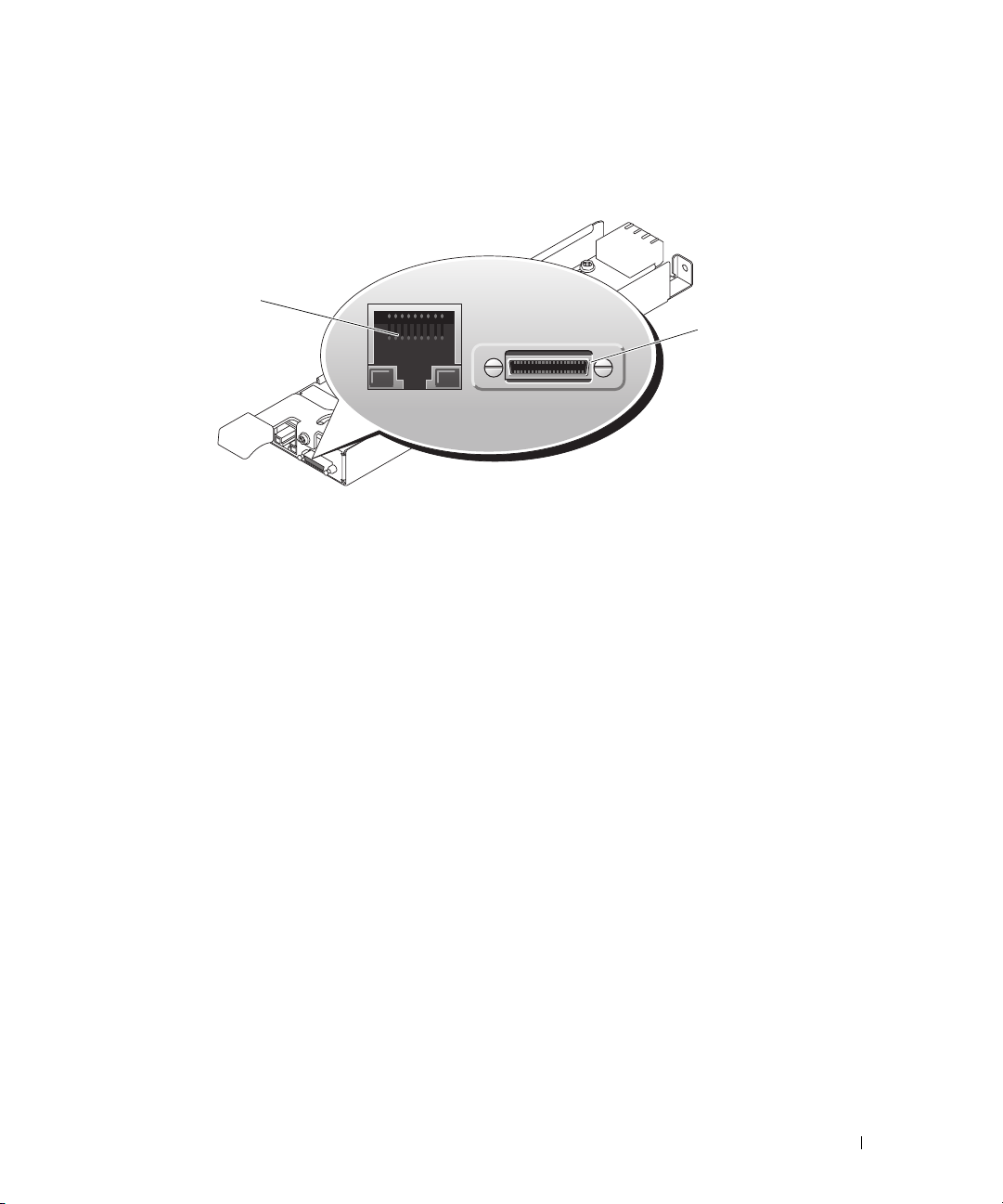
Figure 1-9 shows the external features of the Avocent Digital Access KVM switch module.
Figure 1-9. Avocent Digital Access KVM Switch Module
1
2
1 RJ-45 connector (Ethernet
interface)
2 custom connector (for custom
KVM cable - PS/2 [2] and
video)
About Your System 25
Page 26
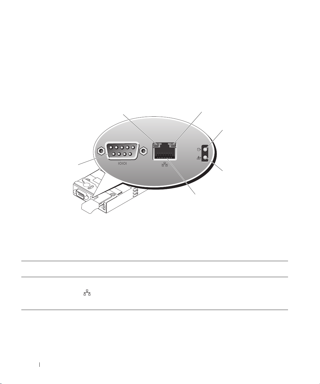
DRAC/MC Module
2
The DRAC/MC provides serial and Ethernet management ports, a status indicator when redundant
DRAC/MCs are installed (when available), and status indicators for the DRAC/MC and for the link to
the system's onboard network interface controller (see Figure 1-10). See the documentation for the
DRAC/MC module for specific information on serial port redirection of server modules and switches.
Table 1-8 provides information about the status indicators.
Figure 1-10. DRAC/MC Module Features
1
3
6
4
5
1 link indicator 2 activity indicator 3 primary/secondary indicator
4 fault indicator 5 network interface controller 6 serial connector
Table 1-8. DRAC/MC Module Indicators
Indicator Type Icon Activity
Indicator
Network interface
controller link
indicator
Network interface
controller activity
indicator
Off LAN is not linked.
Green LAN is linked.
Off LAN is not active.
Amber blinking Indicates that the system DRAC/MC and the LAN are
26 About Your System
Indicator Code
communicating.
Page 27
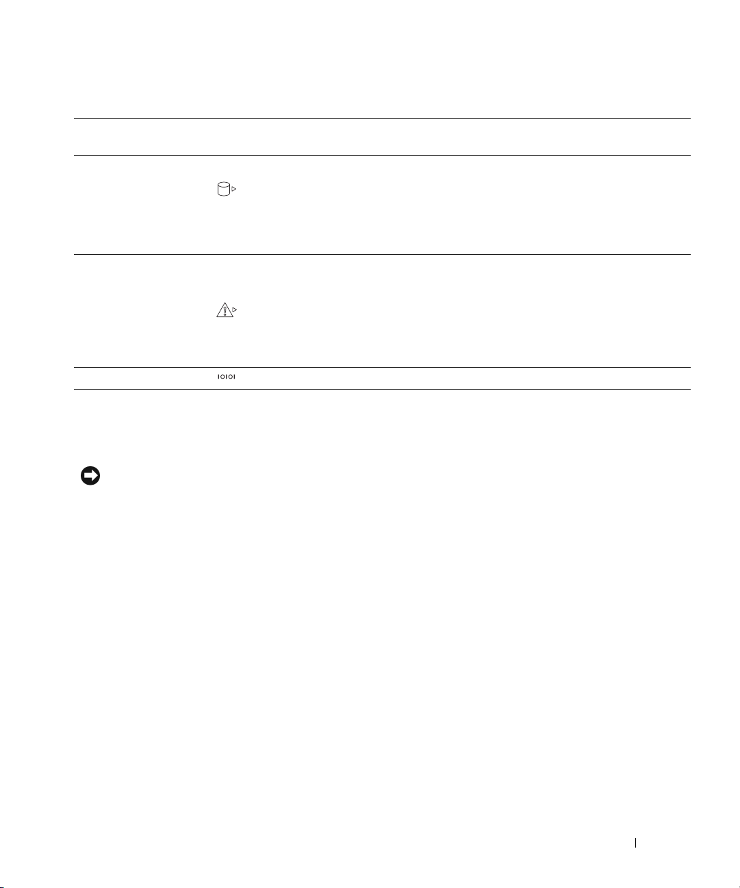
Table 1-8. DRAC/MC Module Indicators (continued)
Indicator Type Icon Activity
Indicator
Primary/secondary
indicator
Fault indicator Off The DRAC/MC is operating normally.
Serial connector None Used for a serial connection with a null modem cable.
Off The DRAC/MC is a backup for the master DRAC/MC.
Green The DRAC/MC is active for system management.
Green blinking The DRAC/MC is in special or manufacturing mode.
Amber In a single (nonredundant) configuration, this DRAC/MC failed.
Amber blinking In a dual (redundant) configuration (when available), this
Indicator Code
NOTE: For information on availability of dual (redundant)
configurations for the DRAC/MC, see www.dell.com.
See "DRAC/MC Module" on page 61.
DRAC/MC failed. See "DRAC/MC Module" on page 61.
Important I/O Configuration Considerations
Insure that you read the DRAC/MC module’s readme.txt file. It contains updated information, including
system indicator behavior in certain conditions.
CAUTION: Data loss can result if you perform certain actions on a system in which the I/O bays have not been
configured correctly. Specifically, bay 2 should have an I/O module installed only if a module of the same fabric
type is present in bay 1, and bay 4 should have an I/O module installed only if a module of the same fabric type is
present in bay 3. Except in these cases (or in a case where you temporarily need to swap a failed I/O module in
bay 1 or 3), bays 2 and 4 should be unoccupied.
Unless your system is configured according to these guidelines, do not perform any of the following actions:
•
Upgrade DRAC/MC firmware
•
Issue a software reset command for a DRAC/MC, such as racadm racreset
•
Reseat a DRAC/MC module
•
Cause a DRAC/MC failover event, such as removing the network cable from the primary DRAC/MC, or rebooting
a switch that the DRAC/MC cable is connected to
Performing any of these actions will power off and stop traffic on the bay 2 or bay 4 I/O module, resulting in data loss.
When initiated, the DRAC/MC firmware algorithm must find a module in bay 1 before bay 2 and a
module in bay 3 before bay 4. Otherwise, the module in bay 2 or bay 4 will be powered off if you perform
a firmware upgrade procedure on the DRAC/MC, cause a DRAC/MC failover, or reset the DRAC/MC.
See the current Dell Remote Access Controller/Modular Chassis User's Guide at support.dell.com for
more information about configuring your DRAC/MC system.
About Your System 27
Page 28

DRAC/MC Firmware Requirements
The minimum DRAC/MC firmware requirement for your system is version 1.3 or later. If you are adding
a second DRAC/MC module with version 1.0 to support redundancy, you must upgrade the module’s
firmware to version 1.1, then upgrade the firmware to version 1.3 (or later).
NOTE: A DRAC/MC module’s firmware version is displayed on its web-based GUI or by typing the command
getsysinfo or racadm getsysinfo.
See the latest Dell Remote Access Controller/Modular Chassis User's Guide at support.dell.com for more
information about firmware updates and installing redundant DRAC/MC modules. This guide also
provides complete instructions on how to set up and operate that version of the module.
I/O Connectivity
The system offers several options for connectivity through a combination of embedded Ethernet
controllers, optional I/O daughter cards on the server module, and chassis I/O modules in the rear of the
chassis. An I/O module's green system/diagnostic indicator is off when the module is properly operating
or is off and blinks when the module is not properly operating.
Guidelines for Installing Connectivity Modules
The following guidelines must be used when populating I/O modules. See Figure 1-5 for I/O bay
locations.
• Insert a connectivity module into I/O bay 1 before installing a connectivity module into I/O bay 2.
Ensure that the connectivity modules installed in I/O bays 1 and 2 are of the same fabric type.
• Insert a connectivity module into I/O bay 3 before installing a connectivity module into I/O bay 4.
Ensure that the connectivity modules installed in I/O bays 3 and 4 are of the same fabric type.
• I/O bay 3 connects to port 1 on the daughter card (optional) installed in the server module.
– This bay must be populated if there is a daughter card installed in the server module.
– The type of I/O module installed in this bay must match the type of daughter card installed in the
server module. For example, a Fibre Channel I/O module requires that a Fibre Channel daughter
card be installed in the server module.
28 About Your System
Page 29

Table 1-9 lists the valid I/O module configurations. See Figure 1-5 for I/O bay locations.
Table 1-9. Valid I/O Module Configurations
Network Controller Bay IO/1 Bay IO/2 Bay IO/3 Bay IO/4
Server Module
Embedded NIC 1
Server Module
Embedded NIC 2
Fibre Channel
Daughter Card Port 1
Fibre Channel
Daughter Card Port 2
Gb Ethernet Daughter
Card Port 1
Gb Ethernet Daughter
Card Port 2
Infiniband Daughter
Card
Ethernet switch
module or passthrough module
N/A Ethernet switch
N/A N/A Fibre channel
N/A N/A N/A Fibre channel
N/A N/A Ethernet switch
N/A N/A Ethernet switch
N/A N/A Infiniband module
N/A N/A N/A
N/A N/A
module or passthrough module
N/A
switch or passthrough module
switch or pass-
through module
module or passthrough module
module or pass-
through module
Infiniband module
(either or both
bays)
(either or both
bays)
PowerConnect 5316M Ethernet Switch Module
The PowerConnect 5316M Ethernet switch module is a 16-port switch with 6 uplinks and 10 downlinks
(see Figure 1-11). The uplinks connect to the external Ethernet network and operate at 1/2/4 Gb. The
downlinks connect to the embedded Ethernet controller on the server module and operate at 1 Gb only.
The PowerConnect 5316M Ethernet switch module is hot-pluggable. To provide connectivity into
separate Ethernet networks, two switch modules can be installed in bays I/O 1 and I/O 2 (see Figure 1-5).
I/O bays 3 and 4 require that you install a Gb Ethernet daughter card in the server module. If redundancy
is not required, the switch module must be installed in I/O 1 bay. The switch module has an internal
serial port that communicates with the DRAC/MC module. Table 1-10 lists the indicators on each switch
module. For additional information about the PowerConnect 5316M Ethernet switch module, see the
documentation that shipped with the module.
About Your System 29
Page 30
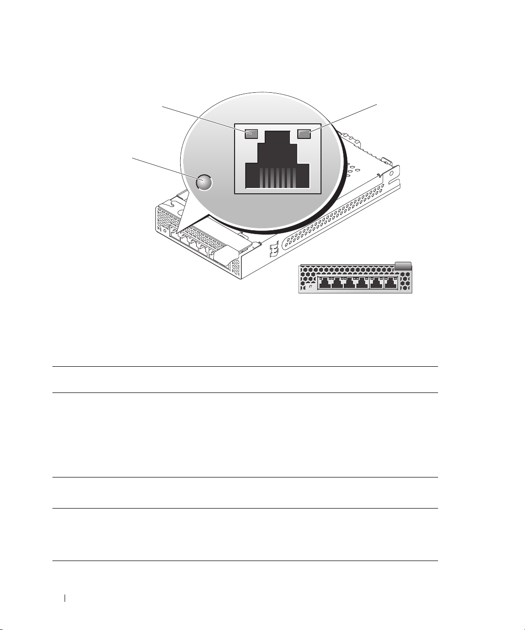
Figure 1-11. PowerConnect 5316M Ethernet Switch Module Indicators and Features
1
3
1 speed/link activity indicator 2 duplex mode indicator 3 system/diagnostic indicator
Table 1-10. PowerConnect 5316M Ethernet Switch Module Indicators
Indicator Type Activity
Indicator
Speed/link activity
indicator (bicolor)
Off Not connected.
Green The port is connected to a valid link partner on the network.
Green blinking Network data is being sent or received at 1 Gb.
Amber The port is connected to a valid link partner on the network.
Amber blinking Network data is being sent or received at 10 Mb or 100 Mb.
Indicator Code
2
161514131211
Duplex mode
indicator
System/diagnostic
indicator
Green The port is operating at full duplex mode.
Off The port is operating at half duplex mode.
Green blinking Module is being powered down by the DRAC/MC controller
Off Module is operating normally.
30 About Your System
due to an I/O module mismatch. See "Guidelines for Installing
Connectivity Modules" on page 28.
Page 31

Fibre Channel Pass-Through Module
The Fibre Channel pass-through module provides a bypass connection between the Fibre Channel
daughter card in the server module and optical transceivers for direct connection into a Fibre Channel
switch or a storage array. (see Figure 1-12). The Fibre Channel pass-through modules are hot-pluggable.
The Fibre Channel pass-through module in I/O bay 3 connects to port 1 on the optional Fibre Channel
daughter card installed in a server module. The Fibre Channel pass-through module in I/O bay 4
connects to port 2 on the optional Fibre Channel daughter card installed in a server module. To provide
redundancy, both I/O bay 3 and I/O bay 4 must have Fibre Channel pass-through modules installed.
Table 1-11 lists the functionality of the Fibre Channel pass-through module indicators. For additional
information on installing this module, see "Chassis I/O Module" on page 70.
NOTE: The Fibre Channel pass-through module includes Short Wave Small Form Factor Pluggable (SFP) optical
transceivers. To ensure proper functionality, use only the SFPs provided with this module.
Figure 1-12. Fibre Channel Pass-through Module Indicators and Features
1
2
3
13579
246810
1 SFP Fibre Channel connector 2 green indicator 3 amber indicator
About Your System 31
Page 32

Table 1-11. Fibre Channel Pass-Through Module Indicators
Indicator Type Activity
Indicator
Fibre Channel
indicator
(green/amber)
Off Power is off to the system.
Green/amber System has power.
Green/off Fibre Channel connection is online.
Off/amber The port is connected to a valid link partner on the network.
Off/flashing (twice
per second)
Indicator Code
Connection has lost synchronization.
Fibre Channel Switch Module
You can install one or two hot-pluggable Fibre Channel switch modules in I/O bay 3 and I/O bay 4,
beginning with I/O bay 3. You must also install a Fibre Channel HBA daughter card in the server module.
The Fibre Channel switch module includes four external autosensing Fibre Channel ports numbered 10
through 13, 10 internal ports, and one Ethernet port with an RJ-45 connector. All the external ports operate
at 1 Gb/sec, 2 Gb/sec, or 4 Gb/sec.
See the documentation for your particular Fibre Channel switch module for the functionality and
location of the switch module indicators. For general information on installing this module, see "Chassis
I/O Module" on page 70.
NOTE: The Fibre Channel switch module includes Short Wave Small Form Factor Pluggable (SFP) optical
transceivers. To ensure proper functionality, use only SFPs provided with this module.
Infiniband Pass-through Module
The Infiniband pass-through module provides a bypass connection between an optional Infiniband Host
Channel Adapter (HCA) daughter card in the server module and 4x Infiniband Transceivers for direct
connection to an Infiniband switch. The Infiniband pass-through modules are hot-pluggable. To provide
redundancy, both I/O bay 3 and I/O bay 4 must have Infiniband pass-through modules installed. In this
configuration, the module in I/O bay 3 connects to port 1 on the Infiniband HCA daughter card; the
Infiniband pass-through module in I/O bay 4 connects to port 2 on the Infiniband HCA daughter card.
NOTE: The Infiniband pass-through module uses small form factor 4x Infiniband connectors. To ensure proper
functionality, use only cables provided with the module.
NOTE: If you require service, technical support, or parts replacement for your Topspin Infiniband product, contact
Topspin Support Services directly at 1-800-499-1473 or through www.topspin.com.
32 About Your System
Page 33

Gb Ethernet Pass-through Module
The Gb Ethernet pass-through module has 10 RJ45 ports. When installed in I/O 1 bay or I/O 2 bay, the
Gb Ethernet pass-through module provides a connection between the server module and an external Gb
Ethernet device. When installed in the I/O 3 bay or I/O 4 bay, the Gb Ethernet pass-through module
provides a connection between the optional internal Gb Ethernet daughter card in the server module,
providing a direct connection into an external Gb Ethernet device (see Figure 1-13). The Gb Ethernet
pass-through modules are hot-pluggable. The Gb Ethernet pass-through module in I/O bay 3 connects to
the optional Gb Ethernet daughter card installed in a server module. The Gb Ethernet pass-through
module in I/O bay 4 connects to port 2 on the optional Gb Ethernet daughter card installed in a server
module. Table 1-12 lists the functionality of the Gb Ethernet pass-through module indicators. For
additional information on installing this module, see "Chassis I/O Module" on page 70.
NOTE: Only connect the Gb Ethernet module to 1000-Mb external switch ports. Do not use this module with 10-Mb
or 100-Mb external switch ports.
Figure 1-13. Gb Pass-through Module Indicators and Features
1
5
4
1 activity indicator 2 link indicator 3 status indicator
4 link indicator 5 activity indicator
NOTE: Connectors on the Gb pass-through module correspond directly to the server module number. For example,
server module 5 is connected to port 5 on the Gb pass-through module.
2
3
13579
246810
About Your System 33
Page 34
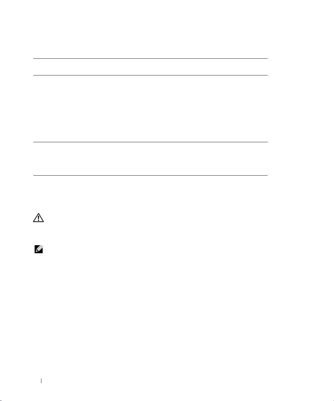
Table 1-12. Gb Pass-through Module Indicators
Indicator Type Activity
Indicator
Link
indicator/activity
indicator
Status indicator Green Module is operating correctly.
Green/amber
blinking
Green/off The Gb Ethernet connector is linked to the server module
Off/amber blinking The Gb Ethernet connector is not linked to the server
Off/off The Gb Ethernet connector is not linked to the server
Green blinking Module is being powered down by the DRAC/MC controller
Indicator Code
The Gb Ethernet connector is linked to the server module
and there is network activity
and there is no network activity.
module and there is network activity.
module and there is no network activity.
due to an I/O module mismatch. See "Guidelines for
Installing Connectivity Modules" on page 28.
Server Module Messages
System messages appear on the screen to notify you of a possible problem with the system. Table 1-13
lists the system messages that can occur and the probable cause and corrective action for each message.
CAUTION: Many repairs may only be done by a certified service technician. You should only perform
troubleshooting and simple repairs as authorized in your product documentation, or as directed by the online or
telephone service and support team. Damage due to servicing that is not authorized by Dell is not covered by your
warranty. Read and follow the safety instructions that came with the product.
NOTE: If you receive a system message that is not listed in Table 1-13, check the documentation for the application
that is running when the message appears or the operating system's documentation for an explanation of the
message and recommended action.
34 About Your System
Page 35

Table 1-13. Server Module Messages
Message Causes Corrective Actions
Alert: DIMM_
must be populated with a
matched set of DIMMs if
more than 1 DIMM is
present. The following
memory DIMMs have been
disabled:
Alert! Redundant memory
disabled!. Memory
configuration does not
support redundant memory
Alert! Unsupported memory,
incomplete sets, or
unmatched sets. The
following memory DIMMs
have been disabled:
Caution! NVRAM_CLR jumper
is installed on system
board.
CPUs with different cache
sizes detected.
Decreasing available
memory
DIMMs should be installed
in pairs. Pairs must be
matched in size, speed,
and technology.
n
and DIMM_n
Ensure that the memory modules are
installed in matched pairs. See "General
Memory Module Installation
Guidelines" on page 78.
The installed memory configuration
does not support redundant memory.
The installed memory configuration is
invalid.
NVRAM_CLR switch is set to "on." Set the NVRAM_CLR switch to "off."
Mismatched processors are installed. Install a correct version of the
Faulty or improperly installed memory
modules.
Mismatched or unmatched DIMMs
installed; faulty or improperly
installed memory modules. The
system will operate in a degraded
mode with reduced ECC protection.
Only memory installed in channel 0
will be accessible.
Install a memory configuration that
supports redundant memory. See
"General Memory Module Installation
Guidelines" on page 78.
Disable the Redundant Memory option
in the System Setup program. See
"Using the System Setup Program" on
page 43.
Add, move, or remove memory modules
to achieve a configuration supported by
the system. See "General Memory
Module Installation Guidelines" on
page 78.
See Figure 6-2 for the jumper location.
microprocessor so that both
microprocessors have the same cache
size. See "Processors" on page 84.
Ensure that all memory modules are
properly installed. See "Troubleshooting
Server Module Memory" on page 112.
Ensure that all pairs of memory modules
are of the same type and size and that
they are properly installed. See "General
Memory Module Installation
Guidelines" on page 78. If the problem
persists, see "Troubleshooting Server
Module Memory" on page 112.
About Your System 35
Page 36

Table 1-13. Server Module Messages (continued)
Message Causes Corrective Actions
DIMMs must be populated in
sequential order beginning
with slot 1. The following
DIMM is electrically
x
isolated: DIMM
DIMM pairs must be matched
in size, speed, and
technology. The following
DIMM pair is mismatched:
x
DIMM
Diskette drive
failure
Diskette read failure Faulty or improperly inserted diskette. Replace the diskette.
Diskette subsystem reset
failed
Drive not ready Diskette missing or improperly
Error: Incorrect memory
configuration. DIMMs must
be installed in pairs of
matched memory size,
speed, and technology.
and DIMM
.
y.
n
seek
The specified DIMM is inaccessible to
the system due to its location.
DIMMs must be populated in
sequential order, beginning with
slot 1.
Mismatched or unmatched DIMMs
installed; faulty or improperly seated
memory modules.
Incorrect configuration settings in
System Setup program.
Faulty or improperly connected
diskette or optical drive to the custom
cable.
Faulty diskette drive or optical drive
controller.
inserted in diskette drive.
Mismatched or unmatched DIMMs
installed; faulty or improperly seated
memory modules.
Populate two, four, or eight DIMMs
sequentially beginning with slot 1.
Ensure that all pairs of memory modules
are of the same type and size, and that
they are properly installed. See "General
Memory Module Installation
Guidelines" on page 78. See
"Troubleshooting Server Module
Memory" on page 112.
Run the System Setup program to
correct the settings. See "Using the
System Setup Program" on page 43.
Replace the diskette. Ensure that the
diskette drive and optical drive cables are
properly connected. See
"Troubleshooting USB Devices" on
page 105.
Ensure that the diskette drive and
optical drive cables are properly
connected to the custom cable. See
"Troubleshooting USB Devices" on
page 105. If the problem persists, see
"Getting Help" on page 127.
Reinsert or replace the diskette.
Ensure that all pairs of memory modules
are of the same type and size, and that
they are properly installed. See "General
Memory Module Installation
Guidelines" on page 78. If the problem
persists, see "Troubleshooting Server
Module Memory" on page 112.
36 About Your System
Page 37

Table 1-13. Server Module Messages (continued)
Message Causes Corrective Actions
Error: Memory failure
detected. Memory size
reduced. Replace the
faulty DIMM as soon as
possible.
Error: Remote Access
Controller initialization
failure.
FBD training error: The
following branch has been
x
disabled: Branch
Gate A20 failure Faulty keyboard controller (faulty
General failure Operating system corrupted or
Keyboard controller
failure
Keyboard data line failure
Keyboard failure
Keyboard stuck key failure
Manufacturing mode
detected
.
Faulty or improperly seated memory
modules.
Faulty or improperly installed
DRAC/MC module.
The specified branch (channel pair)
contains DIMMs that are
incompatible with each other.
server module board).
improperly installed.
Faulty keyboard controller (faulty
server module board).
Loose or improperly connected
keyboard cable; faulty keyboard to the
custom cable; faulty keyboard
controller.
System is incorrectly configured. Set the NVRAM_CLR switch to "on"
See "Troubleshooting Server Module
Memory" on page 112.
Reinstall the DRAC/MC module. See
"DRAC/MC Module" on page 26.
If the problem persists, replace the
DRAC/MC module.
Ensure that only Dell qualified memory
is used. Dell recommends purchasing
memory upgrade kits directly from
http://www.dell.com or your Dell sales
agent to ensure compatibility.
See "Getting Help" on page 127.
Reinstall the operating system.
See "Getting Help" on page 127.
Ensure that the keyboard is properly
connected. If the problem persists,
replace the keyboard.
If the message still appears, the keyboard
controller is faulty. See "Getting Help"
on page 127.
and reboot the server module. See
Figure 6-2 for switch location.
About Your System 37
Page 38

Table 1-13. Server Module Messages (continued)
Message Causes Corrective Actions
Memory address line
failure at
value
expecting
Memory double word logic
failure at
value
expecting
Memory odd/even logic
failure at
to
end address
Memory write/read failure
address
at
expecting
Memory mirroring enabled Memory mirroring enabled Information only.
Memory tests terminated by
keystroke
No boot device available Faulty or missing diskette drive,
No boot sector on
hard-disk drive
No timer tick interrupt Faulty server module board. See "Getting Help" on page 127.
Not a boot diskette Not a bootable diskette. Use a bootable diskette.
PCI BIOS failed to install Faulty or improperly installed. Reseat the daughter card. See "I/O
address
address
start address
, read
value
, read
value
, read
value
value
Faulty or improperly installed memory
modules, or faulty server module
board.
The spacebar was pressed during
POST to terminate the memory test.
optical drive, or hard drive.
An operating system is not on the
hard drive.
Ensure that all memory modules are
properly installed. See "Troubleshooting
Server Module Memory" on page 112. If
the problem persists, see "Getting Help"
on page 127.
Information only.
Check the Integrated Devices
configuration settings in the System
Setup program and ensure that the
controller for the boot device is enabled.
See "Using the System Setup Program"
on page 43. Ensure that the controller
for the boot device is enabled.
If the problem persists, replace the drive.
See "Hard Drives" on page 89.
Check the hard-drive configuration
settings in the System Setup program.
See "Using the System Setup Program"
on page 43.
Module Daughter Card" on page 82. If
the problem persists, see "Getting Help"
on page 127.
38 About Your System
Page 39

Table 1-13. Server Module Messages (continued)
Message Causes Corrective Actions
Plug & Play Configuration
Error
Read fault Faulty diskette, diskette drive, optical
Remote Configuration
update attempt failed
Sector not found
Seek error
Seek operation failed
Shutdown failure Shutdown test failure. Ensure that all memory modules are
Spare bank enabled Memory sparing enabled. Information only.
The amount of system
memory has changed.
Time-of-day clock stopped Faulty battery; faulty server module
Time-of-day not set please run SETUP program
Timer chip counter 2
failed
Error encountered in initializing PCI
device; faulty server module board.
drive, or hard drive.
Server module could not implement
Remote Configuration request.
Faulty diskette or hard drive. Replace the diskette. If the problem
Faulty memory module. See "Troubleshooting Server Module
Information only, if you have changed
the memory configuration.
board.
Incorrect Time or Date settings; faulty
server module board battery.
Faulty server module board. See "Getting Help" on page 127.
Set the NVRAM_CLR switch to "on"
and reboot the server module. See
Figure 6-2 for switch location.
Check for a BIOS update. If the problem
persists, see "Getting Help" on page 127.
Replace the diskette. Ensure that the
custom cable is properly connected. See
"Troubleshooting USB Devices" on
page 105 or "Troubleshooting Hard
Drives" on page 113. for the appropriate
drive(s) installed in your system.
Retry Remote Configuration.
persists, see "Troubleshooting Hard
Drives" on page 113 for the appropriate
drive installed in your system.
properly installed. See "Troubleshooting
Server Module Memory" on page 112. If
the problem persists, see "Getting Help"
on page 127.
Memory" on page 112. If the problem
persists, see "Getting Help" on page 127.
See "Troubleshooting Server Module
Memory" on page 112. If the problem
persists, see "Getting Help" on page 127.
Check the Time and Date settings. See
"Using the System Setup Program" on
page 43. If the problem persists, see
"Troubleshooting the Server Module
Battery" on page 115.
About Your System 39
Page 40

Table 1-13. Server Module Messages (continued)
Message Causes Corrective Actions
Unsupported CPU
combination
Unsupported CPU stepping
detected
Warning! No microcode
update loaded for
processor
Warning: The current
memory configuration is
not validated. Change it
to the recommended memory
configuration or press any
key to continue.
Write fault
Write fault on selected
drive
n
Mismatched processors are installed.
Processor is not supported by the
server module.
Processor is not supported by the
server module.
Unsupported processor. Update the BIOS firmware using the
There is no memory configuration
error, but the memory configuration is
not recommended by Dell.
Faulty diskette, diskette drive, optical
drive, hard drive.
Replace a microprocessor so that both
microprocessors match. See "Processors"
on page 84.
Check for a BIOS update using the Dell
Support website at support.dell.com.
Check for a BIOS update using the Dell
Support website at support.dell.com. If
the problem persists, install a supported
processor. See "Processors" on page 84.
Dell Support website at
support.dell.com.
See "General Memory Module
Installation Guidelines" on page 78.
Replace the diskette. Ensure that the
custom cable is properly connected. See
"Troubleshooting USB Devices" on
page 105 or "Troubleshooting Hard
Drives" on page 113 for the appropriate
drive(s) installed in your system.
Warning Messages
A warning message alerts you to a possible problem and prompts you to respond before the system
continues a task. For example, before you format a diskette, a message will warn you that you may lose all
data on the diskette. Warning messages usually interrupt the task and require you to respond by typing
(yes) or
n (no).
NOTE: Warning messages are generated by either the application or the operating system. For more information,
see the documentation that accompanied the operating system or application.
Diagnostics Messages
When you run system diagnostics, an error message may result. Diagnostic error messages are not
covered in this section. Record the message on a copy of the Diagnostics Checklist in "Getting Help,"
then follow the instructions in that section for obtaining technical assistance.
40 About Your System
y
Page 41

Alert Messages
Systems management software generates alert messages for your system. Alert messages include
information, status, warning, and failure messages for drive, temperature, fan, and power conditions. For
more information, see the systems management software documentation.
About Your System 41
Page 42

42 About Your System
Page 43

Using the System Setup Program
After you set up your system, run the System Setup program to familiarize yourself with your system
configuration and optional settings. Record the information for future reference.
You can use the System Setup program to:
• Change the system configuration stored in NVRAM after you add, change, or remove hardware
• Set or change user-selectable options—for example, the time or date
• Enable or disable integrated devices
• Correct discrepancies between the installed hardware and configuration settings
NOTE: When a server module is inserted into a chassis, the server module functions as a system. Each server
module has a System Setup program to allow configuration of the server module and features such as
password protection.
Entering the System Setup Program
1
Turn on or restart your system.
2
Press <F2> immediately after you see the following message:
<F2> = Setup
If your operating system begins to load before you press <F2>, allow the system to finish booting,
and then restart your system and try again.
NOTE: To ensure an orderly system shutdown, see the documentation that accompanied your operating
system.
Responding to Error Messages
You can enter the System Setup program by responding to certain error messages. If an error message
appears while the system is booting, make a note of the message. Before entering the System Setup
program, "Server Module Messages" on page 34 and "Warning Messages" on page 40 for an
explanation of the message and suggestions for correcting errors.
NOTE: After installing a memory upgrade, it is normal for your system to send a message the first time you
start your system.
Using the System Setup Program 43
Page 44

Using the System Setup Program
Table 2-1 lists the keys that you use to view or change information on the System Setup program screens
and to exit the program.
Table 2-1. System Setup Program Navigation Keys
Keys Action
Up arrow or <Shift><Tab> Moves to the previous field.
Down arrow or <Tab> Moves to the next field.
Spacebar, <+>, <
right arrows
<Esc> Exits the System Setup program and restarts the
<F1> Displays the System Setup program
NOTE: For most of the options, any changes that you make are recorded but do not take effect until you restart the
system.
–>, left and
Cycles through the settings in a field. In some fields,
you can also type the appropriate value.
system if any changes were made.
's help file.
System Setup Options
Main Screen
When you enter the System Setup program, the main System Setup program screen appears (see
Figure 2-1).
44 Using the System Setup Program
Page 45

Figure 2-1. Main System Setup Program Screen
Table 2-2 lists the options and descriptions for the information fields that appear on the main System
Setup program screen.
NOTE: The options for the System Setup program change based on the system configuration.
NOTE: The System Setup program defaults are listed under their respective options, where applicable.
Table 2-2. System Setup Program Options
Option Description
Asset Tag Displays the customer-programmable asset tag number for the system if
an asset tag number has been assigned. To enter an asset tag number of
up to 10 characters into NVRAM, see "Acquiring the asset.com Utility"
on page 54.
System Time Resets the time on the system's internal clock.
System Date Resets the date on the system's internal calendar.
Memory Information See "Memory Information Screen" on page 47.
CPU Information See "CPU Information Screen" on page 47.
Using the System Setup Program 45
Page 46

Table 2-2. System Setup Program Options (continued)
Option Description
Boot Sequence Determines the order in which the system searches for boot devices
during system startup. Available options can include the USB diskette
drive, USB CD drive, hard drives, and USB flash drive.
NOTE: A USB device will be displayed in the boot order screen only if it is
attached to the system before the system enters BIOS.
Hard-Disk Drive
Sequence
USB Flash Drive
Emulation Type
(Auto default)
Integrated Devices See "Integrated Devices Screen" on page 48.
PCI IRQ Assignment Displays a screen to change the IRQ assigned to each of the integrated
Serial Communication See "Serial Communication Screen" on page 49.
System Security Displays a screen to configure the system password and setup password
Keyboard NumLock
(On default)
Report Keyboard Errors
(Report default)
Determines the order in which the system searches the hard drives during
system startup. The selections depend on the hard drives installed in your
system.
Determines the emulation type for a USB flash drive. Hard disk allows
the USB flash drive to act as a hard drive. Floppy allows the USB flash
drive to act as a removable diskette drive. Auto automatically chooses an
emulation type.
devices on the PCI bus, and any installed expansion cards that require an
IRQ.
features. See "Using the System Password" on page 51 and "Using the
Setup Password" on page 53 for more information.
Determines whether your system starts up with the NumLock mode
activated on 101- or 102-key keyboards (does not apply to 84-key
keyboards).
Enables or disables reporting of keyboard errors during the POST. Select
Report for host systems that have keyboards attached. Select Do Not
Report to suppress all error messages relating to the keyboard or keyboard
controller during POST. This setting does not affect the operation of the
keyboard itself if a keyboard is attached to the system.
46 Using the System Setup Program
Page 47

Memory Information Screen
Table 2-3 lists the options and descriptions for the information fields that appear on the Memory
Information screen.
Table 2-3. Memory Information Screen
Option Description
System Memory Size Displays the amount of main memory. (If memory mirroring or
spare memory is enabled, this value will be less than the amount of
physical memory installed in the server module.) This field does
not have user-selectable settings.
System Memory Type Displays the type of system memory. This field does not have user-
selectable settings.
System Memory Speed Displays the system memory clock frequency. This field does not
have user-selectable settings.
Video Memory Displays the amount of video memory. This field does not have
user-selectable settings.
System Memory Testing
(Enabled default)
Redundant Memory If a valid memory configuration is installed, you can enable memory
Determines if memory is being tested during POST. Setting this
value to Enabled will affect the duration of system POST.
mirroring or spare memory. Options are Mirror Mode, Spare Mode,
and Disabled. See "Memory" on page 77.
CPU Information Screen
Table 2-4 lists the options and descriptions for the information fields that appear on the CPU
Information screen.
Table 2-4. CPU Information Screen
Option Description
64-bit Displays the processor register width.
Core Speed Displays the core speed of the processors.
Bus Speed Displays the bus speed of the processors.
Logical Processor
(Enabled default)
Virtualization Technology
(Enabled default)
Displays when the processors support HyperThreading. Enabled
permits all logical processors to be used by the operating system.
Only the first logical processor of each processor installed in the
system is used by the operating system if Disabled is selected.
Enables or disables features associated with the processor’s
Virtualization Technology.
Using the System Setup Program 47
Page 48

Table 2-4. CPU Information Screen (continued)
Option Description
Adjacent Cache Line
Prefetch
(Enabled default)
Hardware Prefetcher
(Enabled default)
Demand-Based Power
Management
(Disabled default)
Processor X ID Displays the family and model number of each processor. A
Enables or disables optimal use of sequential memory access.
Enabled optimizes the system for applications that require
sequential memory access. Disabled is used for applications with
random memory access.
Enables or disables the hardware prefetcher.
Enables the operating system to regulate processor power usage
based on load.
submenu displays the core speed, the amount of cache memory,
and the number of cores of the processor(s)
Integrated Devices Screen
Table 2-5 lists the options and descriptions for the information fields that appear on the Integrated
Devices screen.
Table 2-5. Integrated Devices Screen Options
Option Description
Embedded SAS Controller
(Enabled default)
User Accessible USB Ports
(All Ports On default)
Embedded Gb NIC1
(Enabled without PXE
default)
MAC Address Displays the MAC address for NIC1. This field does not have user-
TOE Capability Displays status of the TCP/IP off-load engine (TOE) feature of
Embedded Gb NIC2
(Enabled with PXE
default)
Enables the integrated SAS controller.
Enables or disables the system's USB ports. Options are All Ports
On or All Ports Off. Disabling the USB ports makes system
resources available for other devices.
Enables or disables the system's integrated NIC. Changes take
effect after the system reboots.
selectable settings.
NIC1. See "Activating the Integrated NIC TOE" on page 84.
NOTE: To use the TOE feature in a NIC team, a dual-port TOE
hardware key is required.
Enables or disables the system's integrated NIC. Changes take
effect after the system reboots.
48 Using the System Setup Program
Page 49

Table 2-5. Integrated Devices Screen Options (continued)
Option Description
MAC Address Displays the MAC address for NIC2. This field does not have user-
selectable settings.
TOE Capability Displays status of the TCP/IP off-load engine (TOE) feature of
NIC2. See "Activating the Integrated NIC TOE" on page 84.
NOTE: To use the TOE feature in a NIC team, a dual-port TOE
hardware key is required.
Serial Communication Screen
Table 2-6 lists the options and descriptions for the information fields that appear on the Serial
Communication screen.
Table 2-6. Serial Communication Screen Options
Option Description
Serial Communication
(Off default)
Failsafe Baud Rate
(115200 default)
Remote Terminal Type
(VT 100/VT 220 default)
Redirection After Boot
(Enabled default)
Options are On with Console Redirection via COM2, and Off.
Displays the failsafe baud rate used for console redirection when
the baud rate cannot be negotiated automatically with the remote
terminal. This rate should not be adjusted.
Select either VT 100/VT 220 or ANSI.
Enables or disables BIOS console redirection after your system
boots to the operating system.
System Security Screen
Table 2-7 lists the options and descriptions for the information fields that appear on the System Security
screen.
Table 2-7. System Security Screen Options
Option Description
System Password Displays the current status of your system’s password security
feature and allows you to assign and verify a new password.
NOTE: See "Using the System Password" on page 51 for instructions
on assigning a password and using or changing an existing server
module password.
Using the System Setup Program 49
Page 50

Table 2-7. System Security Screen Options (continued)
Option Description
Setup Password Restricts access to the System Setup program in the same way that
you restrict access to your system using the System Password
feature.
NOTE: See "Using the System Password" on page 51 for instructions
on assigning a setup password and using or changing an existing
setup password.
Password Status Setting the Setup Password option to Enabled prevents the system
password from being changed or disabled at start-up.
To lock the system password, assign a setup password in the Setup
Pas sw ord option and then change the Password Status option to
Locked. In this state, you cannot change the system password
using the System Password option and the system password cannot
be disabled at start-up by pressing <Ctrl><Enter>.
To unlock the system password, enter the setup password in the
Setup Password field and then change the Password Status option
to Unlocked. In this state, you can disable the system password at
start-up by pressing <Ctrl><Enter> and then change the
password using the System Password option.
Power Button Enables or disables the server module’s power button.
• If you turn off the server module using the power button and you
are using an ACPI-compliant operating system, the server module
can perform an orderly shutdown before power is turned off.
• If the server module is not running an ACPI-compliant operating
system, power is turned off immediately after the power button is
pressed.
The button is enabled in the System Setup program. When
disabled, the button can only turn on server module power.
AC Power Recovery
(Last default)
Determines how the server module reacts when power is restored.
If the option is set to Last, the server module returns to the last
power state. On turns on the server module after power is restored.
When set to Off, the server module remains off after power is
restored.
Exit Screen
After you press <Esc> to exit the System Setup program, the Exit screen displays the following options:
•
Save Changes and Exit
•
Discard Changes and Exit
•
Return to Setup
50 Using the System Setup Program
Page 51

System and Setup Password Features
NOTICE: The password features provide a basic level of security for the data on your system. If your data requires
more security, use additional forms of protection, such as data encryption programs.
NOTICE: Anyone can access the data stored on your system if you leave the system running and unattended
without having a system password assigned or if you leave your system unlocked so that someone can disable the
password by changing a jumper setting.
Your system is shipped to you without the system password feature enabled. If system security is a
concern, operate your system only with system password protection.
To change or delete an existing password, you must know the password (see "Deleting or Changing an
Existing System Password" on page 53). If you forget your password, you cannot operate your system or
change settings in the System Setup program until a trained service technician changes the password
jumper setting to disable the passwords, and erases the existing passwords. See "Disabling a Forgotten
Password" on page 126.
Using the System Password
After a system password is assigned, only those who know the password have full use of the system.
When the System Password option is set to Enabled, the system prompts you for the system password
after the system starts.
Assigning a System Password
Before you assign a system password, enter the System Setup program and check the System Password
option.
When a system password is assigned, the setting shown for the System Password option is Enabled. If
the setting shown for the Password Status is Unlocked, you can change the system password. If the
Password Status option is Locked, you cannot change the system password. When the system password
feature is disabled by a jumper setting, the system password is Disabled, and you cannot change or enter
a new system password.
When a system password is not assigned and the password jumper on the system board is in the enabled
(default) position, the setting shown for the System Password option is Not Enabled and the Password
Status field is Unlocked. To assign a system password:
1
Verify that the
2
Highlight the
3
Type your new system password.
You can use up to 32 characters in your password.
Password Status
System Password
option is set to
option and press <Enter>.
Unlocked
.
As you press each character key (or the spacebar for a blank space), a placeholder appears in the field.
Using the System Setup Program 51
Page 52

The password assignment is not case-sensitive. However, certain key combinations are not valid. To
erase a character when entering your password, press <Backspace> or the left-arrow key.
NOTE: To escape from the field without assigning a system password, press <Enter> to move to another field,
or press <Esc> at any time prior to completing step 5.
4
Press <Enter>.
5
To confirm your password, type it a second time and press <Enter>.
The setting shown for the
System Password
changes to
Enabled
. Exit the System Setup program and
begin using your system.
6
Either reboot your system now for your password protection to take effect or continue working.
NOTE: Password protection does not take effect until you reboot the system.
Using Your System Password to Secure Your System
NOTE: If you have assigned a setup password (see "Using the Setup Password" on page 53), the system accepts
your setup password as an alternate system password.
When the Password Status option is set to Unlocked, you have the option to leave the password security
enabled or to disable the password security.
To leave the password security enabled:
1
Turn on or reboot your system by pressing <Ctrl><Alt><Del>.
2
Press <Enter>.
3
Type your password and press <Enter>.
To disable the password security:
1
Turn on or reboot your system by pressing <Ctrl><Alt><Del>.
2
Press <Ctrl><Enter>.
When the Password Status option is set to Locked whenever you turn on your system or reboot your
system by pressing <Ctrl><Alt><Del>, type your password and press <Enter> at the prompt.
After you type the correct system password and press <Enter>, your system operates as usual.
If an incorrect system password is entered, the system displays a message and prompts you to re-enter
your password. You have three attempts to enter the correct password. After the third unsuccessful
attempt, the system displays an error message showing the number of unsuccessful attempts and that
the system has halted and will shut down. This message can alert you to an unauthorized person
attempting to use your system.
Even after you shut down and restart the system, the error message continues to be displayed until the
correct password is entered.
NOTE: You can use the Password Status option in conjunction with the System Password and Setup Password
options to further protect your system from unauthorized changes.
52 Using the System Setup Program
Page 53

Deleting or Changing an Existing System Password
1
When prompted, press <Ctrl><Enter> to disable the existing system password.
If you are asked to enter your setup password, contact your network administrator.
2
Enter the System Setup program by pressing <F2> during POST.
3
Select the
4
When prompted, type the system password.
5
Confirm that
Not Enabled
If
Enabled
System Security
screen field to verify that the
Not Enabled
is displayed for the
is displayed for the
is displayed for the
System Password
System Password
option, press the <Alt><b> key combination to restart
Password Status
System Password
option.
option is set to
option, the system password has been deleted. If
Unlocked
.
the system, and then repeat steps 2 through 5.
Using the Setup Password
Assigning a Setup Password
You can assign (or change) a setup password only when the Setup Password option is set to Not Enabled.
To assign a setup password, highlight the Setup Password option and press the <+> or <–> key. The
system prompts you to enter and verify the password.
NOTE: The setup password can be the same as the system password. If the two passwords are different, the
setup password can be used as an alternate system password. However, the system password cannot be used in
place of the setup password.
You can use up to 32 characters in your password.
As you press each character key (or the spacebar for a blank space), a placeholder appears in the field.
The password assignment is not case-sensitive. However, certain key combinations are not valid. To erase
a character when entering your password, press <Backspace> or the left-arrow key.
After you verify the password, the Setup Password setting changes to Enabled. The next time you enter
the System Setup program, the system prompts you for the setup password.
A change to the Setup Password option becomes effective immediately (restarting the system is not
required).
Operating With a Setup Password Enabled
If Setup Password is set to Enabled, you must enter the correct setup password before you can modify
most of the System Setup options. When you start the System Setup program, the program prompts you
to enter a password.
Using the System Setup Program 53
Page 54

If you do not enter the correct password in three attempts, the system lets you view, but not modify, the
System Setup screens—with the following exception: If System Password is not set to Enabled and is not
locked through the Password Status option, you can assign a system password (however, you cannot
disable or change an existing system password).
NOTE: You can use the Password Status option in conjunction with the Setup Password option to protect the
system password from unauthorized changes.
Deleting or Changing an Existing Setup Password
1
Enter the System Setup program and select the
2
Highlight the
<Enter> twice to clear the existing setup password.
The setting changes to
3
If you want to assign a new setup password, perform the steps in "Assigning a Setup Password" on
page 53.
Setup Password
Not Enabled
option, press <Enter> to access the setup password window, and press
.
System Security
option.
Disabling a Forgotten Password
See "Disabling a Forgotten Password" on page 126.
Acquiring the asset.com Utility
The asset.com utility is not located in the Service Mode section of the Dell OpenManage Server Assistant
CD. To acquire this utility, use the Server Assistant CD to create a bootable diskette; the utility is then
automatically created on that diskette. The asset.com utility will be available in the Service Mode section
in future releases of the Server Assistant CD.
Baseboard Management Controller Configuration
The Baseboard Management Controller (BMC) enables configuring, monitoring, and recovery of systems
remotely. BMC provides the following features:
• Uses the system’s integrated NIC
• Fault logging and SNMP alerting
• Access to system event log and sensor status
• Control of system functions including power on and off
• Support is independent of the system’s power or operating state
• Provides text console redirection for system setup, text-based utilities, and operating system consoles
NOTE: To remotely access the BMC through the integrated NIC, you must connect the network connection to
integrated NIC1.
54 Using the System Setup Program
Page 55

For additional information on using BMC, see the documentation for the BMC and systems management
applications.
Entering the BMC Setup Module
1
Turn on or restart your system.
2
Press <
If your operating system begins to load before you press <
booting, and then restart your system and try again.
Ctrl-E
> when prompted after POST.
Crtl-E
>, allow the system to finish
BMC Setup Module Options
For information about the BMC Setup Module options and how to configure the emergency management
port (EMP), see the
BMC User’s Guide
.
Using the System Setup Program 55
Page 56

56 Using the System Setup Program
Page 57

Installing System Options
The procedures in this section describe how to remove and install system components and server
module components, including:
• Power supply modules
• Fan Modules
• Dell Remote Access Controller/Modular Chassis (DRAC/MC) module
• KVM modules
• Network switch modules
• Server modules
• Server module components
– Memory modules
– Daughter cards
– TOE NIC
– Processors
– Server module battery
– Hard drives
• Back-panel module cage assembly (service-only procedure)
• Chassis control panel assembly (service-only procedure)
• Server module control panel assembly (service-only procedure)
• System board (service-only procedure)
Installing System Options 57
Page 58

Power Supply Modules
Your system contains up to four hot-pluggable power supply modules that are accessible from the system
chassis back panel.
NOTE: Only 2100-W power supply modules are supported on your system. The 2100-W power supply modules
require 180–240 V input from a PDU capable of providing AC current up to 29.2 A at 180 V input. If the power supply
modules are plugged into 110-V electrical outlets, the system will not power up.
NOTE: In addition to supplying power to the system, the power supply modules also have internal fans that provide
thermal cooling for the server modules. A power supply module must be replaced if an internal fan failure occurs.
System Power Guidelines
The Dell Remote Access Controller/Modular Chassis (DRAC/MC) module controls the power
distribution to the chassis and the server modules. The DRAC/MC is programmed to allocate the
theoretical maximum power of a chassis with all back-panel modules installed and the theoretical
maximum power of a fully-loaded server module for power management and protection purposes. Actual
power usage depends on a system’s particular configuration; for example, the number of modules
installed in the chassis back panel; the number of processors, memory modules, and hard drives installed
in a server module; and the number of server modules installed in the chassis.
The number of installed power supply modules determine if your system is redundant. Your system has
one of the following configurations:
• Two 2100-W power supply modules, which do not provide redundancy if one power supply module
fails
• Four 2100-W power supply modules, which provide redundancy if one power supply module fails
NOTE: Depending on a non-redundant system’s particular configuration, it is possible for some of the server
modules to continue to operate even though a power supply module fails. If this occurs, and the server module that
you want to operate is off, then power down the operating server modules until the desired server module
powers up.
In addition, if you install a new server module and it does not power up, ensure that your system meets the normal
operating-power configurations listed above. Only those configurations support a fully-loaded system.
NOTE: The wattage of a power supply module is listed on its regulatory label.
Removing a Power Supply Module
NOTICE: The power supply modules are hot-pluggable. Remove and replace only one power supply module at a
time in a system that is turned on.
1
Disconnect the power cord from the power supply module.
2
Press down on the power supply module release tab. See Figure 3-1.
3
Rotate the power supply module handle down to eject the power supply module.
4
Slide the power supply module out of the chassis.
58 Installing System Options
Page 59

Figure 3-1. Removing and Installing a Power Supply Module
1
2
3
1 handle 2 release tab 3 power supply module
Installing a Power Supply Module
1
Ensure that the power-supply module handle is fully down and then slide the power
supply module into the chassis until it is fully seated. See Figure 3-1.
2
Rotate the power-supply module handle upward until its release tab snaps securely into
place.
3
Plug a power cable into the power supply module.
Fan Modules
Your system contains up to four system fans (two sets of redundant fans) contained in two
hot-pluggable fan modules. Each fan module has system fan indicators on its back panel
that identify the status of each of its system fans. See Figure 1-7.
Installing System Options 59
Page 60

Removing a Fan
NOTICE: After a fan module is removed from the system, replace it immediately to ensure proper cooling.
1
Identify the failed system fan using the back-panel fan module indicators. See Figure 1-7.
Fan 1 is the fan closest to the chassis midplane; Fan 2 is the fan closest to the fan-module handle.
2
Remove the fan module:
a
Press down on the fan-module release tab. See Figure 3-2.
b
Rotate the fan-module handle down to eject the fan module.
c
Slide the fan module out of the chassis.
Figure 3-2. Removing and Installing a Fan Module
1
1 handle 2 release tab 3 fan module
3
Remove the failed fan:
a
Pull up the fan-release tab. See Figure 3-3.
b
Lift up the fan lever.
c
Pull out the fan from the fan module.
2
3
60 Installing System Options
Page 61

Figure 3-3. Removing and Installing a System Fan
1
1 fan module 2 fan 2 3 fan 1
4 fan lever 5 fan-release tab
2
Installing a Fan
1
Orient the replacement fan as shown in Figure 3-3.
2
Install the fan:
a
Slide the fan into the fan module.
b
Lower its fan lever.
c
Press the bottom of the lever until it snaps securely into place.
3
Slide the fan module into the chassis until it is fully seated. See Figure 3-2.
4
Rotate the fan-module handle upward until its release tab snaps securely into place.
3
4
5
DRAC/MC Module
Among other controlling features, the DRAC/MC controls power to the system. When a functional
DRAC/MC module is not installed, newly-installed server modules cannot be powered on and presently
installed servers modules cannot have their power cycled.
Removing a DRAC/MC Module
1
Disconnect any cables attached to the DRAC/MC module.
2
Press in the bottom of the release tab and pull out the release lever. See Figure 3-4.
3
Slide the DRAC/MC module out of the chassis.
Installing System Options 61
Page 62

Installing a DRAC/MC Module
1
Ensure that the DRAC/MC module release lever is fully extended. See Figure 3-4.
2
Slide the module into the chassis until it is fully seated.
3
Close the release lever until it snaps securely into place.
4
Reconnect the cables that were attached to the module.
Figure 3-4. Removing and Installing a DRAC/MC Module
1
1 release tab 2 release lever 3 DRAC/MC module
Important I/O Configuration Considerations
Ensure that you read the DRAC/MC’s readme.txt file. It contains updated information,
including system indicator behavior in certain conditions.
CAUTION: Data loss can result if you perform certain actions on a system in which the I/O bays have
not been configured correctly. Specifically, bay 2 should have an I/O module installed only if a module
of the same fabric type is present in bay 1, and bay 4 should have an I/O module installed only if a
module of the same fabric type is present in bay 3. Except in these cases (or in a case where you
temporarily need to swap a failed I/O module in bay 1 or 3), bays 2 and 4 should be unoccupied.
Unless your system is configured according to these guidelines, do not perform any of the following
actions:
•
Upgrade DRAC/MC firmware
•
Issue a software reset command for a DRAC/MC, such as racadm racreset
62 Installing System Options
2
3
Page 63

•
Reseat a DRAC/MC module
•
Cause a DRAC/MC failover event, such as removing the network cable from the primary DRAC/MC
Performing any of these actions will power off and stop traffic on the bay 2 or bay 4 I/O module, resulting in data loss.
When initiated, the DRAC/MC firmware algorithm must find a module in bay 1 before bay 2 and a
module in bay 3 before bay 4. Otherwise, the module in bay 2 or bay 4 will be powered off if you perform
a firmware upgrade procedure on the DRAC/MC, cause a DRAC/MC failover, or reset the DRAC/MC.
See the current Dell Remote Access Controller/Modular Chassis User's Guide at support.dell.com for
more information about configuring your DRAC/MC system.
DRAC/MC Firmware Requirements
The minimum DRAC/MC firmware requirement for your system is version 1.3 or later. If you are adding
a second DRAC/MC module with version 1.0 to support redundancy, you must upgrade the module’s
firmware to version 1.1, then upgrade the firmware to version 1.3 (or later).
NOTE: A DRAC/MC module’s firmware version is displayed on its web-based GUI or by typing the command
getsysinfo or racadm getsysinfo.
See the latest Dell Remote Access Controller/Modular Chassis User's Guide at support.dell.com for more
information about firmware updates and installing redundant DRAC/MC modules. This guide also
provides complete instructions on how to set up and operate that version of the module.
KVM Module
Your system includes one hot-pluggable KVM module. One of two types of KVM modules may be
installed: an Avocent Analog KVM switch module, or an Avocent Digital Access KVM switch module.
Both modules enable you to connect a PS/2-compatible keyboard and mouse and a video monitor to the
system, using a custom cable provided with the system. See "KVM Modules" in "Indicators, Codes, and
Messages" for more information about the features of these modules. See your system Configuration
Guide for instructions on how to select a server module from the keyboard connected to the KVM
module.
Removing a KVM Module
1
Disconnect any cables attached to the KVM module.
2
Loosen the Phillips screw that secures the release lever to the module. See Figure 3-5.
3
Pull out the release lever and slide the KVM module out of the chassis.
Installing a KVM Module
1
Ensure that the KVM module release lever is fully extended. See Figure 3-5.
2
Slide the module into the chassis until it is fully seated.
3
Close the release lever until it snaps securely into place.
Installing System Options 63
Page 64

4
Secure the release lever to the module with the Phillips screw.
5
Reconnect the custom cable to the KVM module and connect the keyboard, monitor, and mouse to
the custom cable.
Figure 3-5. Removing and Installing a KVM Module
1
2
3
1 release lever 2 securing screw 3 KVM module
Figure 3-6 shows the basic cabling configuration for a KVM module. For information on configuring the
KVM module, see the Configuration Guide provided with your system.
64 Installing System Options
Page 65

Figure 3-6. KVM Module Basic Configuration
1
6
5
2
4
1 monitor 2 custom KVM cable 3 KVM module
4 system 5 mouse 6 keyboard
3
Tiering an Avocent Analog KVM Switch or Avocent Digital Access KVM Switch From a Analog KVM Switch
Both Avocent KVM switches can be tiered from analog KVM switches such as the Dell180ES and
2160ES, as well as other products that support the On-Screen Configuration and Activity Reporting
(OSCAR) interface.
Installing System Options 65
Page 66

Before connecting the KVM switch to a supported analog switch, you must set the KVM switch to display
in slot order, and set the Screen Delay Time to 1 or more seconds:
Press <Print Screen> to launch the KVM Switch OSCAR.
1
2
Click
Setup > Menu
3
Select
Slot
to display servers numerically by slot number.
4
Enter a screen delay time of at least 1 second.
5
Click OK.
. The
Menu
dialog box appears.
Setting the Screen Delay time to 1 second allows you to soft switch to a server without launching
OSCAR.
NOTE: Soft switching allows you to switch servers using a hot key sequence. You can soft switch to a server by
pressing <Print Screen> and then typing the first few characters of its name or number. If you have a Delay Time
set and you press the key sequences before that time has elapsed, OSCAR will not display.
To configure the analog switch:
Press <Print Screen> to open the OSCAR
1
2
Click
Setup > Devices > Device Modif
3
Select the 10-port option to match the number of slots in your system. If the 10-port option is not
y.
Main
dialog box.
available, select the 16-port option.
4
Click OK to exit OSCAR.
5
Press <Print Screen> to verify that the settings have taken effect. The slot number of the server
module to which the KVM switch is now attached should be expanded to display each of the slot
locations of the server modules in the system. For instance, if the KVM switch is attached to slot 1, it
would now be displayed as 01-01 to 01-10.
To connect the Avocent KVM switch to a supported analog switch:
Connect the keyboard, video, and mouse cable to the analog switch.
1
2
Connect the other end of this cable to the custom cable.
3
Connect the custom KVM cable to the KVM port of the KVM switch (see Figure 3-7.)
66 Installing System Options
Page 67

Figure 3-7. Avocent Analog or Digital KVM Switch Tiered from an Analog KVM Switch
1
5
4
1 analog switch 2 keyboard, video, and mouse
interconnecting cable
4 KVM switch 5 system
2
3
3 custom KVM cable
4
Connect both the analog switch and the system to an appropriate power source.
5
Power up the system.
6
Power up the analog switch.
NOTE: If the analog switch is powered up before the system, it may result in only one server module displaying in
the analog switch OSCAR, instead of 10.
NOTE: In addition, to the steps outlined above, some analog switches may require you to perform additional steps
to ensure that the KVM switch server modules appear in the analog switch OSCAR. See the analog switch
documentation for additional information.
Installing System Options 67
Page 68

Tiering an Avocent Analog KVM Switch From a Dell Console Switch
To tier an Avocent Analog KVM switch from a Dell 2161DS, 180AS, or 2160AS console switch, connect
the ACI port on the rear of the Avocent Analog KVM switch to one of the 16 ARI ports on the back of the
Dell console switch (see Figure 3-8).
NOTE: Do not connect the KVM switch ACI port to a LAN device such as a network hub. Doing so may result in
equipment damage.
Figure 3-8. Tiering an Avocent Analog KVM Switch from a Dell Console Switch
1
5
1 Dell console switch 2 ARI port 3 analog KVM switch
4 ACI port 5 system
2
3
4
Once the KVM switch is connected, the server modules appear in OSCAR. The Dell console switch will
automatically configure the slots in the KVM menu.
NOTE: Once the local system is set up, you must also resynchronize the server list from the Remote Console
Switch software in order to see the list of server modules. See "Resynchronizing the Server List at the Remote
Client Workstation."
68 Installing System Options
Page 69

Tiering an Avocent Digital Access KVM Switch From a Dell Console Switch
To tier a Avocent Digital Access KVM switch module from a Dell 2161DS, 180AS, or 2160AS console
switch:
1
Connect one end of a CAT5 cable to an ARI port on the console switch (see Figure 3-9).
2
Connect the other end of the CAT5 cable to a Server Interface Pod (SIP).
3
Connect the local KVM cable to the local KVM port of the KVM switch and then to the SIP.
4
Once the KVM switch is connected, the server modules appear in OSCAR.
Figure 3-9. Tiering a Avocent Digital Access KVM Switch from a Dell Console Switch
1
6
5
1 Dell console switch 2 ARI port 3 server interface pod (SIP)
4 custom KVM cable 5 digital KVM switch 6 system
2
3
4
Once connected, the Dell console switch will automatically configure the slots in the KVM menu.
NOTE: Once the local system is set up, you must also resynchronize the server list from the Remote Console
Switch software in order to see the list of server modules. See "Resynchronizing the Server List at the Remote
Client Workstation."
Installing System Options 69
Page 70

Resynchronizing the Server List at the Remote Client Workstation
Once the KVM switch is connected, the server modules appear in OSCAR. You now need to
resynchronize the servers on any remote workstation to ensure that the server modules are now available
to any remote users that are connected to the console switch through the Remote Console Switch
software.
NOTE: This procedure only resynchronizes one remote client workstation. With multiple client workstations, save
the resynchronized local database and load it into the other client workstations to ensure consistency.
To resynchronize the server listing:
1
Click
Resync
in the
Server
category of the Management Panel (MP).
The Resync Wizard launches.
2
Click
Next
.
A warning message displays indicating that the database will be updated to match the current
configuration of the console switch. Your current local database names will be overridden with the
switch names. To include unpowered SIPs in the resynchronization, click to enable the
SIPs
check box.
3
Click
Next
.
A
Polling Remote Console Switch
information is being retrieved.
4
If no changes were detected in the appliance, a completion dialog box appears with this information.
If server changes were detected, then the
update the database.
message box appears with a progress bar indicating that the switch
Detected Changes
dialog box will be displayed. Click
Include Offline
Next
to
5
If a cascade switch was detected, the
type of switch connected to the appliance from the drop-down list. If the type you are looking for is not
available, you can add it by clicking
6
Click
Next
. The completion dialog box appears.
7
Click
Finish
to exit.
8
Start up the analog switch and the system.
Enter Cascade Switch Information
Add
.
dialog box appears. Select the
Chassis I/O Module
A variety of I/O modules, such as Fibre Channel pass-through, Fiber Channel switch, Ethernet passthrough, Infiniband pass-through, and PowerConnect 5316M Ethernet switch modules are available for
your system. Some I/O modules also require a supporting daughter card that must be installed inside
each server module that communicates with that particular I/O module. The system can accommodate
up to four hot-pluggable I/O modules.
You do not have to turn off the system to replace an I/O module of the same type; however, your network
connectivity does not return until the replacement module is installed and initialized.
70 Installing System Options
Page 71

I/O Module Placements
The back panel has four bays for I/O modules and are labeled IO/1, IO/2, IO/3, and IO/4 (see Figure 1-5).
PowerConnect 5316M Ethernet switch modules or Ethernet pass-through modules must be installed in
either bay IO/1 or IO/2. All other types of matching I/O modules can be installed in IO/3 and IO/4. See "
Guidelines for Installing Connectivity Modules" in "Indicators, Messages, and Codes" for guidelines on
installing I/O modules.
Bays IO/1 and IO/3 are primary bays and bays IO/2 and IO/4 are secondary bays. The secondary bays
provide redundancy or additional connectivity, if desired. If only one type of I/O module is installed, it
must be installed in the primary bay.
Removing an I/O Module
1
Disconnect any cables attached to the I/O module.
2
Press in the bottom of the release tab and pull out the release lever. See Figure 3-10.
3
Pull out the release lever and slide the I/O module out of the chassis.
4
If you are removing the I/O module permanently:
a
If the I/O module uses a supporting daughter card, uninstall the card from inside the server
module(s). See "Removing a Daughter Card" on page 83.
NOTICE: You must install a filler bracket over an empty I/O module slot to maintain Federal Communications
Commission (FCC) certification of the system. The brackets also help keep dust and dirt out of the system and aid in
proper cooling and airflow inside the system.
Install a metal filler bracket over the empty slot opening.
b
Installing System Options 71
Page 72

Figure 3-10. Removing and Installing an I/O Module
1
2
1 I/O module 2 release lever
Installing an I/O Module
1
Unpack the I/O module and prepare it for installation.
For instructions, see the documentation that accompanied the module.
2
Install the I/O module.
NOTE: Bays IO/1 and IO/2 accept only PowerConnect 5316M Ethernet switch modules or Gb Ethernet pass-
through modules. If only one module is used, it must be installed in bay IO/1. Bay IO/2 is for a second
PowerConnect 5316M Ethernet switch module or Gb Ethernet pass-through module for redundancy.
Ensure that the I/O module release lever is fully extended. See Figure 3-10.
a
b
Slide the module into the chassis until it is fully seated.
c
Close the release lever until it snaps securely into place.
3
If a daughter card(s) was included with the new I/O module, install the daughter card(s). See
Module Daughter Card" on page 82
NOTE: The daughter card enables a server module to communicate with the corresponding connector
number on its appropriate I/O module. For example, server module number 5 must have a Fibre-Channel
daughter card installed to communicate with the Fibre Channel pass-through module connector number 5
(primary and secondary bays).
72 Installing System Options
"I/O
.
Page 73

4
Reconnect any cables that must be attached to the module.
See the documentation that accompanied the I/O module for information about its cable connections.
Server Modules
Your system can include up to 10 hot-pluggable server modules. Each server module can contain up to
two processors, two hard drives, six memory modules, and one daughter card.
Removing a Server Module
1
Ensure that the server module's power is off.
When a server module is powered off, its front-panel power indicator is amber. See Figure 1-3.
2
Press in the release latch on the inside of the upper handle. See Figure 3-11.
3
Pull out both the upper and the lower handles to eject the server module from the chassis.
4
Slide the server module out of the chassis.
NOTICE: If you are permanently removing the server module, install a server module blank. Operating the system
for extended periods of time without a server module blank installed can cause the system to overheat.
Figure 3-11. Removing and Installing a Server Module
1
2
5
4
1 chassis 2 upper handle 3 server module
4 lower handle 5 release latch inside of upper
handle
3
Installing System Options 73
Page 74

Installing a Server Module
NOTICE: Follow this procedure carefully—it is possible to insert the server module upside-down, which may
damage the chassis midplane and the server module.
1
Orient the server module so that its top side is up. The server module is correctly oriented for
installation when its components have the characteristics described below:
a
The server module’s upper handle is above (outside) the lower handle.
The upper handle has the DELL logo™ on it, extends farther out than the lower handle, and has a
release latch on its inside. See Figure 3-12.
b
The upper edge of the server module has "TOP-SIDE" engraved in it. See Figure 3-12.
Figure 3-12. Proper Server Module Installation Orientation
1
6
5
4
1 upper handle 2 "TOP-SIDE" engraved in server
module
4 lower handle 5 logo 6 release latch inside of upper
2
3
3 server module
handle
2
Slide the server module into the chassis until the open handles touch the front panel of the chassis.
3
Rotate both handles inward until the lower handle is flush against the server module’s front panel.
The lower handle automatically closes before the upper handle.
74 Installing System Options
Page 75

4
Continue to rotate the upper handle inward until it is flush against the lower handle.
The upper-handle release latch locks both handles to the front panel of the server module when the
handles are properly closed.
5
Turn on the server module by pressing the module's power button.
Opening the Server Module
CAUTION: Only trained service technicians are authorized to remove the system cover and access any of the
components inside the system. See your Product Information Guide for complete information about safety
precautions, working inside the computer, and protecting against electrostatic discharge.
1
Remove the server module. See "Removing a Server Module."
2
Orient the server module as shown in Figure 3-13 so that the two cover-release buttons are facing up.
3
Press down on both cover-release buttons and slide the cover toward the back of the server module
until it stops.
4
Carefully lift the cover away from the server module.
Figure 3-14 illustrates the major components of the inside of the server module.
Figure 3-13. Opening a Server Module
1
2
3
1 cover 2 server module 3 cover-release buttons (2)
Installing System Options 75
Page 76

Figure 3-14. Inside a Server Module
1
2
6
5
3
4
1 optional daughter card 2 memory modules 3 heat sink and processor 2
4 hard drive 0 5 hard drive 1 6 heat sink and processor 1
Closing the Server Module
CAUTION: Only trained service technicians are authorized to remove the system cover and access any of the
components inside the system. See your Product Information Guide for complete information about safety
precautions, working inside the computer, and protecting against electrostatic discharge.
1
Ensure that no tools or parts are left inside the system.
2
Align the cover with the cover alignment pins on the sides of the chassis, and slide the cover forward.
See Figure 3-15.
3
Install the server module. See "Installing a Server Module."
76 Installing System Options
Page 77

Figure 3-15. Closing a Server Module
1
4
3
1 cover 2 server module 3 alignment pins (6)
4 cover-release buttons (2)
2
Removing and Installing Server Module Components
The following procedures describe how to remove and install the following components:
• Memory modules
• Daughter cards
• Integrated NIC TOE feature
• Processors
• Server module battery
• Hard drives
Memory
You can add system memory to a maximum capacity of 32 GB (dual-ranked memory modules) or 16 GB
(single-ranked memory modules) by installing 533-MHz or 677-Mhz (when available) fully buffered
DIMM(FBD) DDR II memory modules. 256-MB, 512-MB, 1-GB, 2-GB, and 4-GB memory modules are
supported.
You can purchase memory upgrade kits from Dell.
NOTICE: Use only 533-MHz or 677-MHz (when available) DDR II FB memory modules.
Installing System Options 77
Page 78

The eight memory module sockets are divided into two equal branches (0 and 1). Each branch consists
of two channels:
• Branch 0: Channel 0 (DIMM 1, DIMM 5) and channel 1 (DIMM 2, DIMM 6)
• Branch 1: Channel 2 (DIMM 3, DIMM 7) and channel 3 (DIMM 4, DIMM 8)
The first socket of each channel has white release tabs.
board at the back of the server module.
See Figure 6-3 in "Server Module Board Connectors.
The memory sockets are located on the system
General Memory Module Installation Guidelines
• In memory configurations where sparing and mirroring are not supported, the memory modules must
be installed in pairs of matched memory size, speed, technology, and vendor, beginning with Branch 0
(Channel 0 and Channel 1).
• The system supports memory mirroring and memory sparing. (Only one of these features can be
implemented at one time.) See"Memory Sparing" on page 78 and "Memory Mirroring" on page 79.
• The system supports both single-ranked and dual-ranked memory modules. (Memory modules marked
with a "1R" are single ranked and modules marked with a "2R" are dual ranked.) If you install both
single-ranked and dual-ranked memory modules, the dual-ranked memory modules must be installed
in Branch 1, regardless of capacity.
NOTE: Dual-rank memory modules with less capacity take precedence over single-ranked memory modules
with greater capacity.
NOTICE: For configurations requiring less than eight memory modules, memory module blanks must be installed in
four of the unoccupied memory sockets to maintain proper cooling airflow. See Table 3-2.
Memory Sparing
Memory sparing allocates four ranks of memory to a spare bank. These four ranks consist of the first rank
of memory in sockets 1 through 4.
• For single-rank memory modules, the entire capacity of the memory modules is allocated to sparing.
• For dual-rank memory modules, only half of the total capacity is allocated to sparing.
Table 3-1 shows how memory sparing divides the available and spared memory in each of the single- and
dual-ranked memory module combinations.
78 Installing System Options
Page 79

Table 3-1. Memory Sparing Configurations
Memory Module Size/Type Total Memory Available Memory Spare Memory
Eight 256-MB single-rank modules 2 GB 1 GB 1 GB
Eight 512-MB single-rank modules 4 GB 2 GB 2 GB
Eight 1-GB single-rank modules 8 GB 4 GB 4 GB
Eight 2-GB single-rank modules 16 GB 8 GB 8 GB
Eight 2-GB dual-rank modules 16 GB 12 GB 4 GB
Eight 4-GB dual-rank modules 32 GB 24 GB 8 GB
The following guidelines apply to memory sparing:
• The system only supports memory
sparing
if eight identical memory modules are installed (same size,
speed, technology, and vendor).
• Sparing is not supported if mirroring is enabled.
You can enable memory sparing through the System Setup program. See "Using the System Setup
Program" on page 43.
Memory Mirroring
Memory mirroring provides additional data redundancy and system availability. The system divides the total
memory in half and copies identical sets of data to each half. Consequently, the amount of available
memory is half the amount of physical memory. If a memory module fails, the data in the mirrored data set
is still available, and the system can operate normally until the memory module is replaced.
The following guidelines apply to memory mirroring:
• The system only supports memory mirroring if eight identical memory modules are installed.
• Mirroring is not supported if sparing is enabled.
You can enable memory mirroring through the System Setup program. See "Using the System Setup
Program" on page 43.
Installing System Options 79
Page 80

Sample Memory Configurations
Table 3-2 shows examples of supported memory configurations.
NOTICE: For configurations requiring less than eight memory modules, memory module blanks must be installed in
four of the unoccupied memory sockets to maintain proper cooling airflow. See Table 3-2.
Table 3-2. Sample Memory Configurations
Channel 0 Channel 1 Channel 2 Channel 3
Total Memory DIMM 1 DIMM 5 DIMM 2 DIMM 6 DIMM 3 DIMM 7 DIMM 4 DIMM 8
512 MB 256 MB blank 256 MB blank none blank none blank
1 GB 256 MB blank 256 MB blank 256 MB blank 256 MB blank
1 GB 512 MB blank 512 MB blank none blank none blank
2 GB 256 MB 256 MB 256 MB 256 MB 256 MB 256 MB 256 MB 256 MB
2 GB 512 MB blank 512 MB blank 512 MB blank 512 MB blank
4 GB 1 GB blank 1 GB blank 1 GB blank 1 GB blank
4 GB 512 MB 512 MB 512 MB 512 MB 512 MB 512 MB 512 MB 512 MB
8 GB 2 GB blank 2 GB blank 2 GB blank 2 GB blank
8 GB 1 GB 1 GB 1 GB 1 GB 1 GB 1 GB 1 GB 1 GB
16 GB 4 GB blank 4 GB blank 4 GB blank 4 GB blank
16 GB 2 GB 2 GB 2 GB 2 GB 2 GB 2 GB 2 GB 2 GB
32 GB 4 GB 4 GB 4 GB 4 GB 4 GB 4 GB 4 GB 4 GB
Installing Memory Modules
CAUTION: Only trained service technicians are authorized to remove the system cover and access any of the
components inside the system. See your Product Information Guide for complete information about safety
precautions, working inside the computer, and protecting against electrostatic discharge.
CAUTION: The memory modules are hot to the touch for some time after the system has been powered down.
Allow time for the memory modules to cool before handling them. Handle the memory modules by the card edges
and avoid touching the components.
1
Remove the server module. See "Removing a Server Module" on page 73.
2
Open the server module. See "Opening the Server Module" on page 75.
3
Locate the memory module sockets. See Figure 6-3.
4
Press the ejectors on the memory module socket down and out, as shown in Figure 3-16, to allow the
memory module to be inserted into the socket. I
If a memory module blank is installed in the socket, remove it. See Figure 3-16.
80 Installing System Options
Page 81

Figure 3-16. Installing and Removing a Memory Module or Memory Module Blank
1
3
4
6
1 memory module 2 memory module blank 3 memory module socket
4 socket 5 alignment key 6 edge connector
5
Align the memory module's edge connector with the alignment key on the memory module socket, and
5
2
ejectors (2)
insert the memory module in the socket.
NOTE: The memory module socket has an alignment key that allows you to install the memory module in the
socket in only one way.
6
Press down on the memory module with your thumbs while pulling up on the ejectors with your index
fingers to lock the memory module into the socket.
When the memory module is properly seated in the socket, the ejectors on the memory module socket
align with the ejectors on the other sockets that have memory modules installed.
7
Repeat step 3 through step 6 of this procedure to install the remaining memory modules. See Table 3-2
for sample memory configurations.
8
Close the server module. See "Closing the Server Module" on page 76.
9
Install the server module. See "Installing a Server Module" on page 74.
10
(Optional) Press <F2> to enter the System Setup program, and check the
the main
System Setup
screen.
System Memory
The system should have already changed the value to reflect the newly installed memory.
11
If the value is incorrect, one or more of the memory modules may not be installed properly. Repeat
step 1 through step 10 of this procedure, checking to ensure that the memory modules are firmly
seated in their sockets.
12
Run the system memory test in the system diagnostics. See"Running System Diagnostics" on page 117.
Installing System Options 81
setting on
Page 82

Removing Memory Modules
CAUTION: Only trained service technicians are authorized to remove the system cover and access any of the
components inside the system. See your Product Information Guide for complete information about safety
precautions, working inside the computer, and protecting against electrostatic discharge.
CAUTION: The DIMMs are hot to the touch for some time after the system has been powered down. Allow time
for the DIMMs to cool before handling them. Handle the DIMMs by the card edges and avoid touching the DIMM
components.
1
Remove the server module. See "Removing a Server Module" on page 73.
2
Open the server module. See "Opening the Server Module" on page 75.
3
Locate the memory module sockets. See Figure 6-3.
4
Press down and out on the ejectors on each end of the socket until the memory module pops out of the
socket. See Figure 3-16.
5
Close the server module. See "Closing the Server Module" on page 76.
6
Install the server module. See "Installing a Server Module" on page 74.
I/O Module Daughter Card
The server module board daughter-card connectors support a variety of dual-channel I/O module
daughter cards, including a TCP/IP Offload Engine (TOE) NIC daughtercard.
• If installed, the daughter card must be used in conjunction with its appropriate back-panel I/O module
and connector number.
For example, server module number 5 must have a Fibre Channel daughter card installed to
communicate with the Fibre Channel pass-through module connector number 5 (primary and
secondary bays).
• You cannot install daughter cards of different fabric types within a system.
For more information on I/O module daughter cards, see "Guidelines for Installing Connectivity
Modules" on page 28.
Installing a Daughter Card
CAUTION: Many repairs may only be done by a certified service technician. You should only perform
troubleshooting and simple repairs as authorized in your product documentation, or as directed by the online or
telephone service and support team. Damage due to servicing that is not authorized by Dell is not covered by your
warranty. Read and follow the safety instructions that came with the product.
1
Remove the server module. See "Removing a Server Module" on page 73.
2
Open the server module. See "Opening the Server Module" on page 75.
NOTICE: Hold the daughter card by its edges only.
3
Align the three screw holes on the daughter card with the three standoffs on the server module board.
See Figure 3-17.
82 Installing System Options
Page 83

4
Align the connectors on the bottom of the daughter card with the connectors on the server module
board, and then press down on the card edges until it is fully seated.
5
Secure the daughter card to the server module board with the three screws.
6
Close the server module. See "Closing the Server Module" on page 76.
7
Install the server module. See "Installing a Server Module" on page 74.
Figure 3-17. Installing and Removing a Daughter Card
1
1 daughter card 2 screw holes (3) 3 daughter card connectors on
2
3
server module board (2)
Removing a Daughter Card
CAUTION: Only trained service technicians are authorized to remove the system cover and access any of the
components inside the system. See your Product Information Guide for complete information about safety
precautions, working inside the computer, and protecting against electrostatic discharge.
1
Remove the server module. See "Removing a Server Module" on page 73.
2
Open the server module. See "Opening the Server Module" on page 75.
Installing System Options 83
Page 84

3
Remove the three screws that secure the daughter card to the server module board. See Figure 3-17.
NOTICE: Hold the daughter card by its edges only.
4
Lift up the daughter card from its connector and remove it from the server module board.
5
Close the server module. See "Closing the Server Module" on page 76.
6
Install the server module. See "Installing a Server Module" on page 74.
Activating the Integrated NIC TOE
To add TOE functionality to the server module’s integrated NIC, install the TOE NIC hardware key in
the TOE_KEY socket on the system board (
see Figure 6-3.) Both single-port and dual-port TOE hardware
keys are available.
NOTICE: In a NIC team, a dual-port TOE hardware key is required.
Processors
It is possible to upgrade your processor(s) to take advantage of future options in speed and functionality.
Each processor and its associated internal cache memory are contained in a land grid array (LGA)
package that is installed in a ZIF socket on the system board.
Removing a Processor
CAUTION: Only trained service technicians are authorized to remove the system cover and access any of the
components inside the system. See your Product Information Guide for complete information about safety
precautions, working inside the computer, and protecting against electrostatic discharge.
1
Remove the server module. See "Removing a Server Module" on page 73.
2
Open the server module. See "Opening the Server Module" on page 75.
CAUTION: The processor and heat sink can become extremely hot. Be sure the processor has had sufficient time
to cool before handling.
NOTICE: Never remove the heat sink from a processor unless you intend to remove the processor. The heat sink is
necessary to maintain proper thermal conditions.
3
Loosen the four screws that secure the heat sink to the server module board. See Figure 3-18.
84 Installing System Options
Page 85

Figure 3-18. Installing and Removing the Heat Sink
2
1 screws (4) 2 heat sink
1
NOTE: When removing the heat sink, the possibility exists that the processor might adhere to the heat sink and be
removed from the socket. It is recommended that you remove the heat sink while the processor is still warm.
4
Remove the heat sink:
a
Slightly rotate the heat sink to loosen it from the processor.
b
If the processor is removed from the socket with the heat sink, twist or slide the processor off of
the heat sink. Do not pry the processor off of the heat sink.
c
Set the heat sink on its top so as not to contaminate the thermal grease.
5
Pull the socket-release lever straight up until the processor is released from the socket. See Figure 3-19.
Installing System Options 85
Page 86

Figure 3-19. Installing and Removing the Processor
4
3
1 processor 2 socket-release lever 3 pin-1 corner of socket
4 pin-1 corner of processor
6
Lift the processor out of the socket and leave the release lever up so that the socket is ready for the new
1
2
processor.
NOTICE: Be careful not to bend any of the pins on the LGA socket when removing the processor. Bending the pins
can permanently damage the socket and system board.
Installing a Processor
CAUTION: Only trained service technicians are authorized to remove the system cover and access any of the
components inside the system. See your Product Information Guide for complete information about safety
precautions, working inside the computer, and protecting against electrostatic discharge.
1 Prior to upgrading your system, download the latest system BIOS version on support.dell.com.
2
Unpack the new processor.
3
If you are adding a second processor, remove the processor blank by loosening the two screws securing
the blank to the system board.
4
Align the pin-1 corner of the processor with the pin-1 corner of the ZIF socket. See Figure 3-19.
NOTE: Identifying the pin-1 corners is critical to positioning the processor correctly.
Identify the pin-1 corner of the processor by locating the tiny gold triangle on one corner of the
processor. Place this corner in the same corner of the ZIF socket identified by a corresponding triangle
on the system board.
86 Installing System Options
Page 87

5
Install the processor in the socket.
NOTE: If you are installing just one processor, it must be installed in socket CPU_1. See Figure 6-3.
NOTICE: Positioning the processor incorrectly can permanently damage the processor and the system board
when you turn it on. Be careful not to bend the pins on the LGA socket.
If the release lever on the processor socket is not positioned all the way up, move it to that
a
position.
b
With the pin-1 corners of the processor and socket aligned, set the processor lightly in the socket.
Because the system uses a ZIF processor socket, do not use force.
When the processor is positioned correctly, it drops down into the socket with minimal pressure.
c
When the processor is fully seated in the socket, rotate the socket release lever back down until it
snaps into place, securing the processor.
6
Install the heat sink:
a
If you are reinstalling a heat sink
, use a clean lint-free cloth to remove the existing thermal grease
from the heat sink.
If you are reinstalling a processor
b
Apply thermal grease evenly to the top of the processor.
c
Place the heat sink onto the processor. See Figure 3-18.
d
Tighten the four screws to secure the heat sink to the server module board. See Figure 3-18.
7
Close the server module. See "Closing the Server Module" on page 76.
8
Install the server module. See "Installing a Server Module" on page 74.
, also clean any remnants of thermal grease from the processor.
As the system boots, it detects the presence of the new processor and automatically changes the system
configuration information in the System Setup program.
9
Press <F2> to enter the System Setup program, and check that the processor information matches the
new system configuration.
See "Using the System Setup Program" on page 43
for instructions about using the System Setup
program.
10
Run the system diagnostics to verify that the new processor operates correctly.
See "Running System Diagnostics" for information about running the diagnostics and troubleshooting
processor problems.
11
If you have upgraded the processor, update the system BIOS.
Installing System Options 87
Page 88

Server Module Battery
The system battery is a 3.0-volt (V), coin-cell battery.
Removing and Installing the Server Module Battery
CAUTION: Only trained service technicians are authorized to remove the system cover and access any of the
components inside the system. See your Product Information Guide for complete information about safety
precautions, working inside the computer, and protecting against electrostatic discharge.
CAUTION: There is a danger of a new battery exploding if it is incorrectly installed. Replace the battery only
with the same or equivalent type recommended by the manufacturer. Discard used batteries according to the
manufacturer's instructions. See your Product Information Guide for additional information.
1
Remove the server module. See "Removing a Server Module" on page 73.
2
Open the server module. See "Opening the Server Module" on page 75.
3
If a daughter card is installed on the server module board, remove the daughter card. See "Removing a
Daughter Card" on page 83.
4
Remove the system battery by lifting it straight up from its connector. See Figure 3-20.
See Figure 6-3 to locate the system battery on the server module board.
5
Install the new system battery with the side labeled "+" facing toward the inside of the server module.
See Figure 3-20.
Figure 3-20. Replacing the System Battery
1 "+" side of battery 2 battery connector
88 Installing System Options
1
2
Page 89

6
If you removed a daughter card from the server module board, reinstall it. See "Installing a Daughter
Card" on page 82.
7
Close the server module. See "Closing the Server Module" on page 76.
8
Install the server module. See "Installing a Server Module" on page 74.
9
Enter the System Setup program to confirm that the battery is operating properly. See "Using the
System Setup Program" in your
10
Enter the correct time and date in the System Setup program's
11
Exit the System Setup program.
12
To test the newly installed battery, remove the server module for at least an hour. See "Removing a
User's Guide
.
Time
and
Date
fields.
Server Module."
13
After an hour, install the server module. See "Installing a Server Module."
14
Enter the System Setup program and if the time and date are still incorrect, see "Getting Help" for
instructions about obtaining technical assistance.
Hard Drives
Each server module supports one or two hot-pluggable SAS or one or two hot-pluggable SATA hard
drives. If only one hard drive is used, a blank must be installed to maintain proper cooling. The hard drive
bays are located on the front panel of the server module. Each hard drive has indicators that provide hard
drive activity and status information.
NOTICE: You cannot install a SAS drive and a SATA drive within a given server module (blade). However, you can
install server modules (blades) with SAS drives and server modules with SATA drives in the same server enclosure.
Integrated Mirroring of Hard Drives
The controller on the server module board supports integrated mirroring if two drives are installed. After
installing the drives, see your Configuration Guide to enable and configure your RAID array.
Installing a Previously Arrayed Hard Drive Into a SAS-Mode Server Module
A hard drive previously installed in a RAID configuration contains partial segments of information
referred to as "meta-data." If you hot-install a hard drive that contains meta-data into a SAS-mode server
module, its array may appear as degraded after the server module is rebooted.
CAUTION: Do not attempt to rebuild the degraded array in a SAS-mode server module. The server module can
accommodate up to two hard drives, one of which is the primary physical boot hard drive. Rebuilding the array
could result in loss of data from the primary hard drive.
To remove the meta-data from the replacement hard drive, perform the following steps:
1
Back up all data onto the replacement hard drive.
2
Restart the server module and press <Ctrl><C> to run the RAID configuration utility.
3
Change the degraded array properties from mirror to SAS mode by selecting NO as the
Installing System Options 89
Mirror
option.
Page 90

Installing a Hard Drive
NOTICE: When a replacement hot-pluggable hard drive is installed and the server module is powered on, the hard
drive automatically begins to rebuild. Make absolutely sure that the replacement hard drive is blank or contains
data that you wish to have over-written. Any data on the replacement hard drive is immediately lost after the hard
drive is installed.
NOTICE: Not all operating systems support hot-plug drive installation. See the documentation supplied with your
operating system.
1
Open the hard-drive carrier handle. See Figure 3-21.
Figure 3-21. Installing a Hard Drive
1
4
3
1 server module 2 hard drive 0 3 carrier handle
4 hard drive 1
2
Insert the hard-drive carrier into the drive bay.
3
Close the hard-drive carrier handle to lock it in place.
2
Removing a Hard Drive
NOTICE: Not all operating systems support hot-plug drive installation. See the documentation supplied with your
operating system.
1
Take the hard drive offline and wait until the hard-drive indicator codes on the drive carrier signal that
the drive may be removed safely. See Figure 1-4.
When all indicators are off, the drive is ready for removal.
See your operating system documentation for more information on taking the hard drive offline.
90 Installing System Options
Page 91

2
Open the hard-drive carrier handle to release the drive. See Figure 3-21.
3
Slide the hard drive out until it is free of the drive bay.
If you are permanently removing the hard drive, install a blank insert.
Shutdown Procedure for Servicing a Hard Drive
NOTE: This section applies only to situations where the server module must be powered down to service a hard
drive. In many situations, the hard drive can be serviced while the server module powered on.
If you need to power off the server module to service a hard drive, wait 30 seconds after the server
module’s power indicator turns off before removing the hard drive. Otherwise, the hard drive may not be
recognized after the hard drive is reinstalled and the server module is powered on again.
Configuring the Boot Drive
The drive or device from which the system boots is determined by the boot order specified in the System
Setup program (see "Using the System Setup Program" on page 43.
Removing a Hard Drive From a Hard-Drive Carrier
Remove the four screws from the slide rails on the hard-drive carrier and separate the hard drive from the
carrier.
Installing a Hard Drive Into a Drive Carrier
1 Insert the hard drive into the hard-drive carrier with the connector end of the drive at the rear. See
Figure 3-22
2 Align the screw holes on the hard drive with the holes on the hard-drive carrier. See
3 Attach the four screws to secure the hard drive to the hard-drive carrier. See
.
Figure 3-22
Figure 3-22
.
.
Installing System Options 91
Page 92

Figure 3-22. Installing a Hard Drive Into a Drive Carrier
1
2
3
1 screws (4) 2 drive carrier 3 hard drive
Back-Panel Module Cage Assembly (Service-Only Procedure)
Removing the Back-Panel Module Cage Assembly
CAUTION: Only trained service technicians are authorized to remove the system cover and access any of the
components inside the system. See your Product Information Guide for complete information about safety
precautions, working inside the computer, and protecting against electrostatic discharge.
1
Press the system power switch to turn off the system. See "System Status Features" on page 10.
2
Remove all of the server modules. See "Removing a Server Module" on page 73.
3
Remove the power supply modules. See "Removing a Power Supply Module" on page 58.
4
Remove the fan modules. See "Removing a Fan" on page 60.
5
Remove the DRAC/MC module. See "Removing a DRAC/MC Module" on page 61.
92 Installing System Options
Page 93

6
Remove the KVM module. See "Removing a KVM Module" on page 63.
7
Remove the I/O modules. See "Removing an I/O Module" on page 71.
8
Remove the four screws securing the module cage assembly to the chassis back panel. See Figure 3-23.
9
Pull the assembly out of the chassis approximately half way until it stops, press the two side levers on
the sides of the cage, and then pull the cage out from the chassis. See Figure 3-23.
Figure 3-23. Removing and Installing the Back-Panel Module Cage Assembly
1
5
1 module cage assembly 2 chassis 3 side levers (2)
4 back rails (2) 5 screws (4)
2
3
4
Installing the Back-Panel Module Cage Assembly
CAUTION: Only trained service technicians are authorized to remove the system cover and access any of the
components inside the system. See your Product Information Guide for complete information about safety
precautions, working inside the computer, and protecting against electrostatic discharge.
1
Insert the module-cage assembly into the back of the chassis and push the assembly in until the back
rails are flush against the chassis back panel. See Figure 3-23.
2
Install the four screws to secure the module cage assembly to the chassis back panel.
3
Install the I/O modules. See "Installing an I/O Module" on page 72.
4
Install the KVM module. See "Installing a KVM Module" on page 63.
5
Install the DRAC/MC module. See "Installing a DRAC/MC Module" on page 62.
Installing System Options 93
Page 94

6
Install the fan modules. See "Installing a Fan" on page 61.
7
Install the power supply modules. See "Installing a Power Supply Module" on page 59.
8
Install the server modules. See "Installing a Server Module" on page 74.
9
Press the system power switch to turn on the system.
Chassis Control Panel Assembly (Service-Only Procedure)
Removing the Chassis Control Panel
CAUTION: Only trained service technicians are authorized to remove the system cover and access any of the
components inside the system. See your Product Information Guide for complete information about safety
precautions, working inside the computer, and protecting against electrostatic discharge.
1
Press the system power switch to turn off the system. See "System Status Features" on page 10.
2
Remove the server modules nearest the system control panel. See "Removing a Server Module" on
page 73.
3
Remove the chassis control panel:
a
From the front of the chassis, slightly lift up the securing tab on the back of the control panel. See
Figure 3-24.
b
Slide the control panel slightly backward and remove it from its bay.
4
Remove the control-panel midplane receptacle:
a
From the front of the chassis, press in the securing-arm release button and lift up the securing
arm.
b
Pull out the control-panel midplane receptacle from its bay.
5
Remove the control-panel cable from its retaining clips.
6
Remove the control panel assembly from the chassis.
94 Installing System Options
Page 95

Figure 3-24. Removing and Installing the Chassis Control Panel Assembly
1
1 midplane receptacle 2 securing-arm release button 3 securing arm
4 control-panel cable 5 control-panel securing tab 6 control panel
2
3
front
4
Installing the Chassis Control Panel
5
6
CAUTION: Only trained service technicians are authorized to remove the system cover and access any of the
components inside the system. See your Product Information Guide for complete information about safety
precautions, working inside the computer, and protecting against electrostatic discharge.
1
Place the control-panel cable in its retaining clips. See Figure 3-24.
2
Install the control-panel midplane receptacle:
a
Ensure that the securing arm on the control-panel midplane receptacle is open.
b
Place the control-panel midplane receptacle into its bay and push it forward until it is fully seated.
c
Lower the securing arm on the control-panel midplane receptacle until it locks in place.
3
Install the chassis control panel assembly:
a
Place the control panel in its bay so it lays flat.
b
Slide the control panel forward until its securing tab locks in place.
Installing System Options 95
Page 96

Server Module Control Panel Assembly (Service-Only Procedure)
Removing the Server Module Control Panel
CAUTION: Only trained service technicians are authorized to remove the system cover and access any of the
components inside the system. See your Product Information Guide for complete information about safety
precautions, working inside the computer, and protecting against electrostatic discharge.
1
Turn off the server module.
If the power switch on the control panel is still operational, press the power switch to turn off the
server module. See "System Status Features" on page 10.
If the server module power switch is not operational, power down the server using its remote powerdown capability. See the
on using the remote management features of the system
2
Remove the server module from the system chassis. See "Removing a Server Module" on page 73.
3
Open the server module. See "Opening the Server Module" on page 75.
4
Remove the two screws that secure the control panel to the server module top bracket and pull out the
control panel to remove it. See Figure 3-25.
5
Remove the control-panel cable from the server module-board connector:
a
Pull up the retaining clip on top of the connector.
b
Lift up on the control panel cable to remove it from the server module-board connector.
NOTE: The control panel cable attaches to the connector on the control panel in the same manner.
Dell Remote Access Controller/Modular Chassis User’s Guide
for information
96 Installing System Options
Page 97

Figure 3-25. Removing and Installing the Server Module Control Panel Assembly
1
7
6
5
4
3
1 screws (2) 2 control panel cable retaining
clip
4 server module-board
connector
7 control panel
5 control panel cable 6 top bracket
2
3 retaining clip
Installing the Server Module Control Panel
1
Place the new control panel under the server module top bracket and secure it with the two screws. See
Figure 3-25.
2
Route the control-panel cable under its retaining clip.
3
Connect the control-panel cable to the server module-board connector:
a
Pull up the retaining clip on top of the connector.
b
Slip the cable between the retaining clip and the connector and press down on the clip to secure
the cable.
NOTE: The cable attaches to the connector on the control panel in the same manner.
4
Close the server module. See "Closing the Server Module" on page 76.
5
Install the server module. See "Installing a Server Module" on page 74.
Installing System Options 97
Page 98

System Board (Service-Only Procedure)
Removing the System Board
CAUTION: Only trained service technicians are authorized to remove the system cover and access any of the
components inside the system. See your Product Information Guide for complete information about safety
precautions, working inside the computer, and protecting against electrostatic discharge.
1
Remove the server module. See "Removing a Server Module" on page 73.
2
Open the server module. See "Opening the Server Module" on page 75.
CAUTION: The processor and heat sink can become extremely hot. Be sure the processor has had sufficient time
to cool before handling.
CAUTION: The memory modules are hot to the touch for some time after the system has been powered down.
Allow time for the memory modules to cool before handling them. Handle the memory modules by the card edges
and avoid touching the components.
NOTICE: If you are removing two hard drive, label them so you can replace them in their original locations.
3
Remove the hard drives. See "Removing a Hard Drive" on page 90.
4
Disconnect the control panel cable from the system board. See Figure 3-25.
5
If applicable, remove the daughter card See "Removing a Daughter Card" on page 83.
6
Remove the memory modules and memory module blanks. See "Removing Memory Modules" on
page 82.
7
Remove the processor(s). See "Removing a Processor" on page 84.
8
Remove the five Phillips screws and three hexagonal screws securing the system board to the server
module chassis.
9
Remove the curved chipset cooling shroud near the memory module sockets.
10
Lift the system board out of the chassis.
98 Installing System Options
Page 99

Figure 3-26. Removing and Installing the System Board
2
1
1 screws (8) 2 system board
Installing the System Board
CAUTION: Only trained service technicians are authorized to remove the system cover and access any of the
components inside the system. See your Product Information Guide for complete information about safety
precautions, working inside the computer, and protecting against electrostatic discharge.
1
Carefully lower the new system board into the chassis.
2
Reinstall the five Phillips screws and three hexagonal screws.
Use the center screw near the back edge of the board to reinstall the chipset cooling shroud.
3
Replace the processor(s). See "Installing a Processor" on page 86.
4
Replace the memory modules and memory module blanks. See "Installing Memory Modules" on
page 80.
5
If applicable, replace the daughter card See "Installing a Daughter Card" on page 82.
6
Reconnect the control panel cable to the system board. See Figure 3-25.
7
Replace the hard drive(s).
If you are installing two drives, be sure and reinstall them in their original locations.
8
Close the server module. See "Closing the Server Module" on page 76.
9
Install the server module in the system. See "Installing a Server Module" on page 74.
Installing System Options 99
Page 100

100 Installing System Options
 Loading...