

Page 1

Dell™ PowerEdge™ 1950 Systems
Hardware Owner’s Manual
www.dell.com | support.dell.com
Page 2

Notes, Notices, and Cautions
NOTE: A NOTE indicates important information that helps you make better use of your computer.
NOTICE: A NOTICE indicates either potential damage to hardware or loss of data and tells you how to avoid the
problem.
CAUTION: A CAUTION indicates a potential for property damage, personal injury, or death.
____________________
Information in this document is subject to change without notice.
© 2009 Dell Inc. All rights reserved.
Reproduction in any manner whatsoever without the written permission of Dell Inc. is strictly forbidden.
Trademarks used in this text: Dell, the DELL logo, Inspiron, Dell Precision, Dimension, OptiPlex, Latitude, PowerEdge, PowerV ault, PowerApp,
Dell OpenManage, and Dell XPS are trademarks of Dell Inc.; Intel, Pentium, Xeon, and Celer on are registered trademarks of Intel Corporation;
Microsoft and Windows are registered trademarks of Microsoft Corporation.
Other trademarks and trade names may be used in this document to refer to either the entities claiming the marks and names or their products.
Dell Inc. disclaims any proprietary interest in trademarks and trade names other than its own.
Model EMU01
September 2009 P/N HH176 Rev. A02
Page 3

Contents
1 About Your System
Other Information You May Need. . . . . . . . . . . . . . . . . . . . . . . 9
Accessing System Features During Startup
Front-Panel Features and Indicators
Hard-Drive Indicator Codes
. . . . . . . . . . . . . . . . . . . . . . . 12
Back-Panel Features and Indicators
Connecting External Devices
Power Indicator Codes
NIC Indicator Codes
LCD Status Messages
. . . . . . . . . . . . . . . . . . . . . . . . . . . . 15
. . . . . . . . . . . . . . . . . . . . . . . . . . . . . 16
. . . . . . . . . . . . . . . . . . . . . . . . . . . . . 17
. . . . . . . . . . . . . . . . . . 10
. . . . . . . . . . . . . . . . . . . . . . 11
. . . . . . . . . . . . . . . . . . . . . . 14
. . . . . . . . . . . . . . . . . . . . . . 15
Solving Problems Described by LCD Status Messages. . . . . . . . . . 24
Removing LCD Status Messages . . . . . . . . . . . . . . . . . . . . 24
System Messages
Warning Messages
Diagnostics Messages
Alert Messages
. . . . . . . . . . . . . . . . . . . . . . . . . . . . . . . 25
. . . . . . . . . . . . . . . . . . . . . . . . . . . . . . 30
. . . . . . . . . . . . . . . . . . . . . . . . . . . . . 30
. . . . . . . . . . . . . . . . . . . . . . . . . . . . . . . . 30
2 Using the System Setup Program
Entering the System Setup Program. . . . . . . . . . . . . . . . . . . . . . 31
Responding to Error Messages
Using the System Setup Program
. . . . . . . . . . . . . . . . . . . . . . 31
. . . . . . . . . . . . . . . . . . . . 31
System Setup Options
. . . . . . . . . . . . . . . . . . . . . . . . . . . . . 32
Main Screen . . . . . . . . . . . . . . . . . . . . . . . . . . . . . . . . . . . . . . . . . . . . . . . . 32
CPU Information Screen. . . . . . . . . . . . . . . . . . . . . . . . . 35
Integrated Devices Screen
System Security Screen
. . . . . . . . . . . . . . . . . . . . . . . . 36
. . . . . . . . . . . . . . . . . . . . . . . . . 37
Exit Screen. . . . . . . . . . . . . . . . . . . . . . . . . . . . . . . . 38
Contents 3
Page 4

System and Setup Password Features . . . . . . . . . . . . . . . . . . . . . 38
Using the System Password
Using the Setup Password
. . . . . . . . . . . . . . . . . . . . . . . 38
. . . . . . . . . . . . . . . . . . . . . . . . 40
Disabling a Forgotten Password
Baseboard Management Controller Configuration
. . . . . . . . . . . . . . . . . . . . . . . . 41
. . . . . . . . . . . . . . 41
Entering the BMC Setup Module . . . . . . . . . . . . . . . . . . . . 42
BMC Setup Module Options. . . . . . . . . . . . . . . . . . . . . . . 42
3 Installing System Components
Recommended Tools . . . . . . . . . . . . . . . . . . . . . . . . . . . . . 44
Inside the System
Removing and Replacing the Front Bezel
Opening and Closing the System
Opening the System
Closing the System
Cooling Fan Modules
Removing a Cooling Fan Module
Replacing a Cooling Fan Module
Removing the Plastic Fan Guide . . . . . . . . . . . . . . . . . . . . . 50
Replacing the Plastic Fan Guide
Cooling Shrouds
System Board Cooling Shroud
Memory Cooling Shroud
. . . . . . . . . . . . . . . . . . . . . . . . . . . . . . . 44
. . . . . . . . . . . . . . . . . . . 45
. . . . . . . . . . . . . . . . . . . . . . . 46
. . . . . . . . . . . . . . . . . . . . . . . . . . . 46
. . . . . . . . . . . . . . . . . . . . . . . . . . . 47
. . . . . . . . . . . . . . . . . . . . . . . . . . . . . 48
. . . . . . . . . . . . . . . . . . . . 48
. . . . . . . . . . . . . . . . . . . . 49
. . . . . . . . . . . . . . . . . . . . . 50
. . . . . . . . . . . . . . . . . . . . . . . . . . . . . . . 50
. . . . . . . . . . . . . . . . . . . . . . 50
. . . . . . . . . . . . . . . . . . . . . . . . . 52
4 Contents
Power Supplies
Removing a Power Supply
Replacing a Power Supply
Removing the Power Supply Blank
Installing the Power Supply Blank
SAS Controller Daughter Card
. . . . . . . . . . . . . . . . . . . . . . . . . . . . . . . . 53
. . . . . . . . . . . . . . . . . . . . . . . . 54
. . . . . . . . . . . . . . . . . . . . . . . . 55
. . . . . . . . . . . . . . . . . . . 56
. . . . . . . . . . . . . . . . . . . . 56
. . . . . . . . . . . . . . . . . . . . . . . . 56
Removing a SAS Controller Daughter Card . . . . . . . . . . . . . . . 56
Installing a SAS Controller Daughter Card or SAS RAID
Controller Daughter Card
RAID Battery
. . . . . . . . . . . . . . . . . . . . . . . . . . . . . . 60
. . . . . . . . . . . . . . . . . . . . . . . . 56
Page 5

Expansion Cards . . . . . . . . . . . . . . . . . . . . . . . . . . . . . . . 61
Installing an Expansion Card
Removing an Expansion Card
. . . . . . . . . . . . . . . . . . . . . . . 61
. . . . . . . . . . . . . . . . . . . . . . 62
Configuring the Boot Device
Configuring the Boot Drive
System Memory
. . . . . . . . . . . . . . . . . . . . . . . . . . . . . . . . 63
General Memory Module Installation Guidelines
Non-Optimal Memory Configurations
Memory Sparing Support
. . . . . . . . . . . . . . . . . . . . . . . . . 63
. . . . . . . . . . . . . . . . . . . . . . . . . . 63
. . . . . . . . . . . . 64
. . . . . . . . . . . . . . . . . . 64
. . . . . . . . . . . . . . . . . . . . . . . . 64
Memory Mirroring Support . . . . . . . . . . . . . . . . . . . . . . . 65
Installing Memory Modules
Removing Memory Modules
Activating the Integrated NIC TOE
Processors
. . . . . . . . . . . . . . . . . . . . . . . . . . . . . . . . . . . 67
Removing the Processor
Installing a Processor
RAC Card
. . . . . . . . . . . . . . . . . . . . . . . . . . . . . . . . . . . 71
Installing a RAC Card
Removing the RAC Card and Cables
Optical Drive
. . . . . . . . . . . . . . . . . . . . . . . . . . . . . . . . . 73
. . . . . . . . . . . . . . . . . . . . . . . 65
. . . . . . . . . . . . . . . . . . . . . . . 67
. . . . . . . . . . . . . . . . . . . . . . 67
. . . . . . . . . . . . . . . . . . . . . . . . . 67
. . . . . . . . . . . . . . . . . . . . . . . . . . 70
. . . . . . . . . . . . . . . . . . . . . . . . . . 71
. . . . . . . . . . . . . . . . . . 72
Removing the Optical Drive Tray . . . . . . . . . . . . . . . . . . . . 73
Installing the Optical Drive Tray. . . . . . . . . . . . . . . . . . . . . 74
Hard Drives
Replacing a Hard-Drive Carrier
. . . . . . . . . . . . . . . . . . . . . . . . . . . . . . . . . . 75
Before You Begin
Removing a Drive Blank
Installing a Drive Blank
Installing a Hot-Plug Hard Drive
. . . . . . . . . . . . . . . . . . . . . . . . . . . . 75
. . . . . . . . . . . . . . . . . . . . . . . . . 75
. . . . . . . . . . . . . . . . . . . . . . . . . 76
. . . . . . . . . . . . . . . . . . . . . 76
. . . . . . . . . . . . . . . . . . . . . . . . 78
Removing a Hard Drive From a Hard-Drive Carrier
Installing a SAS Hard Drive Into a SATAu Drive Carrier
Installing a SATA Hard Drive Into a SATA Drive Carrier
Installing a SATA Hard Drive and Interposer Card Into a
SATAu Hard-Drive Carrier
. . . . . . . . . . . . . . . . . . . . . . . . 80
. . . . . . . . . . . 78
. . . . . . . . 78
. . . . . . . . 79
Contents 5
Page 6

Expansion-Card Riser. . . . . . . . . . . . . . . . . . . . . . . . . . . . . 82
Removing an Expansion-Card Riser
Installing an Expansion-Card Riser
. . . . . . . . . . . . . . . . . . . 82
. . . . . . . . . . . . . . . . . . . 83
Backplane Board
Removing the Backplane Board
Installing the Backplane Board
Sideplane Board
. . . . . . . . . . . . . . . . . . . . . . . . . . . . . . . 83
. . . . . . . . . . . . . . . . . . . . . 83
. . . . . . . . . . . . . . . . . . . . . . 85
. . . . . . . . . . . . . . . . . . . . . . . . . . . . . . . . 85
Removing the Sideplane Board . . . . . . . . . . . . . . . . . . . . . 85
Installing the Sideplane Board . . . . . . . . . . . . . . . . . . . . . . 86
System Battery
Replacing the System Battery
Control Panel Assembly
Removing the Control Panel
Installing the Control Panel
System Board
Removing the System Board
Installing the System Board
. . . . . . . . . . . . . . . . . . . . . . . . . . . . . . . . 86
. . . . . . . . . . . . . . . . . . . . . . 86
. . . . . . . . . . . . . . . . . . . . . . . . . . . 88
. . . . . . . . . . . . . . . . . . . . . . . 88
. . . . . . . . . . . . . . . . . . . . . . . 89
. . . . . . . . . . . . . . . . . . . . . . . . . . . . . . . . . 90
. . . . . . . . . . . . . . . . . . . . . . . 90
. . . . . . . . . . . . . . . . . . . . . . . 91
4 Troubleshooting Your System
Safety First—For You and Your System. . . . . . . . . . . . . . . . . . . . 93
Start-Up Routine
. . . . . . . . . . . . . . . . . . . . . . . . . . . . . . . 93
6 Contents
Checking the Equipment
Troubleshooting IRQ Assignment Conflicts
Troubleshooting External Connections
Troubleshooting the Video Subsystem
Troubleshooting the Keyboard
Troubleshooting the Mouse
Troubleshooting Basic I/O Functions
. . . . . . . . . . . . . . . . . . . . . . . . . . . 94
. . . . . . . . . . . . . . . 94
. . . . . . . . . . . . . . . . . . 94
. . . . . . . . . . . . . . . . . . 95
. . . . . . . . . . . . . . . . . . . . . . 95
. . . . . . . . . . . . . . . . . . . . . . . 96
. . . . . . . . . . . . . . . . . . . . . 96
Troubleshooting a Serial I/O Device . . . . . . . . . . . . . . . . . . . 97
Troubleshooting a USB Device . . . . . . . . . . . . . . . . . . . . . 97
Troubleshooting a NIC
Troubleshooting a Wet System
Troubleshooting a Damaged System
. . . . . . . . . . . . . . . . . . . . . . . . . . . . 98
. . . . . . . . . . . . . . . . . . . . . . . . 98
. . . . . . . . . . . . . . . . . . . . . 99
Page 7

Troubleshooting the System Battery. . . . . . . . . . . . . . . . . . . . . 100
Troubleshooting Power Supplies
Troubleshooting System Cooling Problems
. . . . . . . . . . . . . . . . . . . . . . 100
. . . . . . . . . . . . . . . . . 101
Troubleshooting a Fan . . . . . . . . . . . . . . . . . . . . . . . . . 101
Troubleshooting System Memory
Troubleshooting an Optical Drive
Troubleshooting a Hard Drive
Troubleshooting a SAS or SAS RAID Controller Daughter Card
Troubleshooting Expansion Cards
Troubleshooting the Microprocessors
. . . . . . . . . . . . . . . . . . . . . . 102
. . . . . . . . . . . . . . . . . . . . . . 103
. . . . . . . . . . . . . . . . . . . . . . . . 104
. . . . . . 105
. . . . . . . . . . . . . . . . . . . . . . 107
. . . . . . . . . . . . . . . . . . . . 108
5 Running the System Diagnostics
Using Server Administrator Diagnostics . . . . . . . . . . . . . . . . . . 111
System Diagnostics Features
When to Use the System Diagnostics
Running the System Diagnostics
System Diagnostics T esting Options
. . . . . . . . . . . . . . . . . . . . . . . . 111
. . . . . . . . . . . . . . . . . . . . 111
. . . . . . . . . . . . . . . . . . . . . . 112
. . . . . . . . . . . . . . . . . . . . 112
Using the Custom Test Options
Selecting Devices for Testing
Selecting Diagnostics Options
Viewing Information and Results
. . . . . . . . . . . . . . . . . . . . . . . 112
. . . . . . . . . . . . . . . . . . . . . 112
. . . . . . . . . . . . . . . . . . . . . 113
. . . . . . . . . . . . . . . . . . . 113
6 Jumpers and Connectors
System Board Jumpers . . . . . . . . . . . . . . . . . . . . . . . . . . . 115
Disabling a Forgotten Password
System Board Connectors
SAS/SATA Backplane Board Connectors
Expansion-Card Riser-Board Components and PCI Buses
SAS Sideplane Board Connectors
. . . . . . . . . . . . . . . . . . . . . . . 117
. . . . . . . . . . . . . . . . . . . . . . . . . . 118
. . . . . . . . . . . . . . . . . . 120
. . . . . . . . . 122
. . . . . . . . . . . . . . . . . . . . . . 123
Contents 7
Page 8

7 Getting Help
Technical Assistance . . . . . . . . . . . . . . . . . . . . . . . . . . . . 125
Online Services
AutoTech Service
Automated Order-Status Service. . . . . . . . . . . . . . . . . . . . 126
Te chnical Support Service
. . . . . . . . . . . . . . . . . . . . . . . . . . . . 125
. . . . . . . . . . . . . . . . . . . . . . . . . . . 126
. . . . . . . . . . . . . . . . . . . . . . . 126
Dell Enterprise Training and Certification
Problems With Your Order
Product Information
. . . . . . . . . . . . . . . . . . . . . . . . . 127
. . . . . . . . . . . . . . . . . . . . . . . . . . . . . 127
Returning Items for Warranty Repair or Credit
Before You Call
Contacting Dell
. . . . . . . . . . . . . . . . . . . . . . . . . . . . . . . 128
. . . . . . . . . . . . . . . . . . . . . . . . . . . . . . . 130
. . . . . . . . . . . . . . . . . . 127
. . . . . . . . . . . . . . . 127
Glossary . . . . . . . . . . . . . . . . . . . . . . . . . . . . . . . . . . . 147
Index . . . . . . . . . . . . . . . . . . . . . . . . . . . . . . . . . . . . . 155
8 Contents
Page 9

About Your System
This section describes the physical, firmware, and software interface features that provide and ensure
the essential functioning of your system. The physical connectors on your system’s front and back
panels provide convenient connectivity and system expansion capability. The system firmware,
applications, and operating systems monitor the system and component status and alert you when a
problem arises. System conditions can be reported by any of the following:
• Front or ba ck pan el indicators
• LCD stat us messages
• System messages
• Warning messages
• Diagnostics messages
• Alert me ssages
This section describes each type of message, lists the possible causes, and provides steps to resolve any
problems indicated by a message. The system indicators and features are illustrated in this section.
Other Information You May Need
CAUTION: The Product Information Guide provides important safety and regulatory information.
Warra n ty inform at ion may be included within this document or as a separate document.
•The
•The
• CDs in cluded with your system provide documentation and tools for configuring and managing your
• Systems management software documentation describes the features, requirements, installation, and
• Opera ting system documentation describes how to install (if necessary), configure, and use the
• Documentation for any components you purchased separately provides information to configure and
• Updat es are sometimes included with the system to describe changes to the system, software, and/or
Rack Installation Guide
describes how to install your system into a rack.
Getting Started Guide
technical specifications.
system.
basic operation of the software.
operating system software.
install these options.
documentation.
or
Rack Installation Instructions
provides an overview of system features, setting up your system, and
included with your rack solution
1
About Your System 9
Page 10

NOTE: Always check for updates on support.dell.com and read the updates first because they often
supersede information in other documents.
• Releas e notes or readme files may be included to provide last-minute updates to the system or
documentation or advanced technical reference material intended for expe rienced users or technicians.
Accessing System Features During Startup
Table 1-1 describes keystrokes that may be entered during startup to access system features. If your
operating system begins to load before you enter the keystroke, allow the system to finish booting, and then
restart your system and try again.
Table 1-1. Keystrokes for Accessing System Features
Keystroke Description
<F2> Enters the System Setup program. See "Using the System Setup Program" on page 31.
<F10> Enters the System Diagnostics program. See "Running the System Diagnostics" on page 112.
<Ctrl+E> Enters the Baseboard Management Controller (BMC) Management Utility, which allows access to the
system event log (SEL). See the BMC User’s Guide for more information on setup and use of BMC.
<Ctrl+C> Enters the SAS Configuration Utility. See your SAS adapter User’s Guide for more information.
<Ctrl+R> Enters the RAID configuration utility, which allows you to configure an optional RAID card. For more
information, see the documentation for your RAID card.
<Ctrl+S> Option is displayed only if you have PXE support enabled through the System Setup Program (see
"Integrated Devices Screen" on page 36). This keystroke allows you to configure NIC settings for PXE
boot. For more information, see the documentation for your integrated NIC.
<Ctrl+D> If you have the optional Dell Remote Access Controller (DRAC) installed, this keystroke allows
access to selected DRAC configuration settin gs. See the DRAC User’s Guide for more information on
setup and use of DRAC.
10 About Your System
Page 11
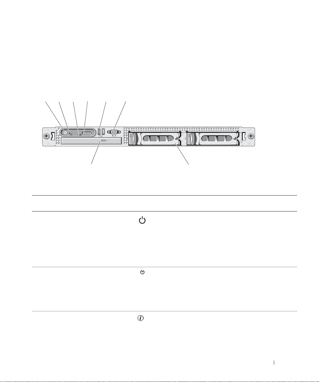
Front-Panel Features and Indicators
Figure 1 -1 shows the controls, indicators, and connectors located behind the optional rack bezel on the
system's front panel.
Figure 1-1. Front-Panel Features and Indicators
21
8
Table 1-2. Front-Panel LED Indicators, Buttons, and Connectors
Ite
m
1 Power-on indicator, power button The power button controls the DC power supply output to
Indicator, Button, or Connector Icon Description
6543
7
the system.
NOTE: If you turn off the system using the power button
and the system is running an ACPI-compliant operating
system, the system performs a graceful shutdown before
the power is turned off. If the system is not running an
ACPI-compliant operating system, the power is turned of f
immediately after the power button is pressed.
2 NMI button Used to troubleshoot software and device driver errors
when using certain operating systems. This button can be
pressed using the end of a paper clip.
Use this button only if directed to do so by qualified
support personnel or by the operating system's
documentation.
3 System identification button The identification buttons on the front and back panels can
be used to locate a particular system within a rack. When
one of these buttons is pushed, the blue system status
indicator on the front and back blinks until one of the
buttons is pushed again.
About Your System 11
Page 12
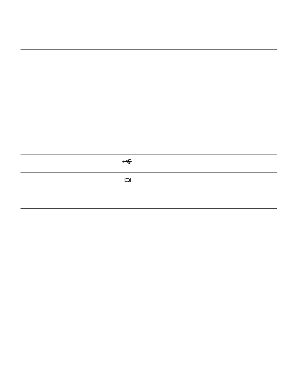
Table 1-2. Front-Panel LED Indicators, Buttons, and Connectors (continued)
Ite
m
4 LCD display Provides system ID, status information, and system error
Indicator, Button, or Connector Icon Description
messages.
The LCD display lights during normal system operation.
Both the systems management software and the
identification buttons located on the front and back of the
system can cause the LCD to flash blue to identify a
particular system.
The LCD display lights amber when the system needs
attention due to a problem with power supplies, fans,
system temperature, or hard drives.
NOTE: If the system is connected to AC power and an
error has been detected, the LCD display lights amber
regardless of whether the system has been powered on.
5 USB connectors (2) Connects USB 2.0-compliant devices to the system.
6 Video connector Connects a monitor to the system.
7 Hard drives (optional) Four 2.5" drives or two 3.5" drives (shown in figure).
8 Optical drive (optional) One optional slimline optical drive
NOTE: DVD devices are data only.
Hard-Drive Indicator Codes
If your hard drives are configured with the optional SAS RAID daughter card, two indicators on each of the
hard-drive carriers provide information on the status of the hard drives. See Figure 1-2 and Table 1-3. The
SAS backplane firmware controls the drive power-on/fault indicator.
12 About Your System
Page 13

Figure 1-2. Hard-Drive Indicators
1
2
1 drive-status indicator (green
and amber)
2 green drive-activity indicator
Table 1-3 lists the drive indicat or patterns. Different patterns are displayed as drive events occur in the
system. For example, if a hard-drive fails, the "drive failed" pattern appears. After the drive is selected for
removal, the "drive being prepared for removal" pattern appears, followed by the "drive ready for insertion
or removal" pattern. After the replacement drive is installed, the "drive being prepared for operation" pattern
appears, followed by the "drive online" pattern.
NOTE: For non-RAID configurations, only the drive-activity indicator is active. The drive-status indicator is off.
About Your System 13
Page 14
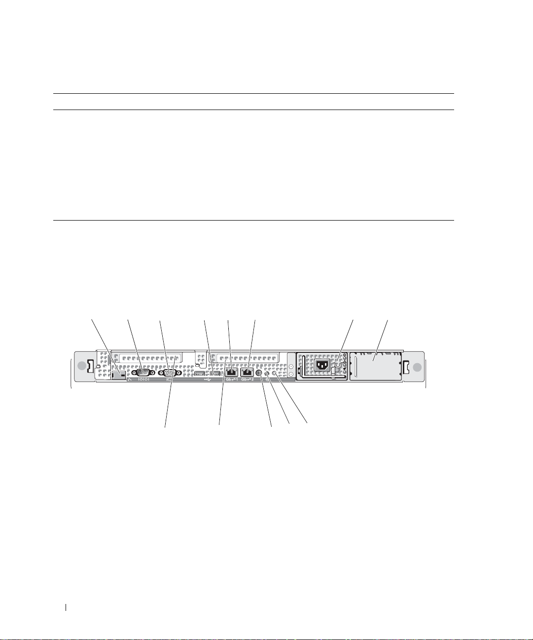
Table 1-3. Hard-Drive Indicator Patterns for RAID
Condition Drive-Status Indicator Pattern
Identify drive/preparing for removal Blinks green two times per second.
Drive ready for insertion or removal Off
Drive predicted failure Blinks green, amber, and off.
Drive failed Blinks amber four times per second.
Drive rebuilding Blinks green slowly.
Drive online Steady green.
Rebuild aborted Blinks green three seconds, amber three seconds, and off six seconds.
Back-Panel Features and Indicators
Figure 1-3 shows the controls, indicators, and connectors located on the system's back panel.
Figure 1-3. Back-Panel Features and Indicators
1 3
1 remote access controller
(optional)
4 USB connectors (2) 5 NIC1 connector 6 NIC2 connector
7 power supply 1 8 power supply 2 (optional) 9 system status indicator
10system identification button 11 system status indicator
13center PCI expansion slot
(slot 1)
2
13
4
5
12
2 serial connector 3 video connector
connector
6
9
10
11
7
12 left PCI expansion slot (slot 2)
8
14 About Your System
Page 15

Connecting External Devices
When connecting external devices to your system, follow these guidelines:
• Most dev ices must be connected to a specific connector and device drivers must be installed before the
device operates properly. (Device drivers are normally included with your operating system software or
with the device itself.) See the documentation that accompanied the device for specific installation and
configuration instructions.
• Alway s attach external devices while your system is turned off. Next, turn on any external devices before
turning on the system (unless the documentation for the device specifies oth erwise).
For information about individual connectors, se e "Jumpers and Connecto rs" on page 115. For information about
enabling, disabling, and configuring I/O ports and connectors, see "Using the System Setup Program" on
page 31.
Power Indicator Codes
The power button on the front panel controls the power input to the system's power supplies. The power
indicator can provide information on power status (see
codes.
Table 1-4. Power Button Indicators
Indicator Function
On Indicates that power is supplied to the system and the system is operational.
Off Indicates that no power is supplied to the system.
Figure 1-1
). Table 1-4 lists the power button indicator
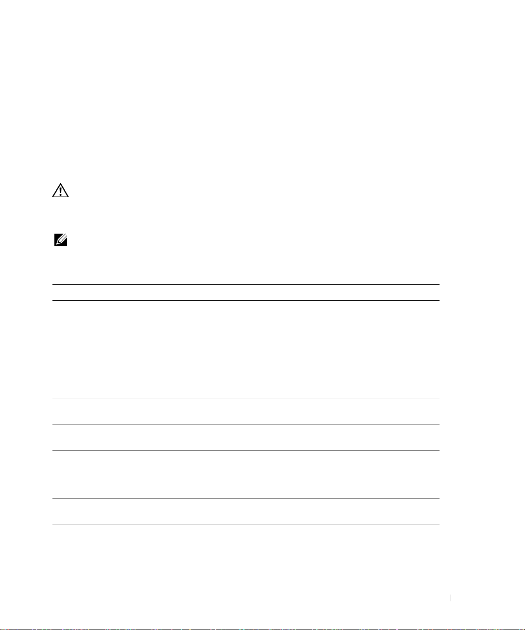
The indicators on the power supplies show whether power is present or whether a power fault has occurred
(see Figure 1-4).
Table 1-5. Power Supply Indicators
Indicator Function
Power supply status Green indicates that the power supply is operational.
Power supply fault Amber indicates a problem with the power supply.
AC line status Green indicates that a valid AC source is connected to the power supply.
About Your System 15
Page 16

Figure 1-4. Power Supply Indicators
1
2
3
1 power supply status indicator 2 power supply fault indicator 3 AC line status indicator
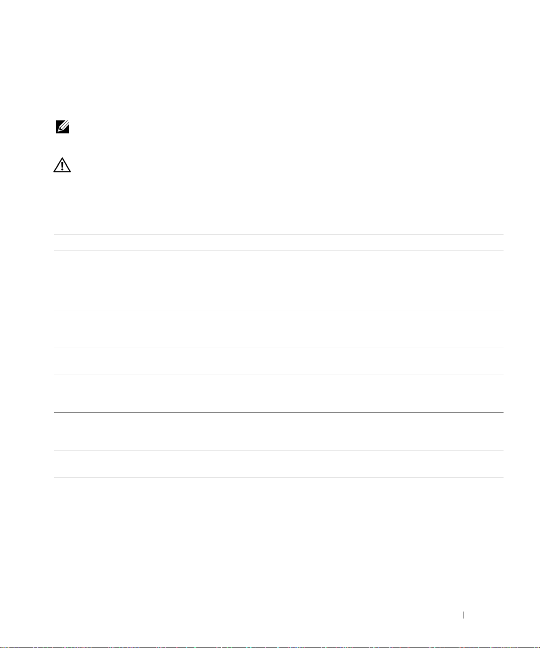
NIC Indicator Codes
Each NIC on the back panel has an indicator that provides information on network activity and link status.
See Figure 1-5. Table 1-6 lists the NIC indicator codes.
Figure 1-5. NIC Indicators
1
1 link indicator 2 activity indicator
Table 1-6. NIC Indicator Codes
Indicator Indicator Code
Link and activity indicators are off The NIC is not connected to the network.
Link indicator is green The NIC is connected to a valid link partner on the network.
Activity indicator is amber blinking Network data is being sent or received.
2
16 About Your System
Page 17
LCD Status Messages
The system's control panel LCD provides status messages to signify when the system is operating correctly
or when the system needs attention.
The LCD lights blue to indicate a normal operating condition, and lights amber to indicate an error
condition. The LCD scrolls a message that includes a status code followed by descriptive text. T able 1-7 lists
the LCD status messages that can occur and the probable cause for each message. The LCD messages refer
to events recorded in the System Event Log (SEL). For information on the SEL and configuring system
management settings, see the systems management software documentation.
CAUTION: Many repairs may only be done by a certified service technician. You should only perform
troubleshooting and simple repairs as authorized in your product documentation, or as directed by the online or
telephone service and support team. Damage due to servicing that is not authorized by Dell is not covered by your
warranty. Read and follow the safety instructions that came with the product.
NOTE: If your system fails to boot, press the System ID button for at least five seconds until an error code
appears on the LCD. Record the code, then see "Getting Help" on page 125.
Table 1-7. LCD Status Messages
Code Text Causes Corrective Actions
N/A SYSTEM NAME A 62-character string that can be
defined by the user in the System
Setup program.
The SYSTEM NAME displays
under the following conditions:
• The system is powered on.
• The power is off and active
POST errors are displayed.
E1000 FAILSAFE, Call
Support
E1114 Temp Ambient Ambient system temperature is out
of acceptable range.
E1116 Temp Memory Memory has exceeded acceptable
temperature and has been disabled
to prevent damage to the
components.
E12nn xx PwrGd Specified voltage regulator has
failed.
E1210 CMOS Batt CMOS battery is missing, or the
voltage is out of acceptable range.
This message is for information
only.
You can change the system string
in the System Setup program. See
"Using the System Setup Program"
on page 31.
See "Getting Help" on page 125.
See "Troubleshooting System
Cooling Problems" on page 101.
See "Troubleshooting System
Cooling Problems" on page 101.
See "Getting Help" on page 125.
See "Troubleshooting the System
Battery" on page 100.
About Your System 17
Page 18

Table 1-7. LCD Status Messages (continued)
Code Text Causes Corrective Actions
E1211 ROMB Batt RAID battery is either missing,
bad, or unable to recharge due to
thermal issues.
E1229 CPU # VCORE Processor # VCORE voltage
regulator has failed.
E1310 RPM Fan ## RPM of specified cooling fan is
out of acceptable operating range.
E1311 RPM Fan Mod #x RPM of fan x in the # module is
out of acceptable operating range.
E1313 Fan Redundancy The system is no longer fan-
redundant. Another fan failure will
put the system at risk of overheating.
E1410 CPU # IERR Specified microprocessor is
reporting an internal error.
E1414 CPU # Thermtrip Specified microprocessor is out of
acceptable temperature range and
has halted operation.
Reseat the RAID battery
connector. See "RAID Battery" on
page 60, and "Troubleshooting
System Cooling Problems" on
page 101.
See "Getting Help" on page 125.
See "Troubleshooting System
Cooling Problems" on page 101.
See "Troubleshooting System
Cooling Problems" on page 101.
Check control panel LCD for
additional scrolling messages. See
"Troubleshooting System Cooling
Problems" on page 101.
See your system’s "Information
Update T e ch Sheet" located on
support.dell.com for the most
current system information. If the
problem persists, see "Getting
Help" on page 125.
See "Troubleshooting System
Cooling Problems" on page 101. If
the problem persists, ensure that
the microprocessor heat sinks are
properly installed. See
"Troubleshooting the
Microprocessors" on page 108.
NOTE: The LCD continues to
display this message until the
system’s power cord is
disconnected and reconnected to
the AC power source, or the SEL
is cleared using either Server
Assistant or the BMC
Management Utility. See the Dell
OpenManage Baseboard
Management Controller User’s
Guide for information about these
utilities.
18 About Your System
Page 19

Table 1-7. LCD Status Messages (continued)
Code Text Causes Corrective Actions
E1418 CPU # Presence Specified processor is missing or
bad, and the system is in an
unsupported configuration.
E141C CPU Mismatch Processors are in a configuration
unsupported by Dell.
E141F CPU Protocol The system BIOS has reported a
processor protocol error.
E1420 CPU Bus PERR The system BIOS has reported a
processor bus parity error.
E1421 CPU Init The system BIOS has reported a
processor initialization error.
E1422 CPU Machine Chk The system BIOS has reported a
machine check error .
E1610 PS # Missing No power is available from the
specified power supply; specified
power supply is improperly
installed or faulty.
E1614 PS # Status No power is available from the
specified power supply; specified
power supply is improperly
installed or faulty.
E1618 PS # Predictive Power supply voltage is out of
acceptable range; specified power
supply is improperly installed or
faulty.
E161C PS # Input Lost Power source for specified power
supply is unavailable, or out of
acceptable range.
E1620 PS # Input Range Power source for specified power
supply is unavailable, or out of
acceptable range.
See "Troubleshooting the
Microprocessors" on page 108.
See "System Memory" on page 63.
Ensure that your processors match
and conform to the type described
in the Microprocessor Technical
Specifications outlined in your
system’s Getting Started Guide.
See "Getting Help" on page 125.
See "Getting Help" on page 125.
See "Getting Help" on page 125.
See "Getting Help" on page 125.
See "Troubleshooting Power
Supplies" on page 100.
See "Troubleshooting Power
Supplies" on page 100.
See "Troubleshooting Power
Supplies" on page 100.
Check the AC power source for the
specified power supply. If the
problem persists, see
"Troubleshooting Power Supplies"
on page 100.
Check the AC power source for the
specified power supply. If the
problem persists, see
"Troubleshooting Power Supplies"
on page 100.
About Your System 19
Page 20

Table 1-7. LCD Status Messages (continued)
Code Text Causes Corrective Actions
E1624 PS Redundancy The power supply subsystem is no
longer redundant. If the last supply
fails, the system will go down.
E1710 I/O Channel Chk The system BIOS has reported an
I/O channel check.
E1711 PCI PERR B## D##
F##
PCI PERR Slot #
E1712 PCI SERR B## D##
F##
PCI SERR Slot #
E1714 Unknown Err The system BIOS has determined
E171F PCIE Fatal Err
B## D## F##
PCIE Fatal Err
Slot #
The system BIOS has reported a
PCI parity error on a component
that resides in PCI configuration
space at bus ##, device ##,
function ##.
The system BIOS has reported a
PCI parity error on a component
that resides in the specified PCI
slot.
The system BIOS has reported a
PCI system error on a component
that resides in PCI configuration
space at bus ##, device ##,
function ##.
The system BIOS has reported a
PCI system error on a component
that resides in the specified slot.
that there has been an error in the
system, but is unable to determine
its origin.
The system BIOS has reported a
PCIe fatal error on a component
that resides in PCI configuration
space at bus ##, device ##,
function ##.
The system BIOS has reported a
PCIe fatal error on a component
that resides in the specified slot.
See "Troubleshooting Power
Supplies" on page 100.
See "Getting Help" on page 125.
Remove and reseat the PCI
expansion cards. If the problem
persists, see "Troubleshooting
Expansion Cards" on page 107.
If the problem persists, the riser
card or system board is faulty. See
"Getting Help" on page 125.
Remove and reseat the PCI
expansion cards. If the problem
persists, see "Getting Help" on
page 125.
If the problem persists, the riser
card or system board is faulty. See
"Getting Help" on page 125.
See "Getting Help" on page 125.
Remove and reseat the PCI
expansion cards. If the problem
persists, see "Troubleshooting
Expansion Cards" on page 107.
If the problem persists, the riser
card or system board is faulty. See
"Getting Help" on page 125.
E1810 HDD ## Fault The SAS subsystem has
determined that hard drive ## has
experienced a fault.
20 About Your System
See "Troubleshooting a Hard
Drive" on page 104.
Page 21

Table 1-7. LCD Status Messages (continued)
Code Text Causes Corrective Actions
E1811 HDD ## Rbld Abrt The specified hard drive has
experienced a rebuild abort.
E1812 HDD ## Removed The specified hard drive has been
removed from the system.
E1913 CPU & Firmware
Mismatch
E1A14 SAS Cable A SAS cable A is missing or bad. Reseat the cable. If the problem
E1A15 SAS Cable B SAS cable B is missing or bad. Reseat the cable. If the problem
E1A17 Pwr Cable FB Flex bay power cable is missing or
E1A18 PDB Ctrl Cable Flex bay control signals cable is
E2010 No Memory No memory is installed in the
E2011 Mem Config Err Memory detected, but is not
E2012 Unusable Memory Memory is configured, but not
E2013 Shadow BIOS Fail The system BIOS failed to copy its
E2014 CMOS Fail CMOS failure. CMOS RAM not
E2015 DMA Controller DMA controller failure. See "Getting Help" on page 125.
The BMC firmware does not
support the CPU.
bad.
missing or bad.
system.
configurable. Error detected
during memory configuration.
usable. Memory subsystem failure.
flash image into memory.
functioning properly.
See "Troubleshooting a Hard
Drive" on page 104. If the problem
persists, see your RAID
documentation.
Information only.
Update to the latest BMC
firmware. See the BMC User’s
Guide for more information on
setup and use of BMC.
persists, replace the cable. See
"SAS Controller Daughter Card"
on page 56.
persists, replace the cable. See
"SAS Controller Daughter Card"
on page 56.
Reseat the cable. If the problem
persists, replace the cable. See
"SAS Controller Daughter Card"
on page 56.
Reseat the cable. If the problem
persists, replace the cable. See
"SAS Controller Daughter Card"
on page 56.
Install memory. See "Installing
Memory Modules" on page 65.
See "Troubleshooting System
Memory" on page 102.
See "Troubleshooting System
Memory" on page 102.
See "Troubleshooting System
Memory" on page 102.
See "Getting Help" on page 125.
About Your System 21
Page 22

Table 1-7. LCD Status Messages (continued)
Code Text Causes Corrective Actions
E2016 Int Controller Interrupt controller failure. See "Getting Help" on page 125.
E2017 Timer Fail Timer refresh failure. See "Getting Help" on page 125.
E2018 Prog Timer Programmable interval timer error. See "Getting Help" on page 125.
E2019 Parity Error Parity error. See "Getting Help" on page 125.
E201A SIO Err SIO failure. See "Getting Help" on page 125.
E201B Kybd Controller Keyboard controller failure. See "Getting Help" on page 125.
E201C SMI Init System management interrupt
(SMI) initialization failure.
E201D Shutdown Test BIOS shutdown test failure. See "Getting Help" on page 125.
E201E POST Mem Test BIOS POST memory test failure. See "Troubleshooting System
E201F DRAC Config Dell remote access controller
(DRAC) configuration failure.
E2020 CPU Config CPU configuration failure. Check for specific error messages.
E2021 Memory
Population
E2022 POST Fail General failure after video. Check for specific error messages.
E2110 MBE Crd # DIMM ##
& ##
Incorrect memory configuration.
Memory population order
incorrect.
One of the DIMMs in the set
implicated by "## & ##" has had a
memory multi-bit error (MBE). If
no memory card is present, the
"Crd #" string is left out of the
message.
See "Getting Help" on page 125.
Memory" on page 102. If the
problem persists, see "Getting
Help" on page 125.
Check for specific error messages.
Ensure that DRAC cables and
connectors are properly seated. If
the problem persists, see your
DRAC documentation.
Check for specific error messages.
See "Troubleshooting System
Memory" on page 102.
See "Troubleshooting System
Memory" on page 102.
22 About Your System
Page 23

Table 1-7. LCD Status Messages (continued)
Code Text Causes Corrective Actions
E2111 SBE Log Disable
Crd # DIMM ##
E2112 Mem Spare Crd #
DIMM ##
E2113 Mem Mirror Crd #
DIMM ## & ##
E2118 Fatal NB Mem CRC One of the connections in the FBD
E2119 Fatal SB Mem CRC One of the connections in the FBD
I1910 Intrusion System cover has been removed. Information only.
I1911 >3 ERRs Chk Log LCD overflow message.
The system BIOS has disabled
memory single-bit error (SBE)
logging, and will not resume
logging further SBEs until the
system is rebooted. "##" represents
the DIMM implicated by the
BIOS. If no memory riser card is
present, the "Crd #" string is left
out of the message.
The system BIOS has spared the
memory because it has determined
that the memory had too many
errors. "## & ##" represents the
DIMM pair implicated by the
BIOS. If no memory card is
present, the "Crd #" string is left
out of the message.
The system BIOS has disabled
memory mirroring because it has
determined that one half of the
mirror has had too many errors.
"## & ##" represents the DIMM
pair implicated by the BIOS. If no
memory card is present, the "Crd
#" string is left out of the message.
memory subsystem link on the
Northbound side has failed.
memory subsystem link on the
Southbound side has failed.
A maximum of three error
messages can display sequentially
on the LCD. The fourth message
displays as the standard overflow
message.
See "Troubleshooting System
Memory" on page 102.
See "Troubleshooting System
Memory" on page 102.
See "Troubleshooting System
Memory" on page 102.
See "Troubleshooting System
Memory" on page 102.
See "Troubleshooting System
Memory" on page 102.
Check the SEL for details on the
events.
About Your System 23
Page 24

Table 1-7. LCD Status Messages (continued)
Code Text Causes Corrective Actions
I1912 SEL Full System Event Log is full of events,
and is unable to log any more
events.
W1228 ROMB Batt < 24hr Warns pre dictively that the RAID
battery has less than 24 hours of
charge left.
Clear the log by deleting event
entries.
Replace RAID battery. See "RAID
Battery" on page 60.
NOTE: For the full name of an abbreviation or acronym used in this table, see the "Glossary" on page 147.
Solving Problems Described by LCD Status Messages
The code and text on the LCD can often specify a very precise fault condition that is easily corrected. For
example, if the code E1418 CPU_1_Presence appears, you know that a microprocessor is not
installed in socket 1.
In contrast, you might be able to determine the problem if multiple related errors occur . For example, if you
receive a series of messages indicating multiple voltage faults, you might determine that the problem is a
failing power supply.
Removing LCD Status Messages
For faults associated with sensors, such as temperature, voltage, fans, and so on, the LCD message is
automatically removed when that sensor returns to a normal state. For example, if temperature for a
component goes out of range, the LCD displays the fault; when the temperature returns to the acceptable
range, the message is removed from the LCD. For other faults, you must take action to remove the message
from the display:
• Clear the SEL — You can perform this task remotely, but you will lose the event history for the system.
• Power cycle — Turn of f the system and disconnect it from the electrical outlet; wait approximately ten
seconds, reconnect the power cable, and restart the system.
Any of these actions will remove fault messages, and return the status indicators and LCD colors to the
normal state. Messages will reappear under the following conditions:
• The sensor returns to a normal state but fails again, resulting in a new SEL entry.
• The system is reset and new error events are detected.
• A failure is recorded from another source that maps to the same display entry.
24 About Your System
Page 25
System Messages
System messages appear on the screen to notify you of a possible problem with the system. Table 1-8 lists
the system messages that can occur and the probable cause and corrective action for each message.
NOTE: If you receive a system message that is not listed in Table 1-8, check the documentation for the
application that is running when the message appears or the operating system's documentation for an explanation
of the message and recommended action.
CAUTION: Many repairs may only be done by a certified service technician. You should only perform
troubleshooting and simple repairs as authorized in your product documentation, or as directed by the online or
telephone service and support team. Damage due to servicing that is not authorized by Dell is not covered by your
warranty. Read and follow the safety instructions that came with the product.
Table 1-8. System Messages
Message Causes Corrective Actions
Alert! Redundant memory
disabled! Memory
configuration does not
support redundant memory.
Attempting to update
Remote Configuration.
Please wait...
BIOS Update Attempt
Failed!
Caution! NVRAM_CLR jumper
is installed on system
board.
CPUs with different cache
sizes detected!
Decreasing available
memory
DIMM pairs must be matched
in size, speed, and
technology. The following
DIMM pair is mismatched:
DIMM x and DIMM y.
Installed memory modules are not the
same type and size; faulty memory
module(s).
Remote Configuration request has been
detected and is being processed.
Remote BIOS update attempt failed. Retry the BIOS update. If the problem
NVRAM_CLR jumper is installed.
CMOS has been cleared.
Microprocessors with different cache
sizes are installed.
Faulty or improperly installed memory
modules.
Mismatched or unmatched DIMMs
installed; faulty or improperly seated
memory module(s).
Ensure that all memory modules are of the
same type and size and that they are
properly installed. If the problem persists,
see "Troubleshooting System Memory"
on page 102.
Wait until the process is complete.
persists, see "Getting Help" on page 125.
Remove NVRAM_CLR jumper. See
Figure 6-1 for jumper location.
Ensure that all microprocessors have the
same cache size and that they are properly
installed. See "Processors" on page 67.
See "Troubleshooting System Memory"
on page 102.
Ensure that all pairs of memory modules
are of the same type and size and that th ey
are properly installed. See "System
Memory" on page 63. If the problem
persists, see "Troubleshooting System
Memory" on page 102.
About Your System 25
Page 26

Table 1-8. System Messages (continued)
Message Causes Corrective Actions
DIMMs must be populated in
sequential order beginning
with slot 1. The following
DIMM is electrically
isolated: DIMM x.
DIMMs should be installed
in pairs. Pairs must be
matched in size, speed,
and technology.
Dual-rank DIMM paired with
Single-rank DIMM - The
following DIMM/rank has
been disabled by BIOS:
DIMM x Rank y
Error: Incorrect memory
configuration. DIMMs must
be installed in pairs of
matched memory size,
speed, and technology.
Error: Memory failure
detected. Memory size
reduced. Replace the
faulty DIMM as soon as
possible.
!!*** Error: Remote Access
Controller initialization
failure*** RAC virtual USB
devices may not be
available...
FBD training error: The
following branch has been
disabled: Branch x
Gate A20 failure Faulty keyboard controller; faulty
The specified DIMM is inaccessible to
the system due to its location. DIMMs
must be populated in sequential order,
beginning with slot 1.
Mismatched or unmatched DIMMs
installed; faulty or improperly seated
memory module(s). The system will
operate in a degraded mode with
reduced ECC protection. Only memory
installed in channel 0 will be
accessible.
Mismatched DIMMs installed; faulty
memory module(s). The system has
detected a dual-rank DIMM paired with
a single-rank DIMM. The second rank
of the dual-rank DIMM will be
disabled.
Mismatched or unmatched DIMMs
installed; faulty or improperly seated
memory module(s).
Faulty or improperly seated memory
module(s).
Remote Access Controller initialization
failure.
The specified branch (channel pair)
contains DIMMs that are incompatible
with each other .
system board.
Populate 2, 4, 8, or 12 DIMMs
sequentially beginning with slot 1. See
"System Memory" on page 63.
Ensure that all pairs of memory modules
are of the same type and size and that th ey
are properly installed. See "System
Memory" on page 63. If the problem
persists, see "Troubleshooting System
Memory" on page 102.
Ensure that all pairs of memory modules
are of the same type and size and that th ey
are properly installed. See "System
Memory" on page 63. If the problem
persists, see "Troubleshooting System
Memory" on page 102.
Ensure that all pairs of memory modules
are of the same type and size and that th ey
are properly installed. See "System
Memory" on page 63. If the problem
persists, see "Troubleshooting System
Memory" on page 102.
See "Troubleshooting System Memory"
on page 102.
Ensure that the Remote Access Controller
is properly installed. See "RAC Card" on
page 71.
Ensure that only Dell-qualified memory is
used. Dell recommends purchasing
memory upgrade kits directly from
www.dell.com or your Dell sales agent to
ensure compatibility.
See "Getting Help" on page 125.
26 About Your System
Page 27

Table 1-8. System Messages (continued)
Message Causes Corrective Actions
General failure The operating system is unable to carry
out the command.
Invalid NVRAM
configuration, Resource
Re-allocated
Keyboard Controller
failure
Manufacturing mode
detected
MEMBIST failure - The
following DIMM/rank has
been disabled by BIOS:
DIMM x Rank y
Memory address line
failure at address, read
value expecting value
Memory double word logic
failure at address, read
value expecting value
Memory odd/even logic
failure at address, read
value expecting value
Memory write/read failure
at address, read value
expecting value
Memory tests terminated by
keystroke.
No boot device available Faulty or missing optical drive
System detected and corrected a
resource conflict.
Faulty keyboard controller; faulty
system board
System is in manufacturing mode. Reboot to take the system out of
Faulty memory module(s). See "Troubleshooting System Memory"
Faulty or improperly installed memory
modules.
POST memory test terminated by
pressing the spacebar.
subsystem, hard drive, or hard-drive
subsystem, or no boot disk in drive A.
This message is usually followed by
specific information. Note the
information, and take the appropriate
action to resolve the problem.
No action is required.
See "Getting Help" on page 125.
manufacturing mode.
on page 102.
See "Troubleshooting System Memory"
on page 102.
Information only.
Use a CD or hard drive. If the problem
persists, see "Troubleshooting an Optical
Drive" on page 103 and "Troubleshooting
a Hard Drive" on page 104. See "Using
the System Setup Program" on page 31
for information on setting the order of
boot devices.
About Your System 27
Page 28

Table 1-8. System Messages (continued)
Message Causes Corrective Actions
No boot sector on hard
drive
No timer tick interrupt Faulty system board. See “"Getting Help" on page 125."
Northbound merge error -
The following DIMM has
been disabled by BIOS:
DIMM x
Incorrect configuration settings in
System Setup program, or no operating
system on hard drive.
The specified DIMM was unable to
establish a successful data link with the
memory controller.
Check the hard-drive configuration
settings in the System Setup program. See
"Using the System Setup Program" on
page 31. If necessary, install the operating
system on your hard drive. See your
operating system documentation.
See "Troubleshooting System Memory"
on page 102.
PCIe Degraded Link Width
Error: Embedded
Bus#nn/Dev#nn/Funcn
Expected Link Width is n
Actual Link Width is n
PCIe Degraded Link Width
Error: Slot n
Expected Link Width is n
Actual Link Width is n
PCIe Training Error:
Embedded
Bus#nn/Dev#nn/Funcn
PCIe Training Error:
Slot n
PCI BIOS failed to install PCI device BIOS (Option ROM)
Plug & Play Configuration
Error
Faulty or improperly installed PCIe
card in the specified slot.
Faulty or improperly installed PCIe
card in the specified slot.
Faulty or improperly installed PCIe
card in the specified slot.
checksum failure is detected during
shadowing.
Loose cables to expansion card(s);
faulty or improperly installed
expansion card(s).
Error encountered in initializing PCI
device; faulty system board.
Reseat the PCIe card in the specified slot
number. See "Expansion-Card Riser" on
page 82. If the problem persists, see
"Getting Help" on page 125.
Reseat the PCIe card in the specified slot
number. See "Expansion-Card Riser" on
page 82. If the problem persists, see
"Getting Help" on page 125.
Reseat the PCIe card in the specified slot
number. See "Expansion-Card Riser" on
page 82. If the problem persists, see
"Getting Help" on page 125.
Reseat the expansion card(s). Ensure that
all appropriate cables are securely
connected to the expansion card(s). If the
problem persists, see "Troubleshooting
Expansion Cards" on page 107.
Install the NVRAM_CLR jumper and
reboot the system. See Figure 6-1 for
jumper location. If the problem persists,
see "Troubleshooting Expansion Cards"
on page 107.
28 About Your System
Page 29

Table 1-8. System Messages (continued)
Message Causes Corrective Actions
Read fault
Requested sector not found
Remote configuration
update attempt failed
ROM bad checksum = address Expansion card improperly installed or
Sector not found
Seek error
Seek operation failed
Shutdown failure Shutdown test failure. See "Troubleshooting System Memory"
The amount of system
memory has changed
Time-of-day clock stopped Faulty battery or faulty chip. See "Troubleshooting the System Battery"
The following DIMM pair is
not compatible with the
memory controller: DIMM x
and DIMM y
The following DIMMs are
not compatible: DIMM x and
DIMM y
The operating system cannot read from
the diskette or hard drive, the system
could not find a particular sector on the
disk, or the requested sector is
defective.
System unable to process Remote
Configuration request.
faulty.
Faulty diskette or hard drive. See "Troubleshooting a Hard Drive" on
Memory has been added or removed or
a memory module may be faulty.
The specified DIMM(s) are
incompatible with the system.
The specified DIMM(s) are
incompatible with the system.
Replace the diskette. Ensure that the
diskette and hard drive cables are properly
connected. See "Troubleshooting
Expansion Cards" on page 107, or
"Troubleshooting a Hard Drive" on
page 104 for the appropriate drive(s)
installed in your system.
Retry Remote Configuration.
Reseat the expansion card(s). Ensure that
all appropriate cables are securely
connected to the expansion card(s). If the
problem persists, see "Troubleshooting
Expansion Cards" on page 107.
page 104 for the appropriate drive(s)
installed in your system.
on page 102.
If memory has been added or removed,
this message is informative and can be
ignored. If memory has not been added or
removed, check the SEL to determine if
single-bit or multi-bit errors were detected
and replace the faulty memory module.
See "Troubleshooting System Memory"
on page 102.
on page 100.
Ensure that only Dell-qualified memory is
used. Dell recommends purchasing
memory upgrade kits directly from
www.dell.com or your Dell sales agent to
ensure compatibility.
Ensure that only ECC FBD1 memory is
used. Dell recommends purchasing
memory upgrade kits directly from
www.dell.com or your Dell sales agent to
ensure compatibility.
About Your System 29
Page 30

Table 1-8. System Messages (continued)
Message Causes Corrective Actions
Time-of-day not set please run SETUP program
Timer chip counter 2
failed
Unsupported CPU
combination
Unsupported CPU stepping
detected
Utility partition not
available
Incorrect Time or Date settings; faulty
system battery.
Faulty system board. See "Getting Help" on page 125.
Microprocessor(s) is not supported by
the system.
The <F10> key was pressed during
POST, but no utility partition exists on
the boot hard drive.
Check the Time and Date settings. See
"Using the System Setup Program" on
page 31. If the problem persists, replace
the system battery. See "Syste m Ba ttery"
on page 86.
Install a supported microprocessor or
microprocessor combination. See
"Processors" on page 67.
Create a utility partition on the boot hard
drive. See the CDs that came with your
system.
Warning Messages
A warning message alerts you to a possible problem and prompts you to respond before the system
continues a task. For example, before you format a diskette, a message will warn you that you may lose all
data on the diskette. Warning messages usually interrupt the task and require you to respond by typing
(yes) or
n (no).
y
NOTE: W arning messages are generated by either the applica tion or the operating system. For more information,
see the documentation that accompanied the operating system or application.
Diagnostics Messages
When you run system diagnostics, an error message may result. Diagnostic error messages are not covered
in this section. Record the message on a copy of the Diagnostics Checklist in "Getting Help" on page 125,
and then follow the instructions in that section for obtaining technical assistance.
Alert Messages
Systems management software generates alert messages for your system. Al ert m essages include
information, status, warning, and failure messages for drive, temperature, fan, and power conditions. For
more information, see the systems management software documentation.
30 About Your System
Page 31

2
Using the System Setup Program
After you set up your system, run the System Setup program to familiarize yourself with your system
configuration and optional settings. Record the information for future reference.
You can use the System Setup program to:
• Change the system configuration stored in NVRAM after you add, change, or remove hardware
• Set or change user-selectable options—for example, the time or date
• Enable or disable integrated devices
• Correct discrepancies between the installed hardware and configuration settings
Entering the System Setup Program
1
Turn on or restart your system.
2
Press <F2> immediately after you see the following message:
<F2> = System Setup
If your operating system begins to load before you press <F2>, allow the system to finish boot ing,
and then restart your system and try again.
NOTE: To ensure an orderly system shutdown, see the documentation that accompanied your
operating system.
Responding to Error Messages
You can enter the System Setup program by respondi ng to certain error messages. If an error message
appears while the system is booting, make a note of the message. Before entering the System Setup
program, see "System Messages" on page 25 for an explanation of the message and suggestions for
correcting errors.
NOTE: After installing a memory upgrade, it is normal for your system to send a message the first time you
start your system.
Using the System Setup Program
Table 2-1 lists the keys that you use to view or chang e information on the System Setup program
screens and to exit the program.
Using the System Setup Program 31
Page 32

Table 2-1. System Setup Program Navigation Keys
Keys Action
Up arrow or <Shift><Tab> Moves to the previous field.
Down arrow or <Tab> Moves to the next field.
Spacebar, <+> , <
arrows
<Esc> Exits the System Setup program and restarts the system
<F1> Displays the System Setup program's help file.
NOTE: For most of the options, any changes that you make are recorded but do not take effect until you restart
the system.
–>, left and right
Cycles through the settings in a field. In many fields,
you can also type the appropriate value.
if any changes were made.
System Setup Options
Main Screen
When you enter the System Setup program, the main System Setup pr ogram screen appears (see Figure 2-1).
32 Using the System Setup Program
Page 33

Figure 2-1. Main System Setup Program Screen
Table 2-2 lists the options and descrip tio ns for the inform atio n fields that appear on the main System Setup
program screen. For related information, see "System Security Screen Options" on page 37.
NOTE: The options for the System Setup program change based on the system configuration.
NOTE: The System Setup program defaults are listed under their respective options, where applicable.
Ta ble 2-2. System Setup Program Options
Option Description
System Time Resets the time on the system's internal clock.
System Date Resets the date on the system's internal calendar.
Memory Information Displays information related to installed system, video, and redundant memory,
including size, type, and speed of memory modules, system memory test option
status, and redundant memory status.
CPU Information Displays information related to microprocessors (speed, cache size, and so on). See
"CPU Information Screen" on page 35."
SATA Port x Displays type and capacity of drive attached to port x.
Using the System Setup Program 33
Page 34

Ta ble 2-2. System Setup Program Options (continued)
Option Description
Boot Sequence Determines the order in which the system searches for boot devices during system
startup. A vailable options can include the diskette drive, CD drive, hard drives, and
network. If you have installed a RAC, additional options, such as virtual floppy and
virtual CD-ROM, may be present.
NOTE: System boot is not supported from an external device attached to a SAS or
SCSI adapter. See support.dell.com for the latest support information about booting
from external devices.
USB Flash Drive T ype
Auto
default)
(
Integrated Devices See "Integrated Devices Screen" on page 36.
PCI IRQ Assignment Displays a screen to change the IRQ assigned to each of the integrated devices on the
Serial Communication
(Off default)
Failsafe Baud Rate
(57600 default)
Remote Terminal Type
(VT 100/VT 220 default)
Redirection After Boot
(Enabled default)
Embedded Server
Management
System Security Displays a screen to configure the system password and setup password features. See
Keyboard NumLock
(
On
default)
Report Keyboard Errors
(
Report
default)
Determines the emulation type for a USB flash drive. Hard disk allows the USB flash
drive to act as a hard drive. Floppy allows the USB flash drive to act as a removal
diskette drive. Auto automatically chooses an emulation type.
PCI bus, and any installed expansion cards that require an IRQ.
Options are On with Console Redirection via COM2, and Off.
Displays the failsafe baud rate used for console redirection when the baud rate cannot
be negotiated automatically with the remote terminal. This rate should not be
adjusted.
Select either VT 100/VT 220 or ANSI.
Enables or disables BIOS console redirection after your system boots to the operating
system.
Displays a screen to configure the front-panel LCD options and to set a user-defined
LCD string. For more information, see the systems management software
documentation that describes the features, requirements, installation, and basic
operation of the embedded software.
"System Security Screen" on page 37, "Using the System Password" on page 38, and
"Using the Setup Password" on page 40 for more information.
Determines whether your system starts up with the NumLock mode activated on 101or 102-key keyboards (does not apply to 84-key keyboards).
Enables or disables reporting of keyboard errors during the POST. Select Report for
host systems that have keyboards attached. Select Do Not Report to suppress all error
messages relating to the keyboard or keyboard controller during POST. This setting
does not affect the operation of the keyboard itself if a keyboard is attached to the
system.
34 Using the System Setup Program
Page 35

CPU Information Screen
Table 2-3 lists the options and descrip tio ns for the inform atio n fields that appear on the CPU Information
screen.
Table 2-3. CPU Information Screen
Option Description
Bus Speed Displays the bus speed of the processors.
Logical Processor
(Enabled default)
Virtualization Technology
(Disabled default)
Adjacent Cache Line
Prefetch
(Enabled default)
Hardware Prefetcher
(Enabled default)
Demand-Based Power
Management
(Disabled default)
Processor X ID Displays the family and model number of each processor. A submenu
Displays when the processors support HyperThreading. Enabled
permits all logical processors to be used by the operating system.
Only the first logical processor of each processor installed in the
system is used by the operating system if Disabled is selected.
Displays when the processor(s) support Virtualization Technology.
Enabled permits virtualization software to utilize Virtualization
Technology functions incorporated in the processor design. This
feature can only be used by software that supports Virtualization
Technology.
Enables or disables optimal use of sequential memory access. Disable
this option for applications that require high use of random memory
access.
Enables or disables the hardware prefetcher.
Enables or disables demand-based power management. When
enabled, the CPU Performance State tables will be reported to the
operating system; when disabled, the CPU Performance State tables
will not be reported to the operating system. If any of the CPUs do not
support demand-based power management, the field will become
read-only , and automatically set to Disabled.
displays processor and core speed, amount of level 2 cache, and the
number of cores.
Using the System Setup Program 35
Page 36

Integrated Devices Screen
T able 2-4 lists the options and descriptions for the information fields that appear on the Integrated Devices
screen.
Table 2-4. Integrated Devices Screen Options
Option Description
Integrated SAS Controller
(Enabled default)
Embedded SATA
Controller
(Off default)
IDE CD-ROM Controller
(Auto default)
User-Accessible USB Ports
(All Ports On default)
Embedded Gb NIC1
(Enabled with PXE
default)
MAC Address Displays the MAC address for NIC1. This field does not have user -selectable settings.
TOE Capability Displays the TCP/IP Offload Engine (TOE) feature status of NIC1.
Embedded Gb NIC2
(Enabled without PXE
default)
MAC Address Displays the MAC address for NIC2. This field does not have user -selectable settings.
TOE Capability Displays the TCP/IP Offload Engine (TOE) feature status of NIC2.
Enables or disables the integrated SAS controller.
Allows the integrated SATA controller to be set to Off or ATA mode.
Enables the integrated IDE controller. When set to
IDE controller is enabled if IDE devices are attached to the chann el and an ex ternal ID E
controller is not detected.
Auto
, each channel of the integrated
NOTE: This CD-ROM option will not appear on this menu screen if your system
does not include this optional device.
Enables or disables the system's user-accessible ports. Options are All Ports On,
Only Back Ports On, or All Ports Off. Disabling the USB ports makes system
resources available for other devices.
Enables or disables the system's integ rated NIC1. Options are Enabled without PXE,
Enabled with PXE, and Disabled. PXE support allows the system to boot from the
network. Changes take effect after the system reboots.
Enables or disables the system's integ rated NIC2. Options are Enabled without PXE,
Enabled with PXE, and Disabled. PXE support allows the system to boot from the
network. Changes take effect after the system reboots.
36 Using the System Setup Program
Page 37

System Security Screen
Table 2-5 lists the options and descrip tio ns for the inform atio n fields that appear on the System Security
screen.
Table 2-5. System Security Screen Options
Option Description
System Password Displays the current status of your system's password security feature and allows you
to assign and verify a new system password.
NOTE: See "Using the System Passwo rd" on page38 for instructions on assigning a
system password and using or changing an existing system password.
Setup Password Restricts access to the System Setup program in the same way that you restrict access
to your system using the system password feature.
NOTE: See "Using the Setup Password" on page 40 for instructions on assigning a
setup password and using or changing an existing setup password.
Password Status Setting the Setup Passw ord option to Enabled prevents the system password from
being changed or disabled at system start-up.
To loc k the system password, assign a setup password in the Setup Password option
and then change the Password Status option to Locked. In this state, you cannot
change the system password using the System Password option and cannot be
disabled at system start-up by pressing <Ctrl><Enter>.
To unlock the system password, enter the setup password in the Setup Password field
and then change the Password Status option to Unlocked. In this state, you can
disable the system password at system start-up by pressing <Ctrl><Enter> and then
change the password using the System Password option.
Power Button
NMI Button NOTICE: Use the NMI button only if directed to do so by qualified support
Turns system's power off and on.
• If you turn off the system using the power button and the system is ru nning an A C PIcompliant operating system, the sy stem can perform an orderly shutdown before
power is turned off.
• If the system is not running an ACPI-compliant operating system, power is turned off
immediately after the power button is pressed.
The button is enabled in the System Setup program. When disabled, the button can
only turn on system power.
NOTE: You can still turn on the system by using the power button, even if the Power
Button option is set to Disabled.
personnel or by the operating system's documentation. Pressing this button halts
the operating system and displays a diagnostic screen.
Enables or disables the NMI feature.
Using the System Setup Program 37
Page 38

Table 2-5. System Security Screen Options (continued)
Option Description
AC Power Recovery
(Last default)
Determines how the system reacts when power is restored to the system. If system is
set to Last, the system returns to the last power state. On turns on the system after
power is restored. When set to Off, the system remains off after power is restored.
Exit Screen
After you press <Esc> to exit the System Setup program, the Exit screen displays the following options:
•
Save Changes and Exit
• Discard Changes and Exit
• Return to Setup
System and Setup Password Features
NOTICE: The password features provide a basic level of security for the data on your system. If your data
requires more security, use additional forms of protection, such as data encryption programs.
NOTICE: Anyone can access the data stored on your system if you leave the system running and unattended
without having a system password assigned or if you leave your system unlocked so that someone can disable the
password by changing a jumper setting.
Your system is shipped to you without the system password feature enabled. If system security is a concern,
operate your system only with system password protection.
To chang e or delete an existing password, you must know the password (see "Deleting or Changing an
Existing System Password" on page 40). If you forget your password, you cannot operate your system or
change settings in the System Setup program until a trained service technician changes the password jumper
setting to disable the passwords, and erases the existing passwords. This procedure is described in
"Disabling a Forgotten Password" on page 117.
Using the System Password
After a system password is assigned, only those who know the password have full use of the system. When
the System Password option is set to Enabled, the system prompts you for the system password after the
system starts.
Assigning a System Password
Before you assign a system password, enter the System Setup program and check the System Password
option.
38 Using the System Setup Program
Page 39

When a system password is assigned, the setting shown for the System Password option is Enabled. If the
setting shown for the Password Status is Unlocked, you can change the system password. If the Password
Status option is Locked, you cannot change the system password. When the system password feature is
disabled by a jumper setting, the system password is Disabled, and you cannot change or enter a new system
password.
When a system password is not assigned and the password jumper on the system board is in the enabled
(default) position, the setting shown for the System Password option is Not Enabled and the Password
Status field is Unlocked. To assign a system password:
1
Verify that the
2
Highlight the
3
Type your new system password.
Password Status
System Password
option is set to
Unlocked
option and press <Enter>.
.
You can use up to 32 characters in your password.
As you press each character key (or the spacebar for a blank space), a plac eholder appears in the field.
The password assignment is not case-sensitiv e. Howeve r, certain key combinations are not valid. To erase
a character when entering your password, press <Backspace> or the left-arrow key.
NOTE: To escape from the field without assigning a system password, press <Enter> to move to another
field, or press <Esc> at any time prior to completing step 5.
4
Press <Enter>.
5
T o confirm your password, type it a second time and press <Enter>.
The setting shown for the
System Password
changes to
Enabled
. Exit the System Setup program and
begin using your system.
6
Either reboot your system now for your password protection to take effect or continue working.
NOTE: Password protection does not take effect until you reboot the system.
Using Your System Password to Secure Your System
NOTE: If you have assigned a setup password (see "Using the Setup Password" on page 40"), the system accepts
your setup password as an alternate system password.
When the Password Status option is set to Unlocked, you have the option to leave the password security
enabled or to disable the password security.
To leave the password security enabled:
1
Turn on or reboot your system by pressing <Ctrl><Alt><Del>.
2
Type your password and press <Enter>.
To disable the password security:
1
Turn on or reboot your system by pressing <Ctrl><Alt><Del>.
2
Type your password and press <Ctrl><Enter>.
Using the System Setup Program 39
Page 40

When the Password Status option is set to Locked whenever y ou turn on your system or reboot your
system by pressing <Ctrl><Alt><Del>, type your password and press <Enter> at the prompt.
After you type the correct system password and press <Enter>, your system operates as usual.
If an incorrect system password is entered, the system displays a message and prompts you to re-enter your
password. You have three attempts to enter the correct password. After the third unsuccessful attempt, the
system displays an error message showing the number of unsuccessful attempts and that the system has
halted and will shut down. This message can alert you to an unauthorized person attempting to use your
system.
Even after you shut down and restart the system, the error message continues to be displayed until the
correct password is entered.
NOTE: You can use the Password Status option in conjunction with the System Password and Setup Password
options to further protect your system from unauthorized changes.
Deleting or Changing an Existing System Password
1
When prompted, press <Ctrl><Enter> to disable the existing system password.
If you are asked to enter your setup password, contact your network administrator.
2
Enter the System Setup program by pressing <F2> during POST.
3
Select the
4
When prompted, type the system password.
5
Confirm that
If
Not Enabled
Enabled
System Security
Not Enabled
is displayed for the
is displayed for the
is displayed for the
screen field to verify that the
System Password
System Password
System Password
option, press the <Alt><b> key combination to restart the
Password Status
option is set to
Unlocked
.
option.
option, the system password has been deleted. If
system, and then repeat steps 2 through 5.
Using the Setup Password
Read the information in the following sections to assign or change your setup password.
Assigning a Setup Password
You can assign (or change) a setup password only when the Setup Password option is set to Not Enabled.
T o assign a setup password, highlight the Setup Password option and press the <+> or <–> key . The system
prompts you to enter and verify the password. If a character is illegal for password use, the system beeps.
NOTE: The setup password can be the same as the system password. If the two passwords are different, the setup
password can be used as an alternate system password. However, the system password cannot be used in place of
the setup password.
You can use up to 32 characters in your password.
As you press each character key (or the spacebar for a blank space), a placeholder appears in the field.
40 Using the System Setup Program
Page 41

The password assignment is not case-sensitive. However, certain key combinations are not valid. If you
enter one of these combinations, the system beeps. To erase a character when entering your password, press
<Backspace> or the left-arrow key.
After you verify the password, the Setup Password setting changes to Enabled. The next time you enter the
System Setup program, the system prompts you for the setup password.
A change to the Setup Password option becomes effective immediately (restarting the system is not
required).
Operating With a Setup Password Enabled
If Setup Password is set to Enabled, you mu st enter th e correct setup password before you can modify
most of the System Setup options. When you start the System Setup program, the program prompts you to
enter a password.
If you do not enter the correct password in three attempts, the system lets you view, but not modify, the
System Setup screens—with the following exception: If System Password is not set to Enabled and is not
locked through the Password Status option, you can assign a system password (however, you cannot
disable or change an existing system password).
NOTE: You can use the Password Status option in conjunction with the Setup Password option to protect the
system password from unauthorized changes.
Deleting or Changing an Existing Setup Password
1
Enter the System Setup program and select the
2
Highlight the
<Enter> twice to clear the existing setup password.
The setting changes to
Setup Password
Not Enabled
option, press <Enter> to access the setup password window, and press
.
System Security
option.
3
If you want to assign a new setup password, perform the steps in "Assigning a Setup Password" on
page 40.
Disabling a Forgotten Password
See "Disabling a Forgotten Password" on page 117.
Baseboard Management Controller Configuration
The Baseboard Management Controller (BMC) enables configuring, monitoring, and recovery of systems
remotely. BMC provides the following features:
• Uses the system’s integrated NIC
• Fault logging and SNMP alerting
• Access to system event log and sensor status
• Control of system functions including power on and off
Using the System Setup Program 41
Page 42

• Support is independent of the system’s power or operating state
• Provides text console redirection for system setup, text-based utilities, and operating system consoles
NOTE: To remotely access the BMC through the integrated NIC, you must connect the network connection to
integrated NIC1.
For additional information on using BMC, see the documentation for the BMC and systems management
applications.
Entering the BMC Setup Module
1
Turn on or restart your system.
2
Press <
Ctrl-E
If your operating system begins to load before you press <
and then restart your system and try again.
> when prompted after POST.
Crtl-E
>, allow the system to finish booting,
BMC Setup Module Options
For information about the BMC Setup Module options and how to configure the emergency management port
(EMP), see the
BMC User ’s Guide
.
42 Using the System Setup Program
Page 43

Installing System Components
This section describes how to install the following system components:
• Cooling fan modules
• Cooling shrouds
• Power supplies
• SAS controller daughter card or SAS RAID controller daughter card
• RAID battery
• RAID controller expansion card
• Expansion cards
• Boot drive
• System me mory
• Processors
• RAC card
• Optical drive
• Hard drives
• SAS backplane boards
•Risers
• Sideplane board
• System battery
• Control panel assembly
• System bo ard
3
Installing System Components 43
Page 44

Recommended Tools
You may need the following items to perform the procedures in this section:
• Key to the system keylock
• #2 Phillips screwdriver
• T10 Torx driver
• Small flat-blade screwdriver
• Wrist grounding strap
Inside the System
CAUTION: Many repairs may only be done by a certified service technician. You should only perform
troubleshooting and simple repairs as authorized in your product documentation, or as directed by the online or
telephone service and support team. Damage due to servicing that is not authorized by Dell is not covered by your
warranty. Read and follow the safety instructions that came with the product.
CAUTION: The memory modules can become extremely hot during normal operation. Allow the modules
sufficient time to cool before handling.
In Figure 3-1, the bezel, system cover, and memory cooling shroud are removed to provide an interior view
of the system.
Figure 3-1. Inside the System
3
4
2
1
14
13
44 Installing System Components
12
5
11
6
7
8
9
10
Page 45

1 control panel 2 SAS controller daughter card
or SAS RAID controller
daughter card (optional)
4 cooling fan modules (4) 5 power supply bays (2) 6 left riser (slot 2)
7 center riser (slot 1) 8 battery 9 system board cooling shroud
10memory modules (8) 11 heatsink/microprocessor (2) 12 backplane
3 sideplane
13two 3.5-inch or four 2.5-inch
hard drive bays
14 optical slimline drive
(optional)
The system board holds the system's control circuitry and other electronic components. Several hardware
options, such as the microprocessors and memory, are installed directly on the system board. The left and
center risers each have one slot and can accommodate up to two half-length PCI-X cards or two half-length
PCIe expansion cards. For more information, see "Expansion Cards" on page 61.
The system provides space for one optional slimline optical drive. The optical drive tray connects to the
controller on the system board through the sideplane board. For more information, see "Installing the Optical
Drive Tray" on page 74.
The hard-drive bays provide space for up to two 3.5-inch or four 2.5-inch SAS/SATA hard drives. The hard
drives connect to a SAS controller daughter card or a SAS RAID controller daughter card. For more
information, see "Installing a Hot-Plug Hard Drive" on page 76.
During an installation or troubleshooting procedure, you may be required to change a jumper setting. For
more information, see "Jumpers and Connectors" on page 115.
NOTE: There are no hot-pluggable components inside this system except for externally accessible components,
such as the power supplies and the hard drives.
Removing and Replacing the Front Bezel
1
The system is enclosed by an optional bezel. To upgrade or troubleshoot the system, remove the bezel and
cover to access the internal system components. Unless you are installing a hot-plug ha rd drive, turn off
the system and attached peripherals, and disconnect the system from the electrical outlet and peripherals.
NOTE: You do not need to remove the front bezel to remove the system cover.
2
Using the system key, unlock the bezel.
3
Press the tab at the left end of the bezel.
4
Rotate the left end of the bezel away from the system to release the right end of the bezel.
5
Pull the bezel away from the system. See Figure 3-2.
Installing System Components 45
Page 46

Figure 3-2. Removing the Bezel
1
2
1 key lock 2 bezel cover
To replace the front bezel, perform the preceding steps in reverse.
Opening and Closing the System
CAUTION: Many repairs may only be done by a certified service technician. You should only perform
troubleshooting and simple repairs as authorized in your product documentation, or as directed by the online or
telephone service and support team. Damage due to servicing that is not authorized by Dell is not covered by your
warranty. Read and follow the safety instructions that came with the product.
CAUTION: Whenever you need to lift the system, get others to assist you. To avoid injury, do not attempt to lift
the system by yourself.
CAUTION: The memory modules can become extremely hot during normal operation. Allow the modules
sufficient time to cool before handling.
Opening the System
To upgrade or troubleshoot the system, remove the system cover to gain access to internal components.
1
Turn off the system and attached peripherals, and disconnect the system from the electrical outlet and
peripherals.
2
Remove the bezel. See "Removing and Replacing the Front Bezel" on page 45.
3
To remove the system cover, rotate the latch release lock on the latch in a counter clockwise direction to
the unlocked position. See Figure 3-3.
46 Installing System Components
Page 47

4
Lift up on the latch on top of the system to guide it back and into an offset position. See Figure 3-3.
5
Grasp the cover on both sides and carefully lift the cover away from the system.
Figure 3-3. Removing the Cover
1
2
3
4
1 latch 2 latch release lock 3 alignment J hooks
4 chassis tabs
Closing the System
1
Lift up the latch on the cover.
2
Place the cover on top of the system and offset the cover slightly back so that it clears the chassis J hooks
and lays flat on the system chassis. See Figure 3-3.
3
Lower the cover into the closed position aligning it with the J hooks and push down on the latch to guide
the cover into place.
4
Rotate the latch release lock in a clockwise direction to secure the cover.
Installing System Components 47
Page 48

Cooling Fan Modules
This system contains four cooling fan modules, each comprised of two dual-rotor fans, for a total of eight fans
that are connected directly to the system board.
Removing a Cooling Fan Module
CAUTION: Many repairs may only be done by a certified service technician. You should only perform
troubleshooting and simple repairs as authorized in your product documentation, or as directed by the online or
telephone service and support team. Damage due to servicing that is not authorized by Dell is not covered by your
warranty. Read and follow the safety instructions that came with the product.
NOTE: The procedure for removing each individual fan module is the same.
1
Turn off the system and attached peripherals, and disconnect the system from the electrical outlet and
peripherals.
2
Open the system. See "Opening and Closing the System" on page 46.
NOTE: You can remove the fan modules without removing the memory cooling shroud; however, Dell
recommends that you remove this shroud before removing a fan module. Do not remove the system board cooling
See "Removing the Memory Cooling Shroud" on page 52.
shroud.
3
Raise the fan handle, disconnect the module wire harne ss from the system board, and pull the fan straight
up to clear the chassis. See Figure3-4.
4
Unplug the fan module connector.
48 Installing System Components
Page 49

Figure 3-4. Removing and Installing a Cooling Fan
2
1
1 cooling fan modules (4) 2 fan module handles 3 module wire harness
4 cooling fan module connector 5 system board cooling shroud
3
4
5
Replacing a Cooling Fan Module
NOTE: The procedure for installing each individual fan is the same.
1
Ensure that the fan handle is upright and lower the fan into its retention base until the fan is fully seate d.
Then lower the fan handle until it snaps into place. See Figure 3-4.
2
Attach the fan module connectors.
3
If you removed the memory cooling shroud to access the fan modules, replace the shroud. See "Replacing
the Memory Cooling Shroud" on page 53.
4
Close the system. See "Opening and Closing the System" on page 46.
Installing System Components 49
Page 50

Removing the Plastic Fan Guide
NOTE: The plastic fan guide is mounted to the chassis between the fans.
NOTE: You may need to remove the system from the rack.
1
Remove the cooling fan modules. See "Removing a Cooling Fan Module" on page 48.
2
Remove the system from the rack. See the Rack Installation Guide for your system.
3
Place the system upside-down on a flat surface.
4
Using a #2 Phillips screwdriver , remove the two screws from the botto m of the chassis th at secure the fan
bracket.
5
Turn the system right-side up, place it on a flat surface, and then remove the fan bracket.
Replacing the Plastic Fan Guide
1
While the system is out of the rack, and with the top cover removed, place the system on its side on a flat
surface.
2
Place the fan bracket into its location inside the chassis.
3
Holding the fan bracket in place, use a #2 Phillips screwdriver to replace the two screws on the bottom of
the chassis.
4
Place the system right-side up on a flat surface.
5
Replace the cooling fan modules. See "Replacing a Cooling Fan Module" on page 49.
6
Replace the system in the rack. See the Rack Installation Guide for your system.
Cooling Shrouds
Your system contains two cooling shrouds.
• System board cooling shroud
• Memory cooling shroud
System Board Cooling Shroud
The
system board cooling shroud directs airflow over the system memory modules, chan neling the air from the
four fan modules. See Figure 3-5.
50 Installing System Components
Page 51

Figure 3-5. System Board Cooling Shroud
1
1 system board cooling shroud
Removing the System Board Cooling Shroud
1
If applicable, remove the bezel. See "Removing and Replacing the Front Bezel" on page 45.
2
Turn off the system and attached peripherals, and then disconnect the syst em fro m the electrical outlet.
3
Open the system. See "Opening the System" on page 46.
4
Remove the memory cooling shroud. See "Removing the Memory Cooling Shroud" on page 52.
5
Remove both the center and left risers from the system board. See "Removing an Expansion-Card Riser"
on page 82.
6
Press the tabs on the front side of the shroud (nearest to the processors), and then lift the shroud up and
away from the system.
Installing the System Board Cooling Shroud
1
Align the back of the shroud to the front of the posts of the center and rear card risers on the motherboard.
2
Press down gently on the front of the shroud until it engages with the plastic tabs on the motherboa rd.
3
Place the center and left risers. See "Installing an Expansion-Card Riser" on page 83.
4
Replace the memory cooling shroud. See "Replacing the Memory Co oling Shroud" on page 53.
5
Close the system. See "Closing the System" on page 47.
Installing System Components 51
Page 52

6
If applicable, replace the bezel. See "Removing and Replacing the Front Bezel" on page 45.
7
Attach any peripherals, connect the system to the electrical source, and then turn on the system.
Memory Cooling Shroud
The memory cooling shroud covers both the memory mod ules (DIMMs) and t he processors. This shroud c an be
removed and installed. See Figure 3-6 and "System Board Removal" on page 91.
Removing the Memory Cooling Shroud
CAUTION: Many repairs may only be done by a certified service technician. You should only perform
troubleshooting and simple repairs as authorized in your product documentation, or as directed by the online or
telephone service and support team. Damage due to servicing that is not authorized by Dell is not covered by your
warranty. Read and follow the safety instructions that came with the product.
CAUTION: The memory modules are hot to the touch for some time after the system has been powered down.
Allow time for the memory modules to cool before handling them. Handle the memory modules by the card edges
and avoid touching the components on the memory module.
NOTICE: Never operate your system with the memory cooling shroud removed. Overheating of the system can
develop quickly resulting in a shutdown of the system and the loss of data.
1
To remove the cooling shroud, locate the release tab on the shroud edge that is nearest to the adjacent
system board shroud. See Figure 3-6.
2
Pull up on the release tab to release the memory cooling shroud.
3
Unseat the shroud from the securing tabs located on the periphery of the shrou d.
4
Carefully lift the shroud straight up to disengage it from the system board, and then lift the shroud away
from the system.
52 Installing System Components
Page 53

Figure 3-6. Memory Cooling Shroud
1
1 memory cooling shroud 2 memory shroud release tab 3 memory modules (8)
4 system processors (2)
Replacing the Memory Cooling Shroud
1
To install the memory cooling shroud, align the shroud directly over the memory modules and the
2
3
4
processors.
2
Using the interior system board cooling shroud as a guide, slowly lower the shroud straight down on to the
system, directly over the processors and memory modules.
3
Gently press around the periphery of the shroud until it engages with the external tabs and snaps into
place.
Power Supplies
Your system supports one or two power supplies rated at an output of 670 W. If only one power supply is
installed, it must be installed in the left power supply bay (bay 1). If two power supplies are installed, the
second power supply serves as a redundant, hot-plug power source.
NOTICE: In a non-redundant configuration, the power supply blank must be installed in the unoccupied power
supply bay to ensure proper system cooling. See "Installing the Power Supply Blank" on page 56.
Installing System Components 53
Page 54

Removing a Power Supply
NOTICE: The system requires one power supply for the system to operate normally. The system is in the
redundant mode when two power supplies are installed and both power supplies are connected to an AC power
source. Remove and replace only one power supply at a time in a system that is powered on. Operating the system
with only one power supply installed and without a power supply blank installed for extended periods of time can
cause the system to overheat.
NOTICE: If only one power supply is installed, it must be installed in the left power supply bay (1).
NOTICE: If you connect the system to a power source in the range of 120 to 220 VAC, and if two power supplies
are installed, the second power supply serves as a redundant, hot-plug power source.
NOTE: On your rack system, you may have to unlatch and lift the cable management arm if it interferes with
power supply removal. For information about the cable management arm, see the system’s Rack Installation
Guide.
1
If your system has a single power supply, turn off the system and all attached peripherals. For a redundant
system, you can leave the system running and proceed to the next step.
2
Disconnect the power cable from the power source.
3
Disconnect the power cable from the power supply and remove the ca ble from the ca ble re tention brac ket.
NOTICE: On a rack system, you may need to temporarily unlatch and lift the cable management arm. For
information about the cable management arm, see the system’s Rack Installation Guide.
4
Release the locking tab on the left side of the power supply by pressing in toward the right until the power
supply is released from the chassis. See Figure 3-7.
5
Holding the power-supply handle, pull the power sup ply stra ight out to clear the chassis.
54 Installing System Components
Page 55

Figure 3-7. Removing and Installing a Power Supply
1
1 power-supply 2 power-supply handle 3 cable retention bracket
4 power supply blank 5 power-supply bay 2 (optional) 6 redundant power supply bay 1
7 locking tab
2
3
7
4
5
6
Replacing a Power Supply
1
If you are adding a second power supply, remove the power supply blank. See "Removing a Power
Supply" on page 54.
2
Holding the power-supply handle, slide the new power supply into the chassis until it is fully seated and
contacts the system chassis. See Figure 3-7.
NOTICE: On a rack system, you may need to temporarily unlatch and lift the cable management arm. For
information about the cable management arm, see the system’s Rack Installation Guide.
3
Insert the power cable through the cable retention bracket, connect the power cab le to the power supply,
and plug the cable into a power outlet.
NOTICE: For more information about the power cable retention bracket, see the Getting Started With Your
System guide.
NOTE: After installing a new power supply in a system with two power supplies, allow several seconds for the
system to recognize the power supply and determine its status. The power-supply status indicator turns green to
signify that the power supply is functioning properly (see Figure 1-4).
Installing System Components 55
Page 56

Removing the Power Supply Blank
Press the latch on the left side to release and remove the blank, rotating the blank slightly to clear the bay,
and remove from the chassis.
NOTICE: To ensure proper system cooling, the power supply blank must be installed on the unoccupied power
supply bay in a non-redundant configuration. Remove the power supply blank only if you are installing a second
power supply.
Installing the Power Supply Blank
To inst all the power supply blank, insert the tab on the right edge of the blank into the slot in the power
supply bay wall. Rotate the blank into the power supply bay until it is fully seated.
SAS Controller Daughter Card
Your system includes a dedicated slot on the sideplane for an optional SAS controller daughter card. The
SAS controller daughter card provides the SAS storage subsystem for your system’s two optional internal
hard drives. The optional SAS RAID controller daughter card allows you to set up any internal hard drives
in a RAID configuration.
Removing a SAS Controller Daughter Card
1
If you are removing a SAS RAID controller daughter card, disconnect the battery cable from the card by
releasing the tab on the cable connector on the daughter card. See Figure 3-26.
2
Pull on the release latch on the daughter card (see Figure 3-8) and slide the daughter card tray towards the
hard drives.
3
Continue to hold the guide rails outward as you pull the SAS controller daughter card upw ard from the
rails.
Installing a SAS Controller Daughter Card or SAS RAID Controller Daughter Card
NOTICE: If you are installing a SAS RAID daughter card, be careful not to press on the memory module on the
card (see Figure ). to avoid damaging the memory module or its socket.
NOTICE: If you are installing a new or replacement SAS RAID daughter card, do not remove the card’s plastic
cover until you have completed installing the card.
1
Hold the metal daughter card tray by its edges with the release latch and edge connector facing the
sideplane board. See Figure 3-8.
2
Align the two slots in the daughter card tray and the corresponding tabs on the chassis, then low er the card
tray onto the chassis.
3
Slide the daughter card tray towards the sideplane until the edge connecto r on the dau ghter card fits into
the socket on the sideplane board and the release latch engages. See Figure 3-8.
56 Installing System Components
Page 57

Figure 3-8. Installing a SAS Controller Daughter Card
4
3
2
1
5
6
7
8
1 SAS controller daughter card
and tray assembly
4 release latch 5 RAID battery connector (SAS
7 SAS RAID connector 0 (to
backplane SAS A)
4
Attach any cables from the internal storage daughter card to the backplan e, referring to Figure 3-9 and
2 sideplane 3 daughter card socket
6 RAID memory module
RAID controller daughter card
only)
8 alignment slots in card tray (2)
(DIMM) (SAS RAID
controller daughter card only)
Figure 3-10 for the cabling guidelines for your system’s card and backplane conf iguration.
NOTICE: You must follow the cabling diagrams for connecting the hard drives to either of the internal storage
daughter cards that are illustrated in the following figures to ensure proper connection. Figure 3-9 illustrates the
cable routing for the SAS controller daughter card and Figure 3-10 illustrates the cable routing for the SAS RAID
controller daughter card.
Installing System Components 57
Page 58

Figure 3-9. Cable Routing for the SAS Controller Daughter Card
3
2
1
1 SAS connector SAS 0 2 SAS controller daughter card 3 SAS backplane connector
SAS A
58 Installing System Components
Page 59

Figure 3-10. Cable Routing for the SAS RAID Controller Daughter Card
3
2
1
1 SAS RAID connector SAS 0 2 SAS RAID controller
daughter card
3 SAS backplane connector
SAS A
Installing System Components 59
Page 60

RAID Battery
Installing a RAID Battery
1
Locate the RAID battery pocket on the chassis that is adjacent to hard drive bay 0. See Figure 3-11.
2
Insert the battery in the battery pocket.
3
Connect the battery cable to the RAID controller daughter card. See Figure 3-11.
Figure 3-11. Installing a SAS RAID Battery
2
1
3
1 RAID battery 2 SAS RAID daughter card
battery connector
Removing a RAID Battery
1
Disconnect the RAID battery cable from the SAS RAID daughter card. See Figure 3-11.
2
Press the release latch toward the hard-drive bays and remove the battery from the battery pocket.
60 Installing System Components
3 release latch
Page 61

Expansion Cards
The system is available with one of two optional PCI riser configurations.
PCIe Riser Board Expansion Slots
The PCIe riser configuration provides two PCI Express expansion slots with the following features:
• Two PCIe risers, installed in the left and center riser connectors.
• Two x8-lane PCIe expans ion slots.
• Support for full height/half-length PCI cards in both slots.
PCI-X Riser Board Expansion Slots
The PCI-X riser configuration provides two PCI-X slots with the following features:
• Two PCI-X risers, installed in the le ft and center riser connectors.
• Two PCI-X 64-bit/133-M Hz expansion slots (on separate buses).
• Support for full height/half-length PCI cards in both slots.
Expansion Card Installation Guidelines
NOTE: You cannot combine PCIe and PCI-X risers. Two risers must be installed or the system will not power up.
NOTE: The expansion-card slots are not hot-pluggable.
To identify expansion slots, see Figure 3-12. The two expansion card slots are on separate buses.
Installing an Expansion Card
CAUTION: Many repairs may only be done by a certified service technician. You should only perform
troubleshooting and simple repairs as authorized in your product documentation, or as directed by the online or
telephone service and support team. Damage due to servicing that is not authorized by Dell is not covered by your
warranty. Read and follow the safety instructions that came with the product.
1
Unpack the expansion card and prepare it for installation.
For instructions, see the documentation accompanying the card.
2
Turn off the sys tem, including any attached peripherals, and disconnect the system from the electrical
outlet.
3
Open the system. See "Opening and Closing the System" on page 46.
4
If you are adding a new card, open the expansion-card latch and remove the filler bracket. See
Figure 3-12.
5
Install the expansion card:
a
Position the expansion card so that the card-edge con nector a ligns with the expansio n-ca rd conne ctor
on the PCI riser board.
Installing System Components 61
Page 62

b
Insert the card-edge connector firmly into the expansion-card connect or until the card is fully seated.
c
When the card is seated in the connector, close the expansion-card latch. See Figure 3-12.
Figure 3-12. Installing an Expansion Card
3
2
1
5
4
1 PCI riser 2 expansion-card connector 3 expansion-card latch
4 expansion card 5 card-edge connector
6
Connect any cables to the expansion card.
See the documentation that came with the card for information about its cable conne ctions.
7
Close the system. See "Opening and Closing the System" on page 46.
Removing an Expansion Card
CAUTION: Many repairs may only be done by a certified service technician. You should only perform
troubleshooting and simple repairs as authorized in your product documentation, or as directed by the online or
telephone service and support team. Damage due to servicing that is not authorized by Dell is not covered by your
warranty. Read and follow the safety instructions that came with the product.
1
Turn off the sys tem, including any attached peripherals, and disconnect the system from the electrical
outlet.
2
Open the system. See "Opening and Closing the System" on page 46.
3
Disconnect all cabl es from the card.
62 Installing System Components
Page 63

4
Remove the expansion card:
a
Open the expansion-card latch. See Figure 3-12.
b
Grasp the expansion card by its edges, and carefully remove it from the expansion-card connector.
5
If you are removing the card permanently, install a metal filler bracket over the empty expansion slot
opening and close the expansion-card latch.
NOTE: You must install a filler bracket over an empty expansion slot to maintain Federal Communications
Commission (FCC) certification of the system. The brackets also keep dust and dirt out of the system and aid
in proper cooling and airflow inside the system.
6
Close the system. See "Opening and Closing the System" on page 46.
Configuring the Boot Device
If you plan to boot the system from a hard drive, the drive must be attached to the primary (or boot)
controller. The device that the system boots from is determined by the boot order specified in the System
Setup program.
The System Setup program provides options that the system uses to scan for installed boot devices. See
"Using the System Setup Program" on page 31 for information about the System Setup program.
Configuring the Boot Drive
The drive or device from which the system boots is determined by the boot ord er specifie d in the System Se tup
program.
program
See "Using the System Setup Program" on page 31 for information about the System Setup
.
System Memory
You can upgrade your system memory to a maximum of 32 GB by installing 533-MHz or 667-MHz fully
buffered (FB) DDR II memory modules (DIMMs) in sets of 256-MB, 512-MB, 1-GB, 2-GB, or 4-GB modules.
The eight memory sockets are located on the system board under the memory coolin g shroud.You can purchase
memory upgrade kits from Dell.
NOTICE: If you remove your original memory modules from the system during a memory upgrade, keep them
separate from any new memory modules that you may have, even if you purchased the new memory modules from
Dell. Use only 533-MHz or 667-MHz DDR II fully buffered DIMMS (FBDs).
The memory module sockets are divided into two equal branches (0 and 1). Each branch consists of two
channels:
• Channel 0 and channel 1 are in branch 0.
• Channel 2 and channel 3 are in branch 1.
Installing System Components 63
Page 64

Each channel consists of two memory module sockets:
• Channel 0 contains DIMM_1, DIMM_5.
• Channel 1 contains DIMM _2, DIMM_6.
• Channel 2 contains DIMM_3, DIMM_7.
• Channel 3 contains DIMM _4, DIMM _8.
The first DIMM socket of each channel has white release tabs.
General Memory Module Installation Guidelines
To ensure optimal performance of your system, observe the following guidelines when configuring your
system memory.
• Use only qualified FBDs. FBDs can be either s
single
-r
anked and modules marked with a 2R are dual-ranked.
• A minimum of two identical FBDs must be installed.
• DIMM sockets must be populated by lowest number first.
• Memory modules m
total number of memory modules in the configuration must total two, four, or eight. For best system
performance, all four, or eight memory modules should be identical in size, speed, and technology.
•Memory sp
identical memory size, speed, and technology.
• Memory sparing and memory mirroring cannot be implemented at the same time.
aring and
ust be installed in pairs of matched memory size, speed, and technology
memory m
irroring require eight memory, and all memory modules must be of
ingle-ranked
or d
ual-ranked
. FBDs m
arked with a 1R are
, and the
Non-Optimal Memory Configurations
System performance can be affected if your memory configuration does not conform to the preceding
installation guidelines. Your system may issue an error message duri ng startup stating that your memory
configuration is non-optimal.
Memory Sparing Support
The system supports memory sparing if eight identical memory modules are insta lled in the system. The
memory sparing feature must be enabled in the System Setup program and can be used only if memory
mirroring is not enabled.(See "Using the System Setup Program" on page 31.)
Memory sparing allocates four ranks of DIMM memory to the spare bank. These four ranks consist of the
first rank of memory in DIMM sockets 1 through 4. For single-rank DIMMs, the entire capacity of the four
DIMMs is allocated to sparing whereas for dual-rank DIMMs, only half of the four-DIMM capacity is
allocated to sparing. Table 3-1 shows how memory sparing splits the available and spared memory in each
of the single- and dual-ranked memory module combinations.
64 Installing System Components
Page 65

Table 3-1. Memory Sparing Configurations
DIMMs Size/Type Total Memory Available Spare
8 256-MB single-rank 2 GB 1 GB 1 GB
512-MB single-rank 4 GB 2 GB 2 GB
1-GB single-rank 8 GB 4 GB 4 GB
2-GB single-rank 16 GB 8 GB 8 GB
2-GB dual-rank 16 GB 12 GB 4 GB
4-GB dual-rank 32 GB 24 GB 8 GB
Memory Mirroring Support
The system supports memory mirroring if eight identical memory modules are installed in the system.
Mirroring must be enabled in the System Setup program a nd can be used only if me mory sparing is not enab led.
(See "Using the System Setup Program" on page 31.) In a mirrored configuration, the total available system
memory is one-half of the total installed memory.
Installing Memory Modules
CAUTION: Many repairs may only be done by a certified service technician. You should only perform
troubleshooting and simple repairs as authorized in your product documentation, or as directed by the online or
telephone service and support team. Damage due to servicing that is not authorized by Dell is not covered by your
warranty. Read and follow the safety instructions that came with the product.
CAUTION: The memory modules are hot to the touch for some time after the system has been powered down.
Allow time for the memory modules to cool before handling them. Handle the memory modules by the card edges
and avoid touching the components on the memory module.
1
Open the system. See "Opening and Closing the System" on page 46.
2
Remove the memory cooling shroud. See "Removing the Memory Cooling Shroud" on page 52.
3
Locate the memory module sockets. See Figure 6-2.
4
Press the ejectors on the memory module socket down and out, as shown in Figure 3-13, to allow the
memory module to be inserted into the socket.
5
Handle each memory module only on either card edge, ensuring not to touch the middle of the memory
module.
Installing System Components 65
Page 66

Figure 3-13. Installing and Removing a Memory Module
1
2
3
1 memory module 2 memory module socket
ejectors (2)
6
Align the memory module's edge connector with the alignment key of the memory mo dule socket, and
3 alignment key
insert the memory module in the socket.
NOTE: The memory module socket has an alignment key that allows you to install the memory module in
the socket in only one way.
7
Press down on the memory module with your thumbs while pulling up on the ejectors with you r index
fingers to lock the memory module into the socket.
When the memory module is properly seated in the socket, the ejectors on the memory module socket
align with the ejectors on the other sockets that have memory modules installed.
8
Repeat step 3 through step 7 of this procedure to install the remaining memory modules. See Table 3-1.
9
Replace the memory cooling shroud. See "Replacing the Memory Co oling Shroud" on page 53.
10
Close the system. See "Opening and Closing the System" on page 46.
11
Press <F2> to enter the System Setup program, and check the
System Setup
screen.
System Memory
setting on the main
The system should have already changed the value to reflect the newly installed memory.
12
If the value is incorrect, one or more of the m emory modules may not be installed properly. Repeat ste p 1
through step 11 of this procedure, checking to ensure that the memory modules are firmly seated in their
sockets.
13
Run the system memory test in the system diagnostics. See "Running the System Diagnostics" on
page 111.
66 Installing System Components
Page 67

Removing Memory Modules
CAUTION: Many repairs may only be done by a certified service technician. You should only perform
troubleshooting and simple repairs as authorized in your product documentation, or as directed by the online or
telephone service and support team. Damage due to servicing that is not authorized by Dell is not covered by your
warranty. Read and follow the safety instructions that came with the product.
CAUTION: The memory modules are hot to the touch for some time after the system has been powered down.
Allow time for the memory modules to cool before handling them. Handle the memory modules by the card edges
and avoid touching the components on the memory module.
1
Open the system. See "Opening and Closing the System" on page 46.
2
Remove the memory cooling shroud. See "Removing the Memory Cooling Shroud" on page 52.
3
Locate the memory module sockets. See Figure 6-2.
4
Press down and out on the ejectors on each end of the socket until the memory module pops out of the
socket. See Figure 3-13.
Handle each memory module only on either card edge, ensuring not to touch the middle of the memory
module.
5
Replace the memory cooling shroud. See "Replacing the Memory Co oling Shroud" on page 53.
6
Close the system. See "Opening and Closing the System" on page 46.
Activating the Integrated NIC TOE
T o add TCP/IP Offload Engine (T OE) or iSCSI T OE functionality to the system's integrated NIC, install the
appropriate TOE or iSCSI TOE NIC hardware key in the TOE_KEY socket on the system board. S
Figure 6-2.
ee
Processors
You can upgrade your processor(s) to take advantage of future options in speed and functionality. Each
processor and its associated internal cache memory are contained in a land grid array (LGA) package that is
installed in a ZIF socket on the system board.
The following items are included in the processor upgrade kit:
• Processor
• Heat sink
Removing the Processor
CAUTION: Many repairs may only be done by a certified service technician. You should only perform
troubleshooting and simple repairs as authorized in your product documentation, or as directed by the online or
telephone service and support team. Damage due to servicing that is not authorized by Dell is not covered by your
warranty. Read and follow the safety instructions that came with the product.
1
Prior to upgrading your system, download the latest system BIOS version on
Installing System Components 67
support.dell.com
.
Page 68

2
Turn off the sys tem, including any attached peripherals, and disconnect the system from the electrical
outlet.
3
Open the system. See "Opening and Closing the System" on page 46.
4
Remove the memory cooling shroud. See "Removing the Memory Cooling Shroud" on page 52.
NOTICE: When you remove the heat sink, the possibility exists that the processor might adhere to the heat sink
and be removed from the socket. It is recommended that you remove the heat sink while the processor is warm.
NOTICE: Never remove the heat sink from a processor unless you intend to remove the pr ocessor. The heat sink
is necessary to maintain proper thermal conditions.
NOTICE: The processor and heat sink can become extremely hot. Be sure the processor has had sufficient time
to cool before handling.
5
Press the blue tab on the end of one of the heat-sink retention levers to disengage the lever, then lift the
lever 90 degrees. See Figure 3-14.
Figure 3-14. Installing and Removing the Heat Sink
1
2
3
1 heat sink 2 heat-sink retention lever (2) 3 retention lever latch
68 Installing System Components
Page 69

6
Wait 30 seconds for the heat sink to loosen from the processor.
7
Open the other heat sink retention lever.
8
If the heat sink has not separated from the processor, carefully rotate the heat sink in a clockwise, then
counterclockwise, direction until it releases from the processor. Do not pry the heat sink from the
processor.
9
Lift the heat sink off of the processor and set the heat sink upside down so as not to contaminate the
thermal grease.
10
Pull the socket-release lever 90 degrees upward until the processor is rele ased from the socket. See
Figure 3-15.
11
Rotate the processor shield upward and out of the way.
Figure 3-15. Installing and Removing the Processor
3
2
1
1 socket key (2) 2 notch in processor 3 processor shield
4 processor 5 socket-release lever 6 ZIF socket
12
Lift the processor shield to release the processor, and then lift the processor out of the socket. Leave the
4
6
5
release lever up so that the socket is ready for the new processor.
NOTICE: Be careful not to bend any of the pins on the LGA socket when removing the processor. Bending the
pins can permanently damage the socket and system board.
Installing System Components 69
Page 70

Installing a Processor
1
Unpack the new processor.
2 Align the processor with the
3Install the processor in the socket.
NOTICE: Positioning the processor incorrectly can permanently damage the system board or the processor when
you turn the system on.
a If the release lever on the processor socket is not positioned all the way up, move it to that position.
b With th e
NOTICE: Do not use force to seat the processor. When the processor is positioned correctly, it engages easily
into the socket.
c
W
p
rocessor and
hen the processor is fully seated in the socket, rotate the socket release lever back down until it
snaps into place, securing the processor.
d
Close the processor shield. See Figure 3-15.
4
Install the heat sink.
NOTE: If you did not receive a replacement heat sink, use the heat sink that you removed in step 9.
a
If you receive a heat sink and pre-applied thermal grease with your processor kit, remo ve the
protective sheet from the thermal grease layer on top of the heat sink.
If you did not receive a replacement heat sink with your processor kit, do the following :
• Using a clean lint-free cloth, remove the existing thermal grease from the he at sink you re mov ed
in step 9.
• Open the grease packet included with your processor kit and apply th erma l grease evenly to the
top of the processor.
b Place the heat sink onto the processor. See
c Close one of the two heat sink retention levers until it locks. See
d
Repeat for the other heat sink retention lever.
5
Close the system. See "Closing the System" on page 47.
As the system boots, it detects the presence of the new processor and automatically changes the system
configuration information in the System Setup program.
socket keys on t
the
socket
keys
he ZIF socket
. See Figure 3-15.
aligned, set the processor lightly in the socket.
See Figure 3-15.
Figure 3-14
.
Figure 3-14
.
6
Press <F2> to enter the System Setup program, and check that the processor information matches the new
system configuration.
See "Using the System Setup Program" on pa ge 31 for instructions about using the S ystem Setup progr am.
7
Run the system diagnostics to verify that the new processor operates correctly.
See "Running the System Diagnostics" on page 111 for information about running the diagnostics.
70 Installing System Components
Page 71

RAC Card
CAUTION: Many repairs may only be done by a certified service technician. You should only perform
troubleshooting and simple repairs as authorized in your product documentation, or as directed by the online or
telephone service and support team. Damage due to servicing that is not authorized by Dell is not covered by your
warranty. Read and follow the safety instructions that came with the product.
The optional Remote Access Controller (RAC) provides a set of advanced features for managing the server
remotely. The following procedure describes the steps for installing or removing the optional RAC card.
Installing a RAC Card
1
Turn of f the system, including any attach ed peripherals, an d then disconnec t the system from th e electrical
outlet.
2
Open the system. See "Opening the System" on page 46
3
If applicable, remove the plastic filler plug from the system back panel. See Figure 3-16.
4
Remove any PCI cards attached to the center riser. See "Removing an Expansion Card" on page 62.
5
Remove the center riser card from the system board. See "Expansion-Card Riser" on page 82.
6
Angle the RAC card so that its NIC conne ctor inserts through the back-p anel RA C card op ening , alig ning
the card with the back standoff.
Figure 3-16. Installing and Removing a RAC Card
2
1
3
6
4
5
1 RAC card 2 RAC-card connectors (2) 3 filler plug location
4 back standoff 5 front standoffs (2) 6 RAC-card cable connectors
Installing System Components 71
Page 72

7
Align the front edge of the RAC card with the front plastic retention standof fs, and then press down on the
front of the card until it is fully seated. See Figure 3-16.
When the front of the card is fully seated, the front plastic standoffs snap over the front edge of the card.
8
Connect the two small cables (44-pin cable and 50-pin cable), ensurin g that connector labeled "Planar" is
attached to the appropriate system board connector and the connecto r labeled "DRAC" is attached to the
appropriate RAC card connector.
9
Replace the center riser card. See "Expansion-Card Riser" on page 82.
10
Replace any PCI cards that were removed from the center riser. See "Installing an Expansion Card" on
page 61.
11
Close the system. See "Closing the System" on page 47.
12
Reconnect the system and peripherals to their power sources, and then turn them on.
See the RAC card documentation for information on configuring and using the RAC card.
Removing the RAC Card and Cables
1
Turn of f the system, including any attach ed peripherals, an d then disconnec t the system from th e electrical
outlet.
2
Open the system. See "Opening the System" on page 46.
3
Remove any PCI cards attached to the center riser. See "Removing an Expansion Card" on page 62.
4
Remove the center riser card from the system board. See "Expansion-Card Riser" on page 82.
5
Remove the RAC card cables from the system board connectors by pressing the met al tabs inward and
then pulling up.
6
Remove the RAC card cables from the RAC connectors by pressing the metal tabs inw ard and then
pulling up.
7
Remove the RAC card by pressing outwa rdly on th e front sta ndoffs, and then lifting the RAC card up and
out of the system.
8
Replace the center riser card. See "Expansion-Card Riser" on page 82.
9
Replace any PCI cards that were removed from the center riser. See "Installing an Expansion Card" on
page 61.
10
Close the system. See "Closing the System" on page 47.
11
Reconnect the system and peripherals to their power sources, and then turn them on.
72 Installing System Components
Page 73

Optical Drive
The optional slimline optical drive is mounted on a tray that slides into the front panel and connects to the
controllers on the system board through the sideplane board.
NOTE: DVD devices are data only.
Removing the Optical Drive Tray
CAUTION: Many repairs may only be done by a certified service technician. You should only perform
troubleshooting and simple repairs as authorized in your product documentation, or as directed by the online or
telephone service and support team. Damage due to servicing that is not authorized by Dell is not covered by your
warranty. Read and follow the safety instructions that came with the product.
1
Turn off the sys tem, including any attach ed peripherals, and the n disconnect the syste m from its electr ical
outlet.
2
Remove the bezel. See "Removing and Replacing the Front Bezel" on page 45.
3
Open the system. See "Opening and Closing the System" on page 46.
4
Remove the SAS controller daughter card. See "Removing a SAS Controller Daughter Card" on page 56.
5
Disconnect the optical-drive cable from the back of the drive. See Figure 3-17.
6
T o rem ove the optic al driv e, press forwa rd on the blue tray rel ease tab, and the n slide the driv e tray out of
the system. See Figure 3-17.
Installing System Components 73
Page 74

Figure 3-17. Removing and Installing the Optical Drive Tray
1
1 optical -drive tray 2 optical-drive cable 3 optical-drive release tab
4 optical drive
2
3
4
Installing the Optical Drive Tray
1
Align the optical drive tray with its opening in the front panel.
The optical drive opening is located directly below the SAS daughter card bay.
2
Slide in the drive tray until the tray snaps into place. See Figure 3-17.
3
Connect the optical-drive cable from the back of the drive. See Figure 3-17.
4
Replace the SAS controller daughter card.See "Installing a SAS Controlle r Daughter Card or SAS RAID
Controller Daughter Card" on page 56.
5
Close the system. See "Opening and Closing the System" on page 46.
6
Replace the bezel. See "Removing and Replacing the Front Bezel" on page 45.
7
Reconnect your system and peripherals to their electrical outlets, and turn on the system.
74 Installing System Components
Page 75

Hard Drives
This subsection describes how to install and configure SAS or SATA hard drives in the system's internal
hard-drive bays.
2.5-inch (SAS only) internal hard-drive bays that accommodate up to either two or fou r hard drives. All drives
connect to the system board through one of two optional backplane boards.
NOTE: Depending on the hard drive configuration you ordered, your hard drive(s) may come with a drive
interposer that allows your SATA drive to attach to the SAS connector on the backplane.
Before You Begin
Hard drives are supplied in special hot-pluggable drive carriers that fit in the hard-drive bays. Depending on
your configuration, you received one of the following two drive carrier types:
• SATA drive carrier — Usable only with a SATA hard drive.
• SATAu drive carrier — Usable with either a SAS hard drive or a SATA hard drive with a universal
interposer card. The interposer card provides enhanced functionality that makes the SATA hard drive
usable in some storage systems.
NOTICE: Before you attempt to remove or install a drive while the system is running, see the documentation for
the optional SAS RAID daughter card to ensure that the host adapter is configured correctly to support hotpluggable drive removal and insertion.
NOTE: It is recommended that you use only drives that have been tested and approved for use with the SAS
backplane board.
You may need to use different programs than those provided with the operating system to par tition an d format
SAS or SAT A hard drives.
Your system features the option of two 3.5-inch (SAS/SATA) internal hard-drive bays or four
NOTICE: Do not turn off or reboot your system while the drive is being formatted. Doing so can cause a drive
failure.
When you format a high-capacity hard drive, allow enough time for the forma tting to be completed. Long
format times for these drives are normal. A 9-GB hard drive, for example, can take up to 2.5 hours to fo rmat .
Removing a Drive Blank
NOTICE: To maintain proper system cooling, all empty hard-drive bays must have drive blanks installed. If you
remove a hard-drive carrier from the system and do not reinstall it, you must replace the carrier with a drive blank.
The process for removing a drive blank depends on whether your system is configured with 3.5-inch or 2.5inch hard drives.
For 3.5-inch hard drive configurations:
1
Remove the front bezel, if attached. See "Removing and Replacing the Front Bezel" on page 45.
2
Insert your finger under the shrouded end of the blank and press in on the latch to eject the blank outward
from the bay.
3
Pry the ends of the blank outward until the blank is free.
Installing System Components 75
Page 76

For 2.5-inch hard drive configurations, remove the blank as you would the 2.5-inch hard drive carrier:
1 Remove the front bezel, if attached. See
2 Open the drive blank release handle to release the blank. See
3
Slide the drive blank out until it is free of the drive bay.
"Replacing the System Battery" on page 86
Figure 3-18
.
.
Installing a Drive Blank
The process for installing a drive blank depends on whether your system is configured with 3.5-inch or 2.5inch hard drives.
For 3.5-inch hard drive configurations, the drive blank is keyed to ensure correct insertion into the drive bay.
To inst all a 3.5-in ch drive blank, insert the blank into the drive bay rotating in with the key side first, and
press evenly on the ends of the blank until it is fully inserted and latched.
For 2.5-inch hard drive configurations, install the hard drive blank as a 2.5-inch hard drive carrier:
1 Remove the front bezel, if attached. See
2
Open the handle on the hard-drive blank.
3
Insert the hard-drive blank into the drive bay until it is fully seated.
4
Close the handle to lock the blank in place.
5 Replace the front bezel, if it was removed in
"Removing and Replacing the Front Bezel" on page 45
step 1.
.
Installing a Hot-Plug Hard Drive
NOTICE: When installing a hard drive, ensure that the adjacent drives are fully installed. Inserting a hard-d rive
carrier and attempting to lock its handle next to a partially installed carrier can damage the partially installed
carrier's shield spring and make it unusable.
NOTICE: Not all operating systems support hot-plug drive installation. See the documentation supplied with
your operating system.
1
Remove the front bezel if attached. See "Removing and Replacing the Front Bezel" on page45.
2
If a drive blank is present in the bay, remove it. See "Removing a Drive Blank" on page 75.
76 Installing System Components
Page 77

3
Install the hot-plug hard drive.
a
Open the hard-drive carrier handle. See Figure 3-18.
Figure 3-18. Installing a Hot-Plug Hard-Drive
1
1 drive carrier release handle 2 drive carrier 3 hard drive
3
2
NOTICE: Do not insert a hard-drive carrier and attempt to lock its handle next to a partially installed carrier.
Doing so can damage the partially installed carrier's shield spring and make it unusable. Ensure that the adjacent
drive carrier is fully installed.
Insert the hard-drive carrier into the drive bay until the carrier contacts the backplane. See
b
Figure 3-18.
c
Close the hard-drive carrier handle to lock it in place.
4
Replace the front bezel if it was removed in step 1. See "Removing and Replacing the Fro nt Bezel" on
page 45.
Installing System Components 77
Page 78

Replacing a Hard-Drive Carrier
Removing a Hard Drive From a Hard-Drive Carrier
1
If you are removing a SATA hard drive from a SATAu drive carrier, remove the interposer card:
a
Vie wing the hard drive carrier from the rear, locate the release lever on the left end of the interposer
card.
b
Push the lever away from the carrier rail to release the left end of the card.
c
Rotate the left end away from the hard drive to release the connector.
d
Pull the right end of the interposer card clear of the slots in the carrier rail.
2
Remove the four screws from the slide rails on the hard-d rive carrier and separate the hard drive from the
carrier.
Installing a SAS Hard Drive Into a SATAu Drive Carrier
NOTE: SAS hard drives must be installed only in SATAu drive carriers. The SATAu drive carrier is labeled
"SATAu" and also has marks indicating the SAS and SATA mounting screws.
1 Insert the SAS hard drive into the hard-drive carrier with the connector end of the drive at the rear . See
Figure 3-19
2 Viewing the assembly as shown in
the hole labeled "SAS" on the hard drive carrier.
When aligned correctly, the rear of the hard drive will be flush with the rear of the hard-drive carrier.
.
Figure 3-19, a
lign the bottom rear screw hole on the hard drive with
3 Attach the four screws to secure the hard drive to the hard-drive carrier. See
78 Installing System Components
Figure 3-19
.
Page 79

Figure 3-19. Installing a SAS Hard Drive Into a Drive Carrier
1
2
3
1 screws (4) 2 SATAu drive carrier 3 SAS hard drive
Installing a SATA Hard Drive Into a SATA Drive Carrier
NOTE: SATA hard drives that connect directly to the SAS backplane must be installed in SATA drive carriers
(labeled "SATA"). Only SATA hard drives with interposer cards can be installed in SATAu drive carriers.
1 Insert the SA TA hard drive into the hard-drive carrier with the connector end of the drive at the rear.
See
Figure 3-20
2 Align the screw holes on the hard drive with the holes on the hard-drive carrier. See
3 Attach the four screws to secure the hard drive to the hard-drive carrier. See
.
Figure 3-20
Figure 3-20
Installing System Components 79
.
.
Page 80

Figure 3-20. Installing a SATA Hard Drive Into a SATA Drive Carrier
1
2
3
1 screws (4) 2 SATA drive carrier 3 SATA hard drive
Installing a SATA Hard Drive and Interposer Card Into a SATAu Hard-Drive Carrier
NOTE: When you install a SATA hard drive into a SATAu drive carrier, you must install an interposer card onto
the back of the hard drive. The SATAu drive carrier is labeled "SAT Au " and also has marks indicating the SAS and
SATA mounting screws.
1 Insert the SATA hard drive into the SATAu hard-drive carrier with the connector end of the drive at the
rear. See
2 Viewing the assembly as shown in
the hole labeled "SATAu" on the hard drive carrier.
When aligned correctly, the rear of the interposer will be flush with the rear of the hard-drive carrier.
3 Attach the four screws to secure the hard drive to the hard-drive carrier. See
80 Installing System Components
Figure 3-21
.
Figure 3-21, a
lign the bottom rear screw hole on the hard drive with
Figure 3-21.
Page 81

4
Attach the interposer card to the rear of the SATA hard drive:
a
Angle the top of the interposer card into the inside top carrier rail so that the tabs on the interposer
card bracket attach to the slots on the inside of the carrier rail.
b
Rotate the bottom end of the card toward the hard drive to seat the connector.
c
Push the bottom end of the card towards the hard drive until the latch on the card bracket clicks into
See
Figure 3-21.
place.
Figure 3-21. Installing a SATA Hard Drive and Interposer Card Into a SATAu Drive Carrier
See
Figure 3-21.
1
2
3
4
5
1 screws (4) 2 SATAu drive carrier 3 interposer card (SATA only)
4 SATA hard-drive 5 hole labels
Installing System Components 81
Page 82

Expansion-Card Riser
Removing an Expansion-Card Riser
CAUTION: Many repairs may only be done by a certified service technician. You should only perform
troubleshooting and simple repairs as authorized in your product documentation, or as directed by the online or
telephone service and support team. Damage due to servicing that is not authorized by Dell is not covered by your
warranty. Read and follow the safety instructions that came with the product.
1
If applicable, remove the bezel. See "Removing and Replacing the Front Bezel" on page 45.
2
Turn off the system and attached peripherals, and disconnect the system from the electrical outlet.
3
Open the system. See "Opening and Closing the System" on page 46.
Figure 3-22. Expansion-Card Riser Removal
2
1
8
7
6
5
1 left riser board 2 left riser board release
latches (2)
4 left riser board connectors (2) 5 center riser board connector 6 center riser board alignment
7 center riser board 8 center riser board release latch
3
4
3 left riser board alignment
pins (2)
pins (2)
82 Installing System Components
Page 83

4
If applicable, remove the expansion card from the riser.
5
Press the release latch(es) on the riser board and lift the riser board st raight up fro m the system board. See
Figure 3-22.
The left riser board has two release latches; the center riser board has one latch.
Installing an Expansion-Card Riser
CAUTION: Many repairs may only be done by a certified service technician. You should only perform
troubleshooting and simple repairs as authorized in your product documentation, or as directed by the online or
telephone service and support team. Damage due to servicing that is not authorized by Dell is not covered by your
warranty. Read and follow the safety instructions that came with the product.
1
Align the riser board with the alignment pins on the system board, then lower the board onto the pin s.
2
Press down on the riser board until the edge connector(s) on the board is (are) fully seated in the riser
board connector on the system board. See Figure 3-22.
3
If applicable, install the expansion card in the expansion-card slot.
4
Close the system. See "Opening and Closing the System" on page 46.
5
Replace the bezel. See "Removing and Replacing the Front Bezel" on page 45.
6
Reconnect your system and peripherals to their electrical outlets, and turn on the system.
Backplane Board
Removing the Backplane Board
CAUTION: Many repairs may only be done by a certified service technician. You should only perform
troubleshooting and simple repairs as authorized in your product documentation, or as directed by the online or
telephone service and support team. Damage due to servicing that is not authorized by Dell is not covered by your
warranty. Read and follow the safety instructions that came with the product.
The removal procedure varies slightly, depending on which backplane board you have in your system.
If applicable, remove the bezel. See "Removing and Replacing the Front Bezel" on page 45.
1
2
Turn off the system and attached peripherals, and disconnect the system from the electrical outlet.
3
Open the system. See "Opening and Closing the System" on page 46.
4
Remove the hard drives.
NOTICE: To properly reinstall the hard drives, ensure that you record which hard drive you remove from
which bay.
5
Disconnect the SAS cable and power cable from the backplane.
– If you are removing a 3.5-inch hard drive (two-drive) backplane, see Figure 3-23.
– If you are removing a 2.5-inch hard drive (four-drive) backplane, see Figure 6-4.
Installing System Components 83
Page 84

6
Remove the backplane board:
– If you are remov ing a 3 .5-inch har d drive (two -drive) backplane, pre ss the r elease latch at the left end
of the board, slide the board to its right, and lift the backplane of f of the securing tabs. See
Figure 3-23.
– If you are removing a 2.5-inch hard drive (four-driv e) backplane, press the release latch at each end of
the backplane and lift the backplane off of the securing tabs. See Figure 6-4.
Figure 3-23. 2.5-Inch Hard Drive Backplane Board Removal and Installation
1
2
6
3
5
4
1 backplane board release latch 2 backplane board 3 securing slots
4 securing tabs 5 SAS interface cable 6 power cable
84 Installing System Components
Page 85

Installing the Backplane Board
CAUTION: Many repairs may only be done by a certified service technician. You should only perform
troubleshooting and simple repairs as authorized in your product documentation, or as directed by the online or
telephone service and support team. Damage due to servicing that is not authorized by Dell is not covered by your
warranty. Read and follow the safety instructions that came with the product.
1
Replace the backplane board:
– If you are installing a 3.5-inch hard drive (two-drive) backplane, fit the board onto the securing tabs,
press the release latch at the left end of the board and slide the board to its left. See Figure 3-23.
– If you are installing a 2.5-inch hard drive (four-drive) backplane, fit the board onto the securing tabs
on the back of the drive cage and slide the board downwards until the release latch at each end of the
backplane clicks into place. See Figure 6-4.
2
Connect the SAS cable and power cable to the backplane connectors.
3
Reinstall the hard drives.
NOTE: Reinstall the hard drives in the same drive bays from which they were removed.
4
Close the system.
5
If applicable, replace the bezel.
Sideplane Board
Removing the Sideplane Board
CAUTION: Many repairs may only be done by a certified service technician. You should only perform
troubleshooting and simple repairs as authorized in your product documentation, or as directed by the online or
telephone service and support team. Damage due to servicing that is not authorized by Dell is not covered by your
warranty. Read and follow the safety instructions that came with the product.
1
If applicable, remove the bezel. See "Removing and Replacing the Front Bezel" on page 45.
2
Turn off the system and attached peripherals, and disconnect the system from the electrical outlet.
3
Open the system. See "Opening and Closing the System" on page 46.
4
Remove the SAS controller daughter card. See "Removing a SAS Controller Daughter Card" on page 56.
5
Disconnect the control panel cable and optical drive cable (if applicable) from the sideplane. See
Figure 6-8.
6
Press inward on the two sideplane release latches marked in blue and lift the sidep lane up and away from
the system board.
Installing System Components 85
Page 86

Installing the Sideplane Board
CAUTION: Many repairs may only be done by a certified service technician. You should only perform
troubleshooting and simple repairs as authorized in your product documentation, or as directed by the online or
telephone service and support team. Damage due to servicing that is not authorized by Dell is not covered by your
warranty. Read and follow the safety instructions that came with the product.
1
Align the guide on the end of the sideplane board with the pins on the system board, and lower the
sideplane until that the sideplane connector is fully seated into the connecto r on the system board.
2
Connect the control panel cable and optical drive cable (if applicable) to the sideplane. See Figure 6-8.
3
Replace the SAS controller daughter card. See "Installing a SAS Controller Daughter Card or SAS RAID
Controller Daughter Card" on page 56.
4
Close the system. See "Opening and Closing the System" on page 46.
5
Replace the bezel. See "Removing and Replacing the Front Bezel" on page 45.
6
Reconnect your system and peripherals to their electrical outlets, and turn on the system.
System Battery
The system battery is a 3.0-volt (V), coin-cell battery.
Replacing the System Battery
CAUTION: Many repairs may only be done by a certified service technician. You should only perform
troubleshooting and simple repairs as authorized in your product documentation, or as directed by the online or
telephone service and support team. Damage due to servicing that is not authorized by Dell is not covered by your
warranty. Read and follow the safety instructions that came with the product.
CAUTION: There is a danger of a new battery exploding if it is incorrectly installed. Replace the battery only
with the same or equivalent type recommended by the manufacturer. Discard used batteries according to the
manufacturer's instructions. See your System Information Guide for additional information.
1
Turn off the sys tem, including any attached peripherals, and disconnect the system from the electrical
outlet.
2
Open the system. See "Opening and Closing the System" on page 46.
3
If an expansion card is installed in the left riser board, remove the card. See "Removing an Expansion
Card" on page 62.
4
Locate the battery socket. See Figure 3-24.
NOTICE: If you pry the battery out of its socket with a blunt object, be careful not to touch the system board with
the object. Ensure that the object is inserted between the battery and the socket before you attempt to pry out the
battery. Otherwise, you may damage the system bo ard by prying o f f the socket or by breaking circuit traces on the
system board.
NOTICE: To avoid damage to the battery connector, you must firmly support the connector while installing or
removing a battery.
86 Installing System Components
Page 87

5
Remove the system battery.
a
Support the battery connector by pressing down firmly on the positive side of the connector.
b
While supporting the battery connector , press the battery toward the positive side of the connector and
pry it up out of the securing tabs at the negative side of the connector.
Figure 3-24. Replacing the System Battery
1
1 positive side of battery
connector
NOTICE: To avoid damage to the battery connector, you must firmly support the connector while installing or
removing a battery.
6
Install the new system battery.
a
Support the battery connector by pressing down firmly on the positive side of the connector.
b
Hold the battery with the "+" facing up, and slide it under the securing tabs at the positive side of the
2 system battery 3 negative side of battery
2
3
connector
connector.
c
Press the battery straight down into the connector until it snaps into place.
7
If you removed an expansion card in step 3, replace the card now. See "Installing an Expansion Card" on
page 61.
8
Close the system. See "Opening and Closing the System" on page 46.
9
Reconnect the system to its electrical outlet and turn the system on, including any attached peripherals.
10
Enter the System Setup program to confirm that the battery is operating properly. See "Using the System
Setup Program" on page 31.
11
Enter the correct time and date in the System Setup program's
12
Exit the System Setup program.
13
To test the newly installed battery, turn off the system and disconnect it from the electrical outlet for at
Time
and
Date
fields.
least an hour.
Installing System Components 87
Page 88

14
After an hour, reconn ect the system to its electrical outlet and turn it on.
15
Enter the System Setup program and if the time and date are still incorrect, see "Getting Help" on
page 125 for instructions on obtaining technical assistance.
Control Panel Assembly
Removing the Control Panel
CAUTION: Many repairs may only be done by a certified service technician. You should only perform
troubleshooting and simple repairs as authorized in your product documentation, or as directed by the online or
telephone service and support team. Damage due to servicing that is not authorized by Dell is not covered by your
warranty. Read and follow the safety instructions that came with the product.
1
If applicable, remove the bezel. See "Removing and Replacing the Front Bezel" on page 45.
2
Turn off the system and attached peripherals, and disconnect the system from the electrical outlet.
3
Open the system. See "Opening and Closing the System" on page 46.
4
Remove the SAS controller daughter card. See "Removing a SAS Controller Daughter Card" on page 56.
5
Disconnect the control panel cable at the back of the control panel board. See Figure 3-25.
NOTICE: Do not pull on the cable to unseat the connector. Doing so can damage the cable.
a
Squeeze the metal tabs on the ends of the cable connector.
b
Gently work the connector out of the socket.
6
Disconnect the front panel cable from the control panel board. See Figure 3-25.
7
Lift the release tab at the back of the control panel carrier and slide the carrier towards the back of the
system, then lift the carrier out of the system. See Figure 3-25.
8
Remove the three screws that secure the control panel board to the carrier and remove the board. See
Figure 3-25.
9
Remove the display module:
a
Insert the end of a paper clip into the hole on the right side of the display module and gently pry the
label off.
b
Using a T10 T orx driver, remove the two screws that secure the display module to the system chassis.
See Figure 3-25.
c
Remove the display module from the chassis cutout.
88 Installing System Components
Page 89

Figure 3-25. Control Panel Removal and Installation
1
9
8
1 display module 2 display module LCD cable 3 control panel circuit board
4 control panel cable 5 control-panel circuit board
7 control panel carrier 8 display module label 9 display module securing
2
3
securing screws (3)
4
6 control panel carrier release
5
6
7
tab
screws (2)
Installing the Control Panel
CAUTION: Many repairs may only be done by a certified service technician. You should only perform
troubleshooting and simple repairs as authorized in your product documentation, or as directed by the online or
telephone service and support team. Damage due to servicing that is not authorized by Dell is not covered by your
warranty. Read and follow the safety instructions that came with the product.
1
Insert the display module into the chassis cutout and secure it with the two screws.
2
Affix the control panel label to the display module.
3
Install the control panel board on the carrier, and secure it with the three Phillips screws. See Figure 3-25.
4
Install the carrier in the system chassis.
5
Connect the display module ribbon cable to the control panel board.
6
Connect the control panel ribbon cable to the control panel board.
Installing System Components 89
Page 90

7
Replace the SAS controller daughter card. See "Installing a SAS Controller Daughter Card or SAS RAID
Controller Daughter Card" on page 56.
8
Close the system. See "Opening and Closing the System" on page 46.
9
Reconnect the system to the power source and turn on the system and attached peripherals.
10
If applicable, install the bezel. See "Removing and Replacing the Front Bezel" on page 45.
System Board
Removing the System Board
CAUTION: Many repairs may only be done by a certified service technician. You should only perform
troubleshooting and simple repairs as authorized in your product documentation, or as directed by the online or
telephone service and support team. Damage due to servicing that is not authorized by Dell is not covered by your
warranty. Read and follow the safety instructions that came with the product.
1
If applicable, remove the bezel. See "Removing and Replacing the Front Bezel" on page 45.
2
Turn off the system and attached peripherals, and disconnect the system from the electrical outlet.
3
Open the system. See "Opening and Closing the System" on page 46.
4
Disconnect any cables from the system board back panel.
5
Remove the memory cooling shroud. See "Removing the Memory Cooling Shroud" on page 52.
6
Remove both power supplies. See "Removing a Power Supply" on page 54.
7
Remove the sideplane from the system board. See "Removing the Sideplane Board" on page 85.
8
Remove both the center and left risers from the system board. See "Removing an Expansion-Card Riser"
on page 82.
9
Remove the four fan modules. See "Removing a Cooling Fan Module" on page48.
10
If applicable, remove the RAC card. See "RAC Card" on page 71.
11
Remove the memory modules. See "Removing Memory Modules" on page 67.
CAUTION: The memory modules are hot to the touch for some time after the system has been powered down.
Allow time for the memory modules to cool before handling them. Handle the memory modules by the card edges
and avoid touching the components on the memory module.
NOTE: While removing the memory modules, record the memo ry module socket locations to ensure proper
installation.
NOTE: Your system also comes with a pre installed system board cooling shroud. Do not remove the
system board cooling shroud. See Figure 3-5.
12
Remove the heatsink(s) and microprocessor(s). See "Removing the Process or" on page 67.
13
If applicable, remove the TOE key. See "Activating the Integrated NIC TOE" on page 67.
90 Installing System Components
Page 91

14
Remove the system board:
a
Pull the system-board release pin. See Figure 3-26.
b
While pulling the release pin, grasp the system board release handle and slide the system-boa rd tray
toward the front of the chassis.
c
Lift up the system-board tray and remove it from the chassis.
Figure 3-26. System Board Removal
2
1
3
4
5
6
1 system-board tray release
handle
4 system board cooling shroud 5 system-board securing tabs 6 system-board securing slots
2 system board attached to
system-board tray
3 system board release pin
Installing the System Board
CAUTION: Many repairs may only be done by a certified service technician. You should only perform
troubleshooting and simple repairs as authorized in your product documentation, or as directed by the online or
telephone service and support team. Damage due to servicing that is not authorized by Dell is not covered by your
warranty. Read and follow the safety instructions that came with the product.
1
Lower the system-board tray until the tray sits flat on the bottom of the chassis.
2
Ensure that all system-board securing tabs are fully inserted into the system -board securing slots. See
Figure 3-26.
Installing System Components 91
Page 92

3
Slide the system-board tray toward the back of the chassis until it locks into position.
4
If applicable, replace the RAC card. See "RAC Card" on page 71.
5
If applicable, replace the TOE key. See "Activating the Integrated NIC TOE" on page 67.
6
Replace the heatsink(s) and microprocessor(s).
7
Replace the memory modules. See "Installing Memory Modules" on page 65.
8
Replace both the center and left risers. See "Installing an Expansion-Card Riser" on page83.
9
Replace any expansion card(s). See "Installing an Expansion Card " on page 61.
10
Replace the sideplane board. See "Installing the Sideplane Board" on page 86.
11
Replace the fan modules. See "Replacing a Cooling Fan Module" on page 49.
12
Replace the memory cooling shroud. See "Replacing the Memory Co oling Shroud" on page 53.
13
Replace the power supplies. See "Replacing a Power Supply" on page 55.
14
Connect any cables to the system.
15
Close the system. See "Opening and Closing the System" on page 46.
16
Replace the bezel. See "Removing and Replacing the Front Bezel" on page 45.
92 Installing System Components
Page 93

Troubleshooting Your System
Safety First—For You and Your System
T o perform certain procedures in this document, you must remove the system cover and work inside the
system. While working inside the system, do not attempt to service the system except as ex plained in
this guide and elsewhere in your system documentation.
CAUTION: Many repairs may only be done by a certified service technician. You should only perform
troubleshooting and simple repairs as authorized in your product documentation, or as directed by the online
or telephone service and support team. Damage due to servicing that is not authorized by Dell is not covered
by your warranty. Read and follow the safety instructions that came with the product.
Start-Up Routine
Look and listen during the system's start-up routine for the indications described in Table 1-1.
Table 4-1. Start-Up Routine Indications
Look/listen for: Action
A status or error message displayed on the front-panel
LCD.
An error message displayed on the monitor. See "System Messages" on page 25.
Alert messages from the systems management software. See the systems management software documentation.
The monitor's power indicator. See "Troubleshooting the Video Subsystem" on page 95.
The keyboard indicators. See "Troubleshooting the Keyboard" on page 95.
The USB CD drive activity indicator. See "Troubleshooting a USB Device" on page 97.
The CD drive activity indicator. See "Troubleshooting an Optical Drive" on page 103.
The hard-drive activity indicator. See "Troubleshooting a Hard Drive" on page 104.
An unfamiliar constant scraping or grinding sound when
you access a drive.
See "LCD Status Messages" on page 17.
See "Getting Help" on page 125.
4
Troubleshooting Your System 93
Page 94

Checking the Equipment
This section provides troubleshooting procedures for external devices attached to the system, such as the
monitor, keyboard, or mouse. Before you perform any of the procedures, see "Troubleshooting External
Connections" on page 94.
Troubleshooting IRQ Assignment Conflicts
Most PCI devices can share an IRQ with another device, but they cannot use an IRQ simultaneously. To
avoid this type of conflict, see the documentation for each PCI device for specific IRQ requirements.
Table 4-2 lists the IRQ assignments.
Table 4-2. IRQ Assignment Defaults
IRQ Line Assignment
IRQ0 System timer
IRQ1 Keyboard controller
IRQ2 Interrupt controller 1 to enable IRQ8 through IRQ15
IRQ3 Available
IRQ4 Serial port 1 (COM1 and COM3)
IRQ5 Remote access controller
IRQ6 Reserved
IRQ7 Reserved
IRQ8 Real-time cl ock
IRQ9 ACPI functions (used for power management)
IRQ10 Available
IRQ11 Available
IRQ12 Available
IRQ13 Math coprocessor
IRQ14 IDE CD drive controller
IRQ15 Available
Troubleshooting External Connections
Loose or improperly connected cables are the most likely source of problems for the system, monitor, and
other peripherals (such as a printer, keyboard, mouse, or other external device). Ensure that all external
cables are securely attached to the external connectors on your system. See "Front-Panel Features and
Indicators" on page 11 and "Back-Panel Features and Indicators" on page 14 for the front- and back-panel
connectors on your system.
94 Troubleshooting Your System
Page 95

Troubleshooting the Video Subsystem
Problem
• Monitor is not working properly.
• Video memory is faulty.
Action
1
Check the system and power connections to the monitor.
2
Determine whether the system has an expansion card with a video output connector.
In this system configuration, the monitor cable should normally be connected to the connector on the
expansion card,
To verify that the monitor is connected to the correct video connector, turn off the system and wait for 1
minute, then connect the monitor to the other video connector and turn the system on ag ain.
3
Determine whether the system has monitors attached to both the front and rear vide o connectors.
The system supports only one monitor attached to either the front or rear video conn ector . Wh en a monitor
is connected to the front panel, the back-panel video connector is disabled.
If two monitors are attached to the system, disconnect one monitor. If the problem is not resolved,
continue to the next step.
4
Run the appropriate online diagnostic test. See "Using Server Administrator Diagnostics" on page 111.
If the tests run successfully, the problem is not related to video hardware.
not
to the system’s int egra ted video connector.
If the tests fail, see "Getting Help" on page 125.
Troubleshooting the Keyboard
Problem
• System message indicates a problem with the keyboard
• Keyboard is not functioning properly
Action
1
Examine the keyboard and its cable for signs of damage.
2
Swap the faulty keyboard with a working keyboard.
If the problem is resolved, replace the faulty keyboard. See "Getting Help" on page 125.
3
Enter the System Setup program and ensure that the USB ports are enab led. See "U sing the Syst em Se tup
Program" on page 31.
If the problem is not resolved, see "Getting Help" on page 125.
4
Run the appropriate online diagnostic test. See "Using Server Administrator Diagnostics" on page 111.
Troubleshooting Your System 95
Page 96

Troubleshooting the Mouse
Problem
• System message indicates a problem with the mouse.
• Mouse is not functioning properly.
Action
1
Examine the mouse and its cable for signs of damage.
If the mouse is not damaged, go to step 4.
2
Enter the System Setup program and ensure that the USB ports are enab led. See "U sing the Syst em Se tup
Program" on page 31.
If the mouse is damaged, continue to the next step.
3
Swap the faulty mouse with a working mouse.
If the problem is resolved, replace the faulty mouse. See "Getting Hel p" on page125.
4
If the problem is not resolved, see "Getting Help" on page 125.
5
Run the appropriate online diagnostic test. See "Using Server Administrator Diagnostics" on page 111.
If the test fails, continue to the next step.
Troubleshooting Basic I/O Functions
Problem
• Error message indicates a problem with a serial port.
• Device connected to a serial port is not operating properly.
Action
1
Enter the System Setup program and ensure that the serial port is enabled, an d the seria l po rt/COM ports
are configured appropriately for any applications you are using. See "Using the Syst em Setup Program"
on page 31.
2
If the problem is confined to a particular application, see the application docum enta tion for specific port
configuration requirements that the program may require.
3
Run the appropriate online diagnostic test. See "Using Server Administrator Diagnostics" on page 111.
If the tests run successfully but the problem persists, see "Troubleshooting a Serial I/O Device" on
page 97.
96 Troubleshooting Your System
Page 97

Troubleshooting a Serial I/O Device
Problem
• Device connected to the serial port is not operating properly.
Action
1
Turn off the system and any peripheral devices connected to the serial po rt.
2
Swap the serial interface cable with a working cable, and turn on the system and the serial device.
If the problem is resolved, replace the interface cable.
3
Turn off the sys tem an d the serial device, and swap the device with a comparable device.
4
Turn on the system and the serial device.
If the problem is resolved, replace the serial device. See "Getting Help" on pag e 125.
If the problem persists, see "Getting Help" on page 125.
Troubleshooting a USB Device
Problem
• System message indicates a problem with a USB device.
• Device connected to a USB port is not operating properly.
Action
1
Enter the System Setup program, and ensure that the U SB ports are en abled. See "U sing the System Setup
Program" on page 31.
2
Turn off the system and any USB devices.
3
Disconnect the USB devices, and connect the malfunctioning device to the other USB connector.
4
Turn on the system and the reconnected device.
If the problem is resolved, the USB connector might be defective. See "Getting Help" on page 125.
5
If possible, swap the interface cable with a working cable.
If the problem is resolved, replace the interface cable. See "Getting Help" on page 125.
6
Turn off the sys tem and the USB device, and swap the device with a comparable device.
7
Turn on the system and the USB device.
If the problem is resolved, replace the USB device. See "Getting Help" on page 125.
If the problem persists, see "Getting Help" on page 125.
Troubleshooting Your System 97
Page 98

Troubleshooting a NIC
Problem
• NIC cannot communicate with network.
Action
1
Run the appropriate online diagnostic test. See "Running the System Diagnostics" on pa ge111.
2
Check the appropriate indicator on the NIC connector. See "NIC Indicator Codes" on page 16.
• If the link indicator does not light, check all cable connections.
• If the activity indicator does not light, the network driver files might be damaged or missing.
Remove and reinstall the drivers if applicable. See the NIC documentation.
• Change the autonegotiation setting, if possible.
• Use another connector on the switch or hub.
If you are using a NIC card instead of an integrated NIC, see the documentation for the NIC card.
3
Ensure that the appropriate drivers are installed and the protocols are bound. S ee the NI C documentation.
4
Enter the System Setup program and confirm that the NICs are enabled. Se e "Using the System Setup
Program" on page 31.
5
Ensure that the NICs, hubs, and switches on the network are all set to the same data transmission speed.
See the network equipment documentation.
6
Ensure that all network cables are of the proper type a nd do not exceed th e maximum length. See Ne twork
Cable Requirements in your
Getting Started Guide
.
Troubleshooting a Wet System
Problem
• Liquid spilled on the system.
• Excessive humidity.
Action
CAUTION: Many repairs may only be done by a certified service technician. You should only perform
troubleshooting and simple repairs as authorized in your product documentation, or as directed by the online or
telephone service and support team. Damage due to servicing that is not authorized by Dell is not covered by your
warranty. Read and follow the safety instructions that came with the product.
1
Turn off the system and attached peripherals, and disconnect the system from the electrical outlet.
2
Open the system. See "Opening and Closing the System" on page 46.
3
Remove all expansion cards installed in the system. See "Removing an Expansion Card" on page 62.
98 Troubleshooting Your System
Page 99

4
Let the system dry thoroughly for at least 24 hours.
5
Close the system. See "Opening and Closing the System" on page 46.
6
Reconnect the system to the electrical outlet, and turn on the system and attac hed pe ripherals.
If the system does not start properly, see "Getting Help" on page 125.
7
If the system starts properly, shut down the system and reinstall all of the expansion cards that you
removed. See "Installing an Expansion Card" on page 61.
8
Run the appropriate online diagnostic test. See "Using Server Administrator Diagnostics" on page 111.
If the tests fail, see "Getting Help" on page 125.
Troubleshooting a Damaged System
Problem
• System was dropped or damaged.
Action
CAUTION: Many repairs may only be done by a certified service technician. You should only perform
troubleshooting and simple repairs as authorized in your product documentation, or as directed by the online or
telephone service and support team. Damage due to servicing that is not authorized by Dell is not covered by your
warranty. Read and follow the safety instructions that came with the product.
1
Open the system. See "Opening and Closing the System" on page 46.
2
Ensure that the following components are properly installed:
• Expansion cards and risers
• Power supplies
• Processor and heatsink
• Memory modules
•Fans
• Drive-carrier connections to the SAS backplane board, if applic able
3
Ensure that all cables are properly connected.
4
Close the system. See "Opening and Closing the System" on page 46.
5
Run the system board tests in the system diagnostics. See "Running the System Diagnostics" on pag e 112.
If the tests fail, see "Getting Help" on page 125.
Troubleshooting Your System 99
Page 100

Troubleshooting the System Battery
Problem
• System message indicates a problem with the battery.
• System Setup program loses system configuration information.
• System date and time do not remain current.
NOTE: If the system is turned off for long periods of time (for weeks or months), the NVRAM may lose its
system configuration information. This situation is caused by a defective battery.
Action
1
Re-enter the time and date through the System Setu p progra m. See "U sing the Syste m S etup Pro gram " on
page 31.
2
Turn off the sys tem an d disconnect it from the electrical outlet for at least one hour.
3
Reconnect the system to the electrical outlet and turn on the system.
4
Enter the System Setup program.
If the date and time are not correct in the System Setup program, replac e the battery. See "System Battery"
on page 86.
If the problem is not resolved by replacing the battery, see "Getting Help" on page 125.
NOTE: Some software may cause the system time to speed up or slow down. If the system seems to operate
normally except for the time kept in the System Setup program, the problem may be caused by software rather
than by a defective battery.
Troubleshooting Power Supplies
Problem
• System-status indicators are amber.
• Power-supply fault indicators are amber.
• Front-panel status LCD indicates a problem with the power supplies.
Action
CAUTION: Many repairs may only be done by a certified service technician. You should only perform
troubleshooting and simple repairs as authorized in your product documentation, or as directed by the online or
telephone service and support team. Damage due to servicing that is not authorized by Dell is not covered by your
warranty. Read and follow the safety instructions that came with the product.
1
Run the appropriate online diagnostics test. See "Using Server Administrator Diagnostics" on page 111.
2
Locate the faulty power supply.
100 Troubleshooting Your System
 Loading...