

Dell 1707FPc Service Manual
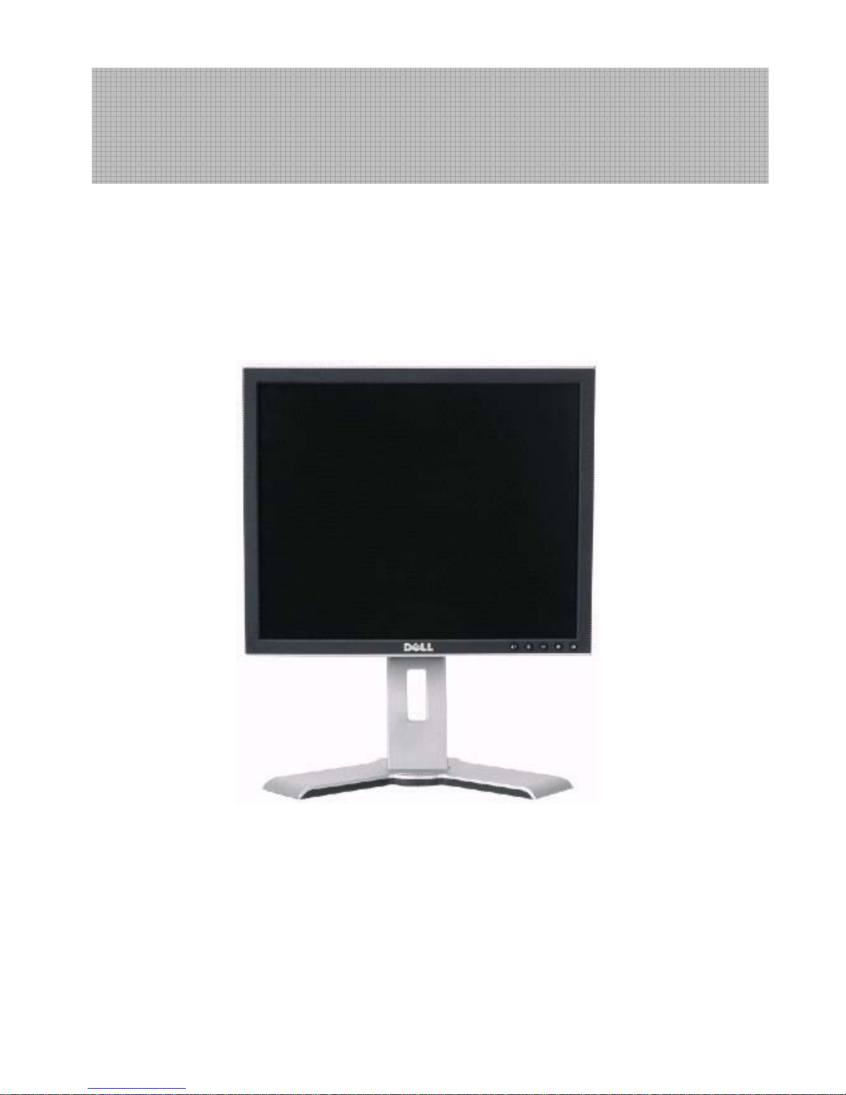
Dell 1707FPc
1
17” LCD MONITOR
DELL 1707FPc
THESE DOCUMENTS ARE FOR REPAIR SERVICE INFORMATION ONLY.EVERY REASONABLE EFFORT
HAS BEEN MADE TO ENSURE THE ACCURACY OF THIS MANUAL; WE CANNOT GUARANTEE THE
ACCURACY OFTHIS INFORMATION AFTER THE DATE OF PUBLICATION AND DISCLAIMS RELIABILITY FOR
CHANGES, ERRORS OR OMISSIONS.
Service Manual

Dell 1707FPc
2
Table of contents
Table of contents------------------------------------------------------------------------------------------------------------------------- 02
Revision List -------------------------------------------------------------------------------------------------------------------------------03
Important Safety Notice --------------------------------------------------------------------------------------------------------------- 04
1. Monitor Specifications -----------------------------------------------------------------------------------------------------------05
2. LCD Monitor Description ------------------------------------------------------------------------------------------------------- 06
3. Operation instructions --------------------------------------------------------------------------------------------------------------07
3.1 General Instructions ----------------------------------------------------------------------------------------------------07
3.2 Control buttons -------------------------------------------------------------------------------------------------------------07
3.3 Adjusting the Picture ---------------------------------------------------------------------------------------11
3.4 Connect Your Monitor ----------------------------------------------------------------------------------------------------------18
4. Input/Output Specification ---------------------------------------------------------------------------------------------------19
4.1 Input Signal Connector ----------------------------------------------------------------------------------------------------19
4.2 Factory Preset Display Modes ----------------------------------------------------------------------------------------- 20
4.3 Power Supply Requirements ---------------------------------------------------------------------------------------- 20
4.4 Panel Specification ---------------------------------------------------------------------------------------------------------- 21
5. Block Diagram ---------------------------------------------------------------------------------------------------------------------24
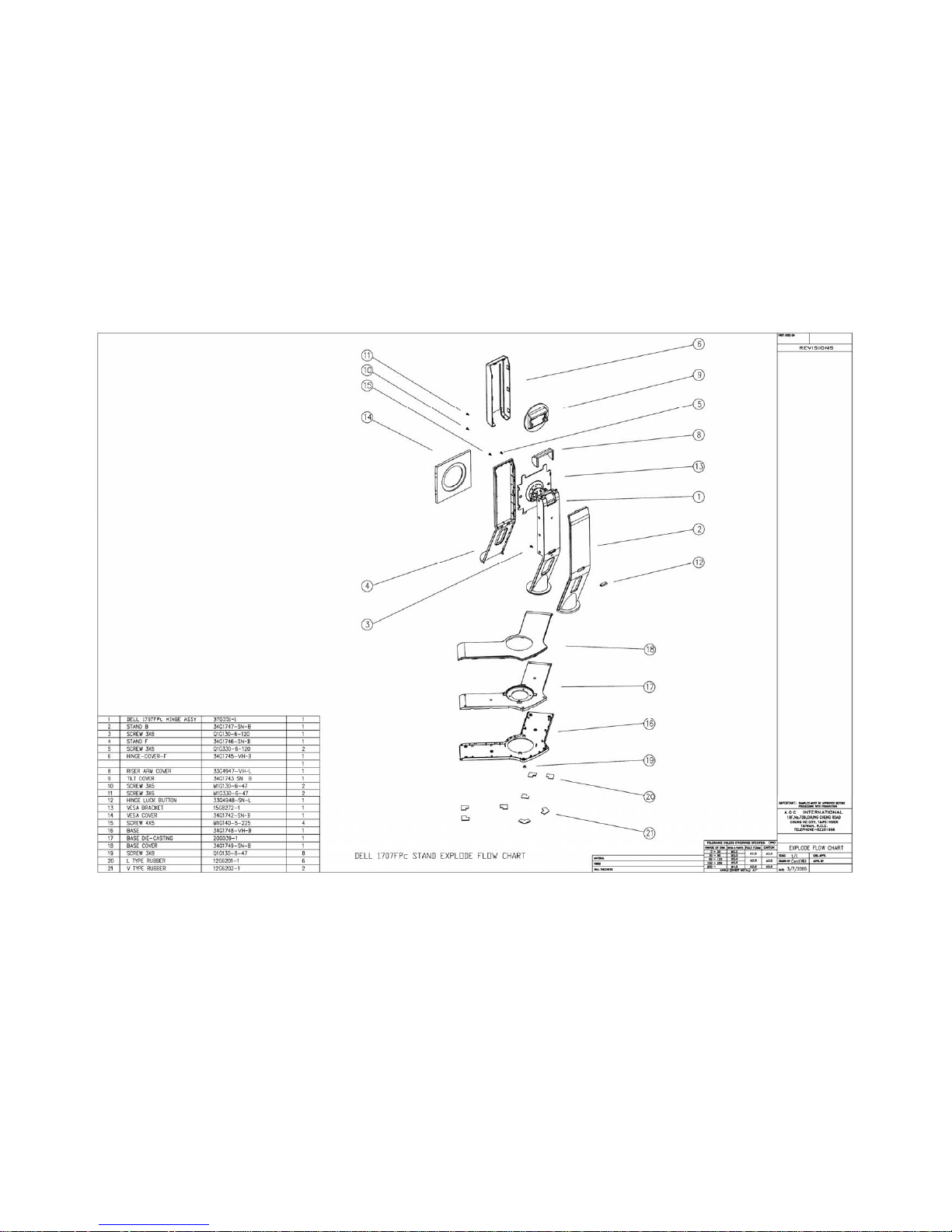
5.1 Monitor Exploded View ----------------------------------------------------------------------------------------------------24
5.2 Software Flow Chart ---------------------------------------------------------------------------------------------------------26
5.3 Electrical Block Diagram --------------------------------------------------------------------------------------------------28
6. Schematic Diagram -------------------------------------------------------------------------------------------------------------30
6.1 Main Board --------------------------------------------------------------------------------------------------------------------30
6.2 Power Board -------------------------------------------------------------------------------------------------------------------35
6.3 USB Board ------------------------------------------------------------------------------------------------------------------------37
7. Layout --------------------------------------------------------------------------------------------------------------------------- 39
7.1 Main Board --------------------------------------------------------------------------------------------------------------------- 39
7.2 Power Board ------------------------------------------------------------------------------------------------------------------- 40
7.3 USB Board ---------------------------------------------------------------------------------------------------------------------- 42
7.4 Key Board ---------------------------------------------------------------------------------------------------------------------- 42
8. Mechanical Instruction --------------------------------------------------------------------------------------------------------- 43
9. Maintainability -------------------------------------------------------------------------------------------------------------------- 52
9.1 Equipments and Tools Requirement -------------------------------------------------------------------------------- 52
9.2 Trouble Shooting ----------------------------------------------------------------------------------------------------------- 53
10. White Balance Adjustment --------------------------------------------------------------------------------------------------- 59
11. EDID Content -------------------------------------------------------------------------------------------------------------------- 61
12. ISP Instruction -------------------------------------------------------------------------------------------------------------- 62
12.1 Software Requirement and Connection -----------------------------------------------------------------------------62
12.2 Install the Software ---------------------------------------------------------------------------------------------------- 63
12.3 Running Program ------------------------------------------------------------------------------------------------------65
13. Check List -------------------------------------------------------------------------------------------------------------------------68
14. BOM List ------------------------------------------------------------------------------------------------------------------------------ 71
15. Definition Of Pixel Defects------------------------------------------------------------------------------------------------------126
16.Different Parts List-----------------------------------------------------------------------------------------------------------------132
Dell 1707FPc
3
Revision List
Revision Release Date Revise history TPV model
T780KSCDKRDFUP
T780KSCDKRDMUP
T780KGCHKRDEUP
A00 Nov.-28-2005 Initial Release
T780KGCHKRDMUP
A01 Dec.-22-2005
Sold area in EU and attach the corresponding
BOM
T780KSCHBRDEQP
A02 Mar.-28-2006 Add “Definition Of Pixel Defects”
A03 April-25-2006
Add” Max Brightness measurement ” on
Page 58
A04 Jun-22-2006 Add BOM in Item 14 T780KSCDKRDMUP
A05 Oct-14-2006 Add TPV Model in item 16 T780KGCHBRDEQCP
A06 Mar.-30-2007 Update Mechanical Instruction in item 8

Dell 1707FPc
4
Important Safety Notice
ANY PERSON ATTEMPTING TO SERVICE THIS CHASSIS MUST FAMILIARIZE HIMSELF WITH THE CHASSIS
AND BE AWARE OF THE NECESSARY SAFETY PRECAUTIONS TO BE USED WHEN SERVICING
ELECTRONIC EQUIPMENT CONTAINING HIGH VOLTAGES.
CAUTION: USE A SEPARATE ISOLATION TRANSFORMER FOR THIS UNIT WHEN SERVICING
REFER TO BACK COVER FOR IMPORTANT SAFETY GUIDELINGS
Important Safety Notice
Proper service and repair is important to the safe, reliable operation of all Dell Company** Equipment. The service
procedures recommended by Dell and described in this service manual are effective methods of performing
service operations. Some of these service operations require the use of tools specially designed for the purpose.
The special tools should be used when and as recommended.
It is important to note that this manual contains various CAUTIONS and NOTICES which should be carefully read
in order to minimize the risk of personal injury to service personnel. The possibility exists that improper service
methods may damage the equipment. It is also important to understand that these CAUTIONS and NOTICES ARE
NOT EXHAUSTIVE. Dell could not possibly know, evaluate and advise the service trade of all conceivable ways in
which service might be done or of the possible hazardous consequences of each way. Consequently, Dell has not
undertaken any such broad evaluation. Accordingly, a servicer who uses a service procedure or tool which is not
recommended by Dell must first satisfy himself thoroughly that neither his safety nor the safe operation of the
equipment will be jeopardized by the service method selected.
* * Hereafter throughout this manual, Dell Company will be referred to as Dell.
WARNING
Use of substitute replacement parts, which do not have the same, specified safety characteristics may create
shock, fire, or other hazards.
Under no circumstances should the original design be modified or altered without written permission from Dell. Dell
assumes no liability, express or implied, arising out of any unauthorized modification of design. Servicer assumes
all liability.
Take care during handling the LCD module with backlight unit
- Must mount the module using mounting holes arranged in four corners.
- Do not press on the panel, edge of the frame strongly or electric shock as this will result in damage to the
screen.
- Do not scratch or press on the panel with any sharp objects, such as pencil or pen as this may result in
damage to the Panel.
- Protect the module from the ESD as it may damage the electronic circuit (C-MOS).
- Make certain that treatment person’s body is grounded through wristband.
- Do not leave the module in high temperature and in areas of high humidity for a long time.
- Avoid contact with water as it may a short circuit within the module.
If the surface of panel becomes dirty, please wipe it off with a soft material. (Cleaning with a dirty or rough cloth
may damage the panel.)
FOR PRODUCTS CONTAINING LASER:
DANGER - Invisible laser radiation when open. AVOID DIRECT EXPOSURE TO BEAM.
CAUTION - Use of controls or adjustments or performance of procedures other than those
specified herein may result in hazardous radiation exposure.
CAUTION - The use of optical instruments with this product will increase eye hazard.
TO ENSURE THE CONTINUED RELIABILITY OF THIS PRODUCT, USE ONLY ORIGINAL
MANUFACTURER'S REPLACEMENT PARTS, WHICH ARE LISTED WITH THEIR PART
NUMBERS IN THE PARTS LIST SECTION OF THIS SERVICE MANUAL.

Dell 1707FPc
5
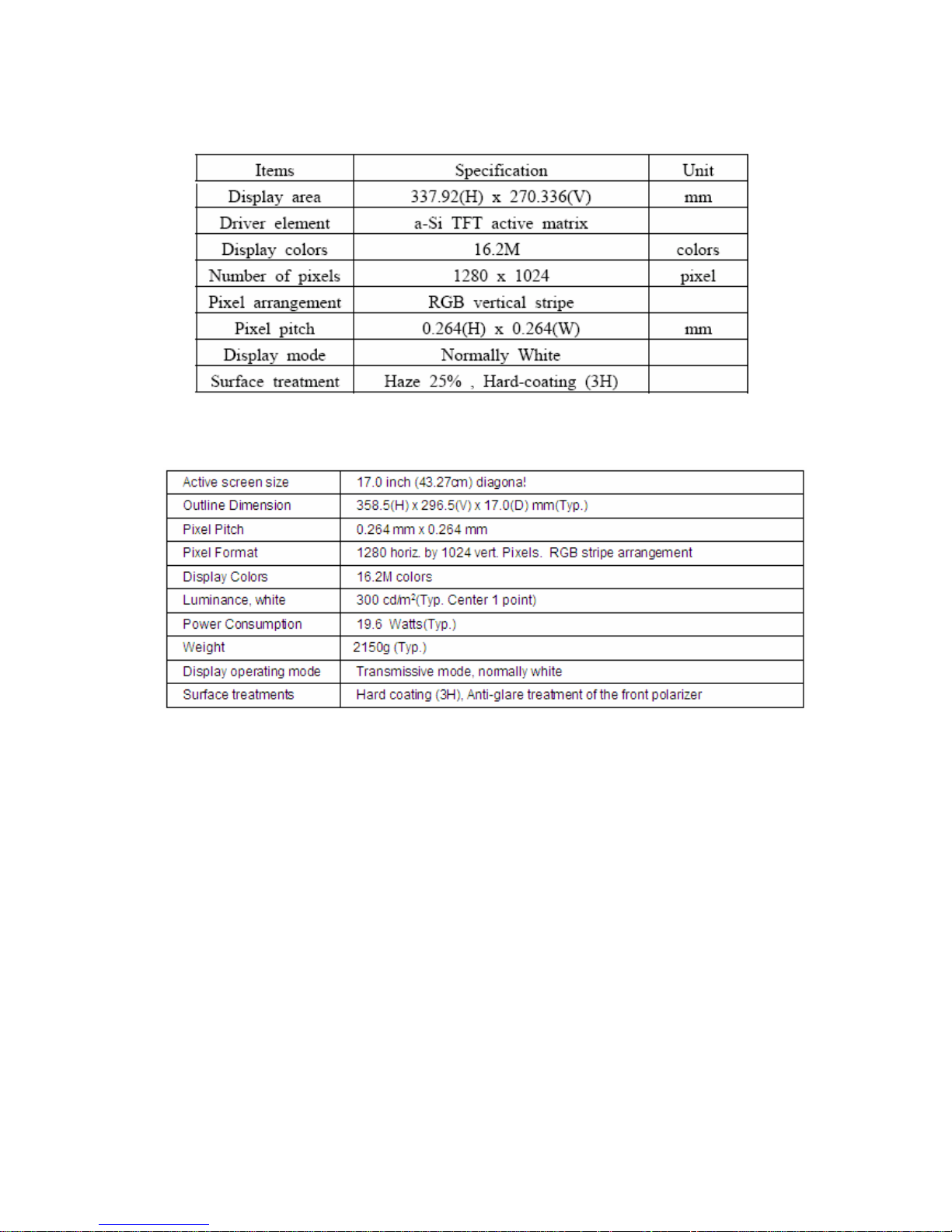
1. Monitor Specifications
Screen type Active matrix - TFT LCD
LTM170EU-L21 (SEC)
Panel Type
LM170E01-TLB4 (LPL)
Size 430mm(17.0")
Display Area 337.92(H) x 270.336(V)
Pixel pitch 0.264mm(H) x 0.264mm(V)
150(H) / 135(V) (type) (For LTM170EU-L21 panel)
Viewable angle (CR>=10)
140(H) / 140(V) (type) (For LM170E01-TLB4 panel)
LCD Panel
Response time 8ms(type)
Video R, G, B Analog Interface
Separate Sync H/V TTL
H-Frequency 30kHz – 81kHz
Input
V-Frequency 56 - 76Hz
Display Colors 16.2M Colors
Dot Clock 165MHz (Max)
Optimal preset resolution 1280 x 1024 at 60 Hz
Highest preset resolution 1280 x 1024 at 75 Hz
Plug & Play VESA DDC
ON Mode (with Dell
Sound bar and USB
active)
<65W
EPA ENERGY
STAR
®
OFF Mode <3W
Connector Type 15-pin D-subminiature, blue connector; DVI-D, white connector
Input Video Signal
Analog RGB, 0.7 Volts +/-5%, positive polarity at 75 ohm input
impedance
Power Source
100 V ~ 240 V± 10 %VAC, 50 ± 3Hz, 60 ± 3Hz
Temperature:
Operating: 5° to 35°C (41° to 95°F)
Non-operating: Storage: -20° to 60°C (-4° to 140°F); Shipping:
-20° to 60°C (-4° to 140°F)
Humidity:
Operating: 10% to 80%
Non-operating: Storage: 5% to 90%; Shipping: 5% to 90%
Environmental
Considerations
Altitude:
Operating: 3,657.6m (12,000 ft) max
Non*operating: 12,192 m (40,000 ft) max
Weight with packaging: 7.70 kg (16.98 lbs)
Weight with stand assembly and cables: 6.00 kg (13.23 lbs)
Weight without stand assembly: 4.14 kg (9.13 lbs)
Weight
Weight of stand assembly: 1.5 kg (3.31 lbs)
Dell 1707FPc
6
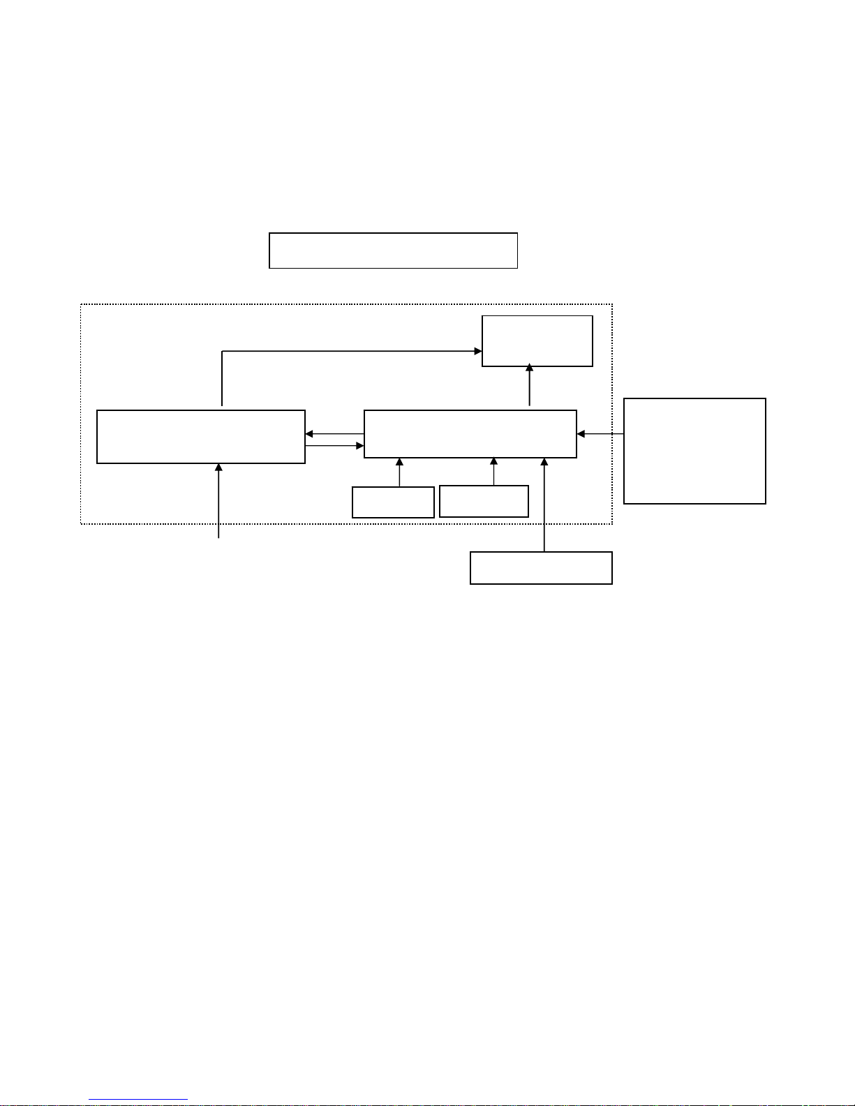
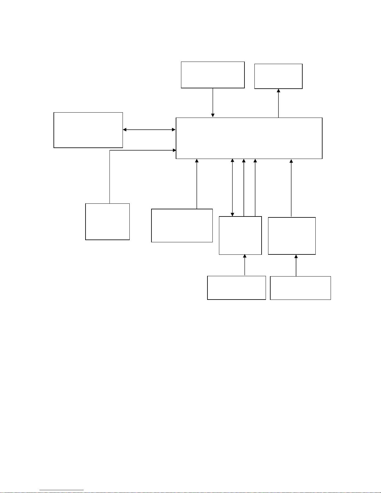
2. LCD Monitor Description
The LCD monitor will contain a main board, power board, key board, and USB board which house the flat panel
control logic, brightness control logic and DDC.
The power board will provide AC to DC Inverter voltage to drive the backlight of panel and the main board chips
each voltage.
Monitor Block Diagram
Video signal, DDC
Power board
(
Include: Inverter and adapter)
Flat Panel and
CCFL backlight
Main Board
Keyboard
RS232 Connector
For white balance
adjustment in factory
mode
CCFL Drive.
AC-IN
100-240V
HOST Computer
USB board
Dell 1707FPc
7
3. Operation instructions
3.1 General Instructions
Press the power button to turn the monitor on or off. The other control buttons are located at front panel
of the monitor. By changing these settings, the picture can be adjusted to your personal preferences.
-
The power cord should be connected.
-
Connect the video cable from the monitor to the video card.
-
Press the power button to turn on the monitor, the power indicator will light up.
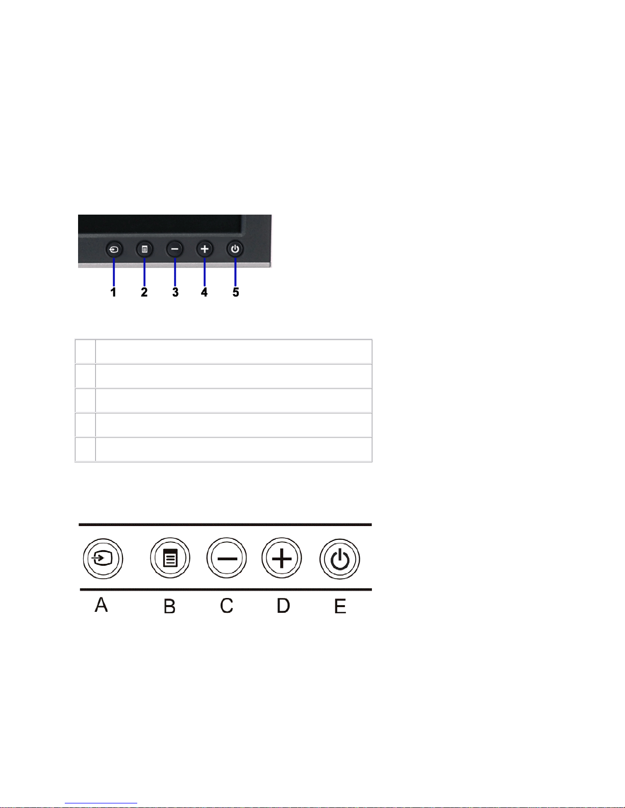
3.2 Control Buttons
1.
Input select
2.
OSD menu / select button
3.
Down button
4.
Up button
5.
Power button (with power light indicator)
Using the front panel
Use the buttons on the front of the monitor to adjust the image settings.
Dell 1707FPc
8
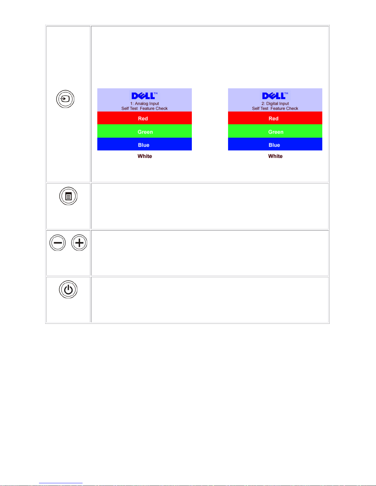
Input select
Use the Input Select button to select between two different video signals that may be
connected to your monitor.
NOTE: The floating 'Dell Self-test Feature Check' dialog appears on a black
background If the monitor cannot sense a video signal. Depending upon the
selected input, one of the dialogs shown below will scroll continually.
OSD menu /
select
The Menu button is used to open and exit the on-screen display (OSD), and exit from
menus and sub-menus.
Down (-) and
Up (+)
Use these buttons to adjust (decrease/increase ranges) items in the OSD menu.
Power Button
and Indicator
Use the power button to turn the monitor on and off.
The green light indicates the monitor is on, and fully functional. An amber light indicates
power save mode.
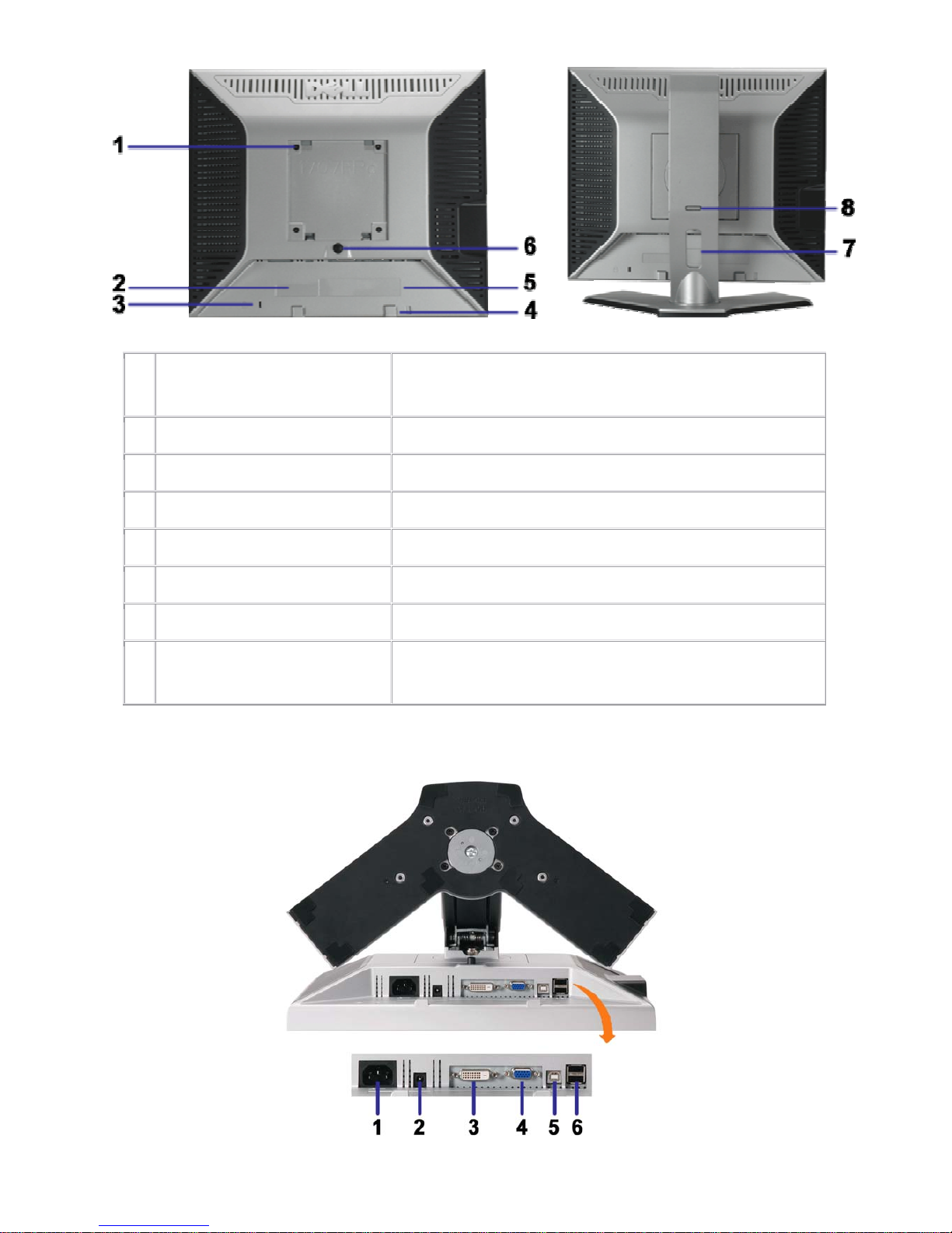
Back View
Dell 1707FPc
9
1
VESA mounting holes (100mm)
(Behind attached base plate)
Use to mount the monitor.
2 Barcode serial number label Refer to this label if you need to contact Dell for technical support.
3 Security lock slot Use a security lock with the slot to help secure your monitor.
4 Dell Soundbar mounting brackets Attach the optional Dell Soundbar.
5 Regulatory rating label List the regulatory approvals.
6 Stand removal button Press to release the stand
7 Cable holder Help organize cables by placing them in the holder.
8 Lock down/release button
Push the monitor down, press the button to unlock the monitor,
and then lift the monitor to the desired height.
Bottom View
Dell 1707FPc
10
1 Power connector Insert the power cable.
2 Dell Soundbar power connector Connect the power cord for the Soundbar (optional).
3 DVI connector Connect your computer DVI cable.
4 VGA connector Connect your computer VGA cable.
5 USB upstream connector
Connect the USB cable that came with your monitor to the monitor
and the computer. Once this cable is connected you can use the
USB connectors on the side and bottom of the monitor.
6 USB connector Connect your USB devices.
Side View
USB
connectors
(downstream)
Left side
Right side
Dell 1707FPc
11
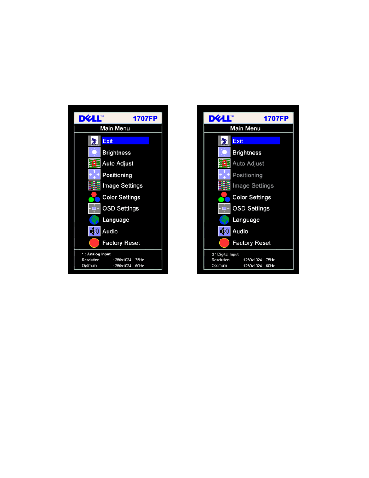
3.3 Adjusting the Picture
NOTE: If you change the settings and then either proceed to another menu, or exit the OSD menu, the
monitor automatically saves those changes. The changes are also saved if you change the settings and then
wait for the OSD menu to disappear.
Main Menu for Analog (VGA) Input Main Menu for Digital (DVI) Input
Or
NOTE: Positioning and Image Settings are only available when you are using the analog (VGA)
connector.
1. Push the MENU button to open the OSD menu and display the main menu.
2. Push the - and + buttons to move between the setting options. As you move from one icon to another,
the option name is highlighted. See the table below for a complete list of all the options available for the
monitor.
3. Push the MENU button once to activate the highlighted option.
4. Push - and + button to select the desired parameter.
5. Pus h MENU to enter the slide bar and then use the - and + buttons, according to the indicators on the
menu, to make your changes.
6. Push the MENU button once to return to the main menu to select another option or push the MENU button
two or three times to exit from the OSD menu.
Dell 1707FPc
12
Icon
Menu and
Submenus
Description
Exit
Select to exit the Main menu
Brightness/
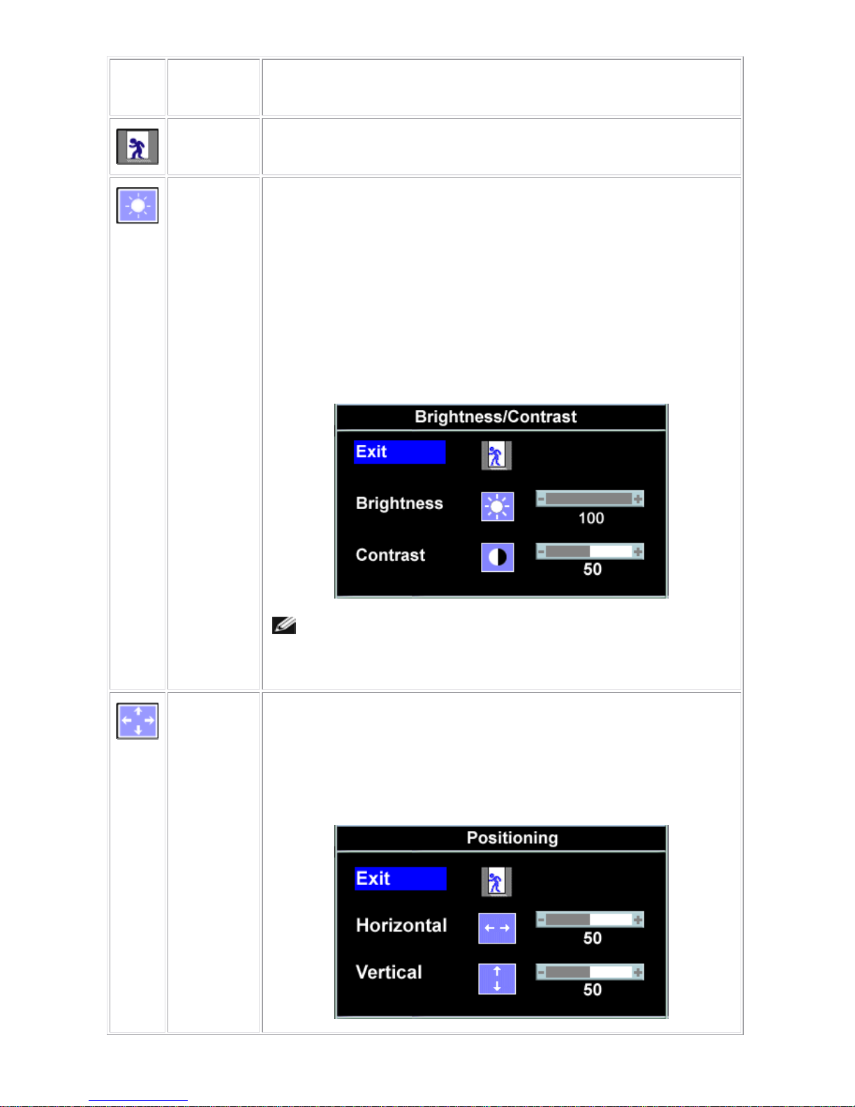
Contrast
Brightness adjusts the luminance of the backlight.
Adjust Brightness first, then adjust Contrast only if further adjustment is
necessary.
Push the + button to increase luminance and push the - button to decrease
luminance (min 0 ~ max 100).
Contrast adjusts the degree of difference between darkness and lightness on the
monitor screen.
Push the + button to increase the contrast and push the - button to decrease the
contrast (min 0 ~ max 100).
NOTE: When using DVI source, the contrast adjustment is not
available.
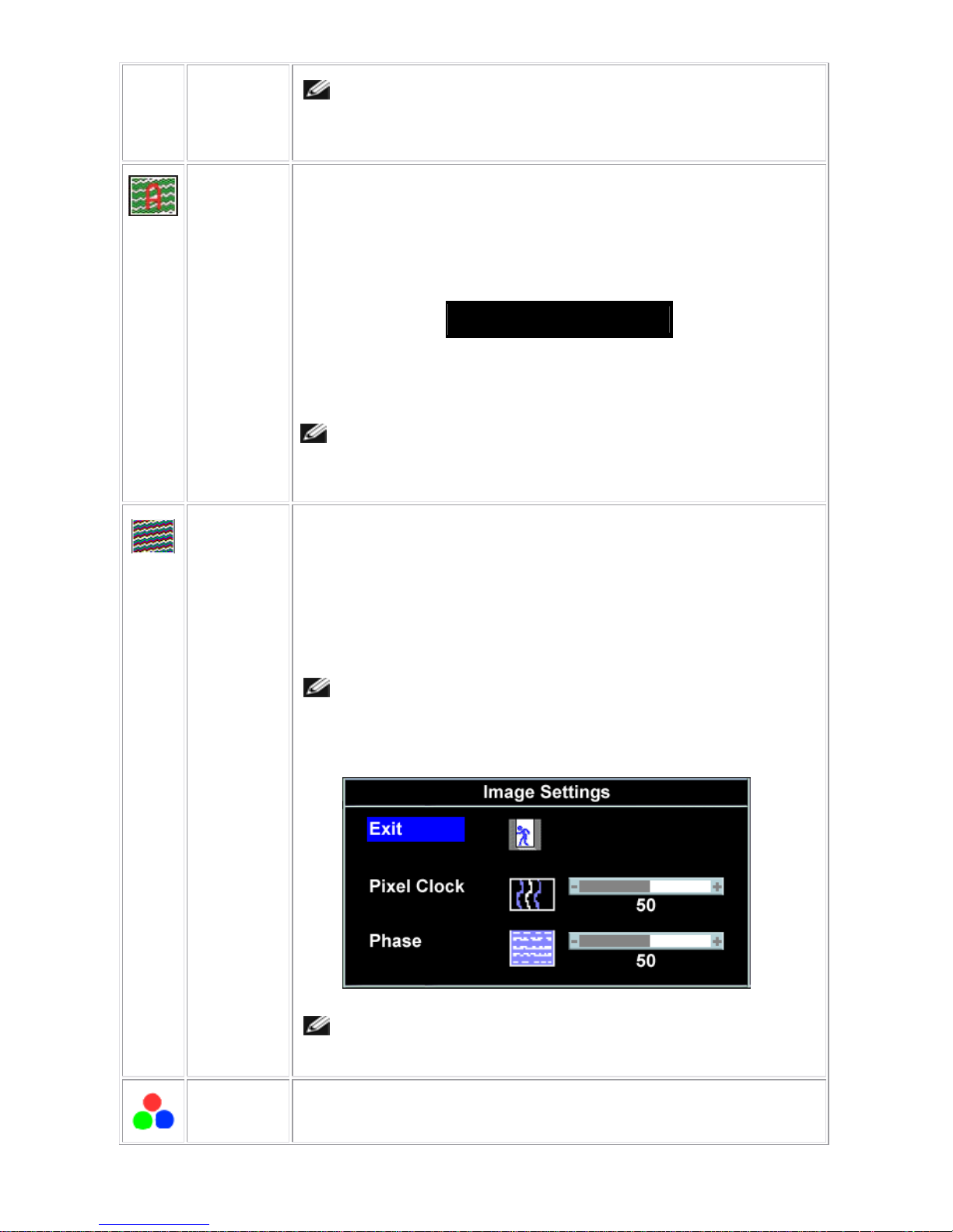
Positioning:
Horizontal
Vertical
Positioning moves the viewing area around on the monitor screen.
When making changes to either the Horizontal or Vertical settings, no changes
occur to the size of the viewing area. The image shifts in response to your
selection.
Minimum is 0 (-) and maximum is 100 (+).
Dell 1707FPc
13
NOTE: When using DVI source, the Positioning option is not
available.
Auto Adjust
Even though your computer recognizes your monitor on startup, the Auto
Adjustment function optimizes the display settings for use with your particular
setup.
Select to activate automatic setup and adjustment. The following dialog appears
on a black screen as the monitor self-adjusts to the current input:
Auto Adjust In Progress
Auto Adjustment allows the monitor to self-adjust to the incoming video signal.
After using Auto Adjustment, you can further tune your monitor by using the Pixel
Clock (Coarse) and Phase (Fine) controls under Image Settings.
In most cases, Auto Adjust produces the best image for your
configuration.
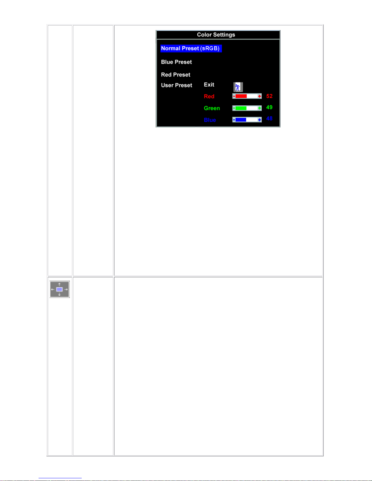
Image
settings:
Pixel Clock
(Coarse)
Phase (Fine)
The Phase and Pixel Clock adjustments allow you to more closely adjust your
monitor to your preference. These settings are accessed through the main OSD
menu, by selecting Image Settings.
Use the - and + buttons to make adjustments. (Minimum: 0 ~ Maximum: 100)
If satisfactory results are not obtained using the Phase adjustment, use Pixel
Clock (Coarse) and then use Phase (fine), again.
NOTE: This function may change the width of the display image.
Use the Horizontal function of the Position menu to center the
display image on the screen.
NOTE: When using DVI source, the Image Settings option is not
available.
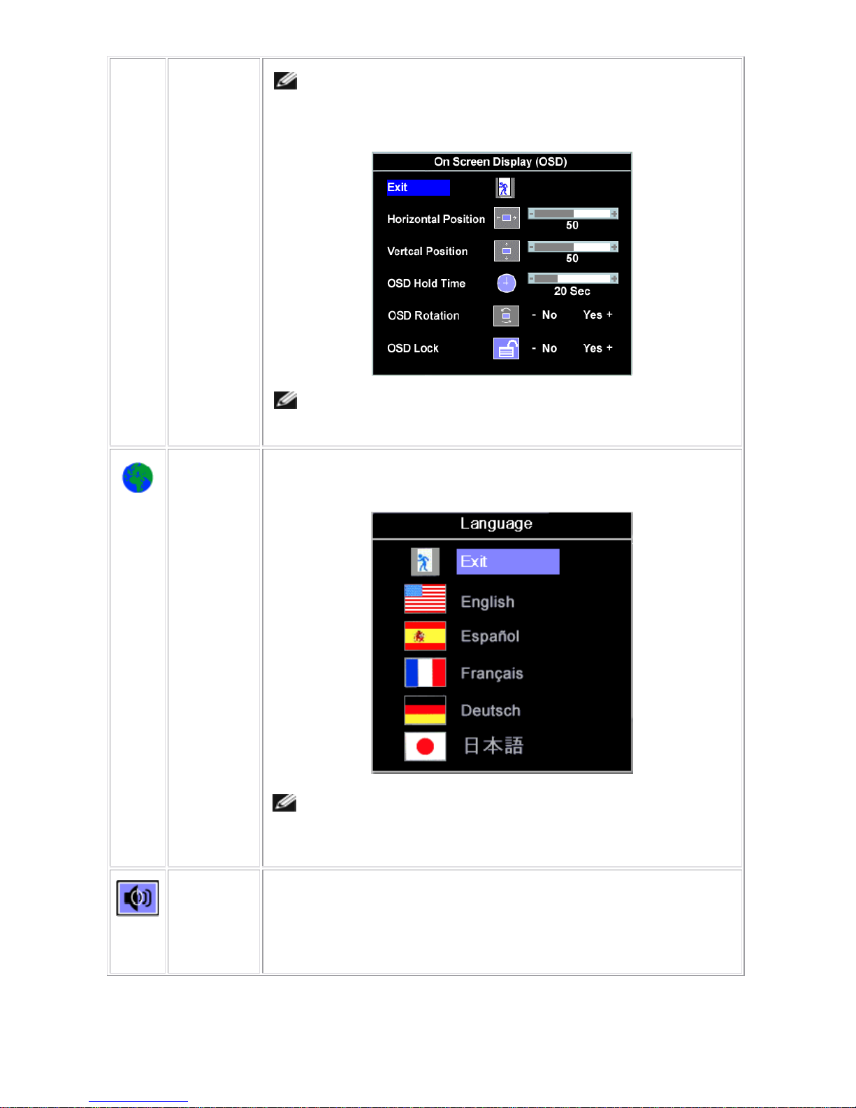
Color
Settings
Color Settings adjusts the color temperature, color hue, and saturation.
Dell 1707FPc
14
Blue Preset
Red Preset
Normal
Preset
User Preset
The color hue is most noticeable in areas of white.
• Blue Preset is selected to obtain a bluish tint. This color setting is
typically used for text based applications (spreadsheets, programming,
text editors, etc.).
• Red Preset is selected to obtain a redder tint. This color setting is
typically used for color-intensive applications (photograph image editing,
multimedia, movies, etc.).
• Normal Preset is selected to obtain the default (factory) color settings.
This setting is also the “sRGB” standard default color space.
• User Preset: Use the plus and minus buttons to increase or decrease
each of the three colors (R, G, B) independently, in single digit
increments, from 0 to 100.
OSD
Settings:
Horizontal
Position
Vertical
Position
OSD Hold
Time
Adjust the settings for the OSD, including the location, the amount of time the
menu remains on-screen, and the rotation of the OSD.
Position of the OSD:
• To adjust the horizontal position of the OSD, use the - and + buttons, and
move OSD to the left and right.
• To adjust the vertical position of the OSD, use the - and + buttons, and
move OSD down and up.
OSD Hold Time:
The OSD stays active for as long as it is in use. Adjusting the hold time, sets the
length of time the OSD remains active after the last time you pressed a button.
Use the - and + buttons to adjust the slider in 5 second increments, from 5 to 60
seconds.
OSD Lock:
Controls user access to adjustments. When Yes (+) is selected, no user
adjustments are allowed. All buttons are locked except the menu button.
Dell 1707FPc
15
OSD Lock
NOTE: When the OSD is locked, pressing the menu button takes the
user directly to the OSD settings menu, with OSD Lock selected.
Select No (-) to unlock and allow user access to all applicable settings.
NOTE: You can also lock or unlock the OSD by pushing and holding
the Menu button for 15 seconds.
Language
Select to have the OSD display in one of five languages (English, French,
Spanish, German, or Japanese).
NOTE: The change only affects the OSD. It has no effect on any
software running on the computer.
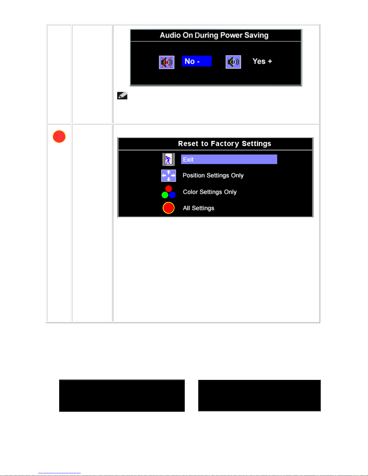
Audio
(optional)
You can select to have the audio on or off when the monitor is in power saving
mode.
Yes — enables audio
No — disables audio (default)
Dell 1707FPc
16
NOTE: When the Dell Soundbar is not properly connected to the
monitor, the audio menu is not available.
Factory
Reset:
Reset the OSD menu options to the factory-preset values.
Exit — Select to exit out of Reset to Factory Settings menu without resetting
any OSD options.
Position settings only — Change the settings for Image Position back to
original factory settings.
Color settings only — Change the Red, Green, and Blue settings
back to their original factory settings and set the default setting
for Normal Preset.
All settings — Change all the user-adjustable settings including color, position,
brightness, contrast and OSD hold time to the factory defaults. The language of
the OSD does not change.
OSD Warning Messages
One of the following warning messages may appear on the screen indicating that the monitor is out of
synchronization.
1. Analog Input
Cannot Display This Video Mode
Optimum Resolution 1280 x1024 60Hz
2. Digital Input
Cannot Display This Video Mode
Optimum Resolution 1280 x1024 60Hz
This means that the monitor cannot synchronize with the signal that it is receiving from the computer. Either
the signal is too high or too low for the monitor to use. See Specifications for the Horizontal and
Vertical frequency ranges addressable by this monitor. Recommended mode is 1280 X 1024 @ 60Hz.

Dell 1707FPc
17
NOTE: The floating Dell Self-test Feature Check dialog appears on-screen if the monitor cannot sense
a video signal.
Or
Occasionally, no warning message appears, but the screen is blank. This could also indicate that the monitor
is not synchronizing with the computer.
3.4 Connect Your Monitor
CAUTION: Before you begin any of the procedures in this section, follow the safety instructions.
Or
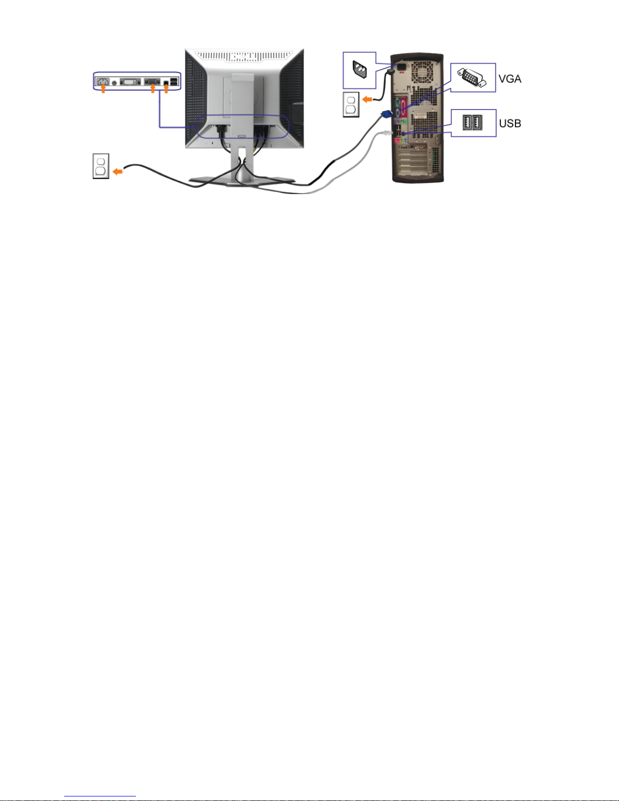
Dell 1707FPc
18
1. Turn off your computer and disconnect the power cable.
2. Connect either the white DVI or blue VGA cables to the connectors on the computer and the monitor.
3.
Connect the USB cable that was included with your monitor to the computer and the upstream USB connector
on the monitor. Once this cable is connected to the computer and the monitor, you can use the USB connectors
on the monitor.
4. Connect any USB devices.
5. Connect the power cables
6.
Turn on your monitor and computer. If you do not see an image, push the input select button and ensure the
correct input source is selected.
Dell 1707FPc
19
4. Input/Output Specification
4.1 Input Signal Connector
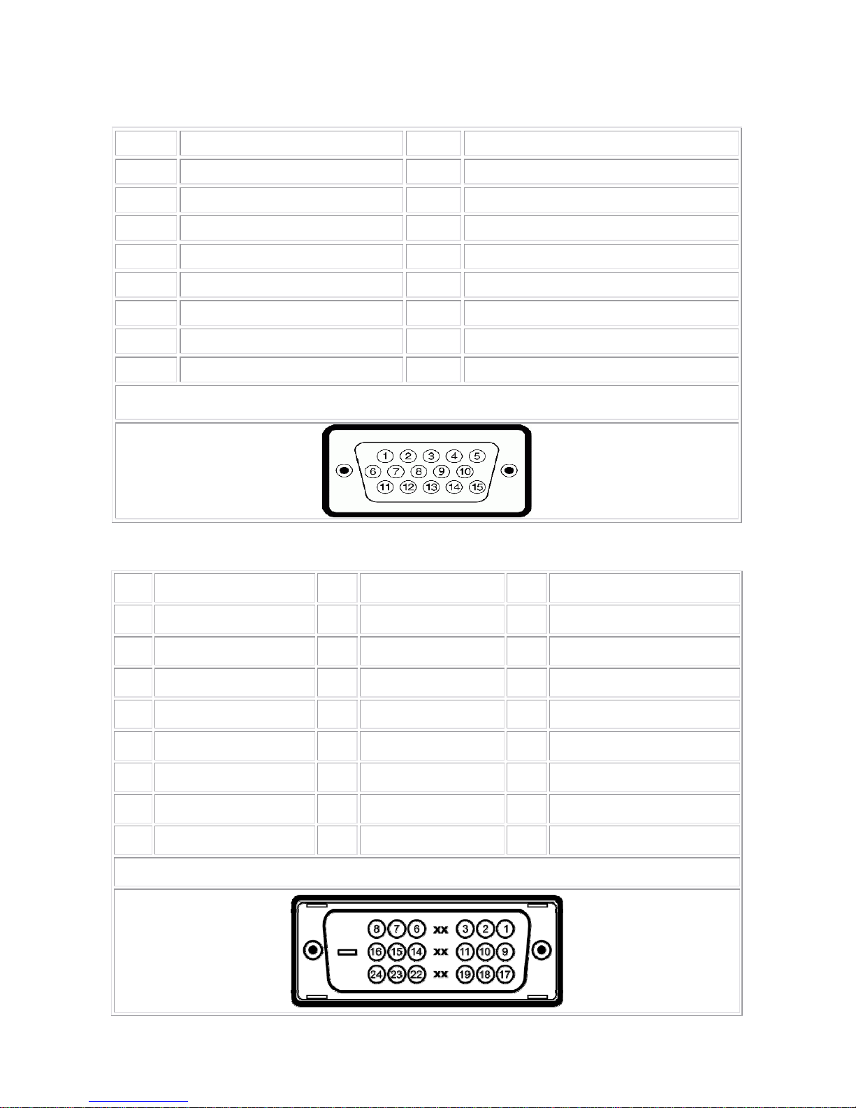
4.1.1 D-Sub Connector
Pin Signal Assignment Pin. Signal Assignment
1. Red Video 9. DDC +5V
2. Green Video 10. GND-Sync
3. Blue Video 11. GND
4. GND 12. DDC Data
5. Self Test 13. H-Sync
6. R-Ground 14. V-Sync
7. G-Ground 15. DDC Clock
8. B-Ground
VGA Connector layout
4.1.2 DVI Connector
Pin Signal Assignment Pin Signal Assignment Pin Signal Assignment
1 T.M.D.S. Data 2- 9 T.M.D.S. Data 1- 17 T.M.D.S. Data 0-
2 T.M.D.S. Data 2+ 10 T.M.D.S. Data 1+ 18 T.M.D.S. Data 0+
3 T.M.D.S. Data 2 Shield 11 T.M.D.S. Data 1 Shield 19 T.M.D.S. Data 0 Shield
4 No Pin 12 No Pin 20 No Pin
5 No Pin 13 No Pin 21 No Pin
6 DDC Clock 14 +5V Power 22 T.M.D.S. Clock Shield
7 DDC Data 15 Ground (for +5V) 23 T.M.D.S. Clock +
8 No Connect 16 Hot Plug Detect 24 T.M.D.S. Clock -
DVI Connector Layout
Dell 1707FPc
20
4.2 Factory Preset Display Modes
Display Mode
Horizontal
Frequency (kHz)
Vertical
Frequency (Hz)
Pixel Clock
(MHz)
Sync Polarity
(Horizontal/Vertical)
VESA, 720 x 400 31.5 70.0 28.3 -/+
VESA, 640 x 480 31.5 60.0 25.2 -/-
VESA, 640 x 480 37.5 75.0 31.5 -/-
VESA, 800 x 600 37.9 60.3 49.5 +/+
VESA, 800 x 600 46.9 75.0 49.5 +/+
VESA, 1024 x 768 48.4 60.0 65.0 -/-
VESA, 1024 x 768 60.0 75.0 78.8 +/+
VESA, 1152 x 864 67.5 75.0 108 +/+
VESA, 1280 x 1024 64.0 60.0 135.0 +/+
VESA, 1280 x 1024 80.0 75.0 135.0 +/+
4.3 Power Supply Requirements
A/C Line voltage range : 100 V ~ 240 V
A/C Line frequency range
: 50 ± 3Hz, 60 ± 3Hz
Current : 1.5A max at 100V; 0.8A max at 240 V
Peak surge current : < 60A peak at 240 VAC and cold starting
Leakage current : < 3.5mA
Power line surge : No advance effects (no loss of information or defect)
with a maximum of 1 half-wave missing per second
DC output Voltage
: 5VDC ± 5%; 12VDC± 5%
Dell 1707FPc
21
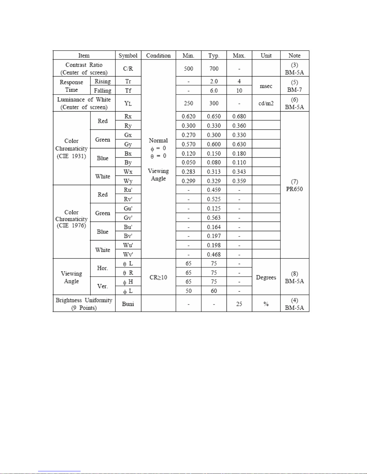
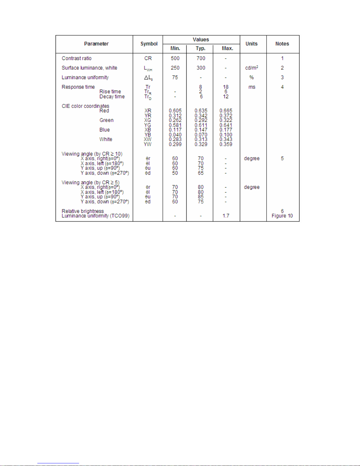
4.4 Panel Specification
4.4.1 Display Characteristics
For LTM170EU - L21 panel
For LM170E01-TLB4 panel
Dell 1707FPc
22
4.4.2 Optical Characteristics
For LTM170EU - L21 panel
Dell 1707FPc
23
For LM170E01-TLB4 panel
Dell 1707FPc
24
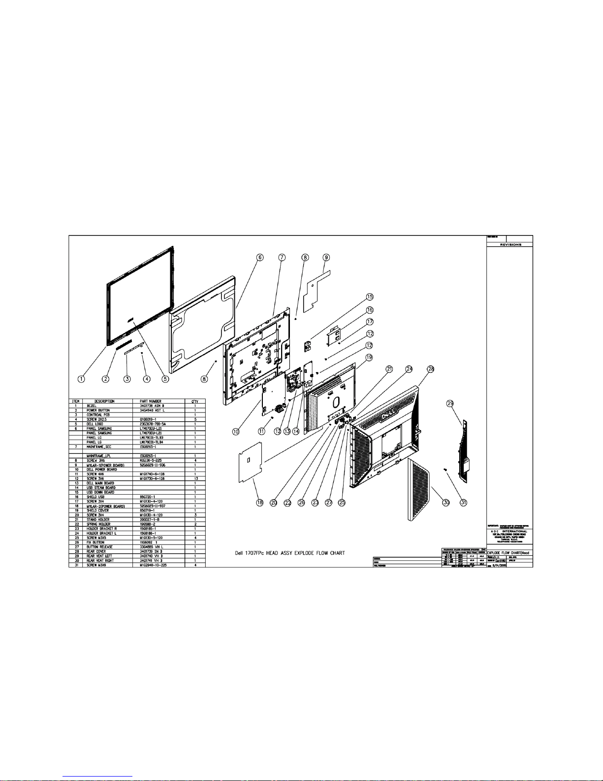
5. Block Diagram
5.1 Monitor Exploded View
Dell 1707FPc
25
Dell 1707FPc
26
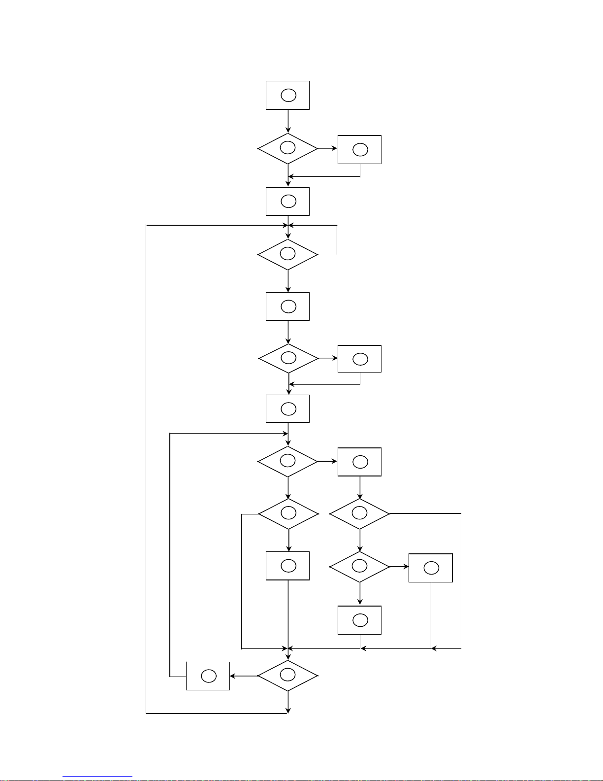
5.2 Software Flow Chart
1
2
N
Y
5
Y
N
10
Y
N
12
Y
N
7
Y
N
6
4
3
8
9
14
11
13
Y
N
15
Y
N
16
17
19
Y
N
18

Dell 1707FPc
27
1) MCU Initializes.
2) Is the EEprom blank?
3) Program the EEprom by default values.
4) Get the PWM value of brightness from EEprom.
5) Is the power key pressed?
6) Clear all global flags.
7) Are the AUTO and SELECT keys pressed?
8) Enter factory mode.
9) Save the power key status into EEprom.
Turn on the LED and set it to green color. Scalar
initializes.
10) In standby mode?
11) Update the lifetime of back light.
12) Check the analog port, are there any signals coming?
13) Does the scalar send out an interrupt request?
14) Wake up the scalar.
15) Are there any signals coming from analog port?
16) Display "No connection Check Signal Cable" message. And go into standby mode after the message
disappears.
17) Program the scalar to be able to show the coming mode.
18) Process the OSD display.
19) Read the keyboard. Is the power key pressed?
Dell 1707FPc
28
5.3 Electrical Block Diagram
5.3.1 Main Board
OSD Control
Interface
(CN403)
Scalar GM5621
(Include MCU, ADC, OSD)
(U401)
Flash Memory
PM25LV010-25SCE
(U402)
EEPROM
M24C16-WMN6TP
(U403
)
D-Sub
Connector
(CN202)
EEPROM (U202)
M24C02-WMN6TP
R
G
B
RXD
TXD
DB15_SDA,
DB15_SCL
EPR_SDA
EPR_SCL
LCD Interface
(CN501)
H
V
DVI
Connector
(CN201)
EEPROM (U201)
M24C02-WMN6TP
X301
CRYSTAL
14.318MHzHC-49U
Dell 1707FPc
29
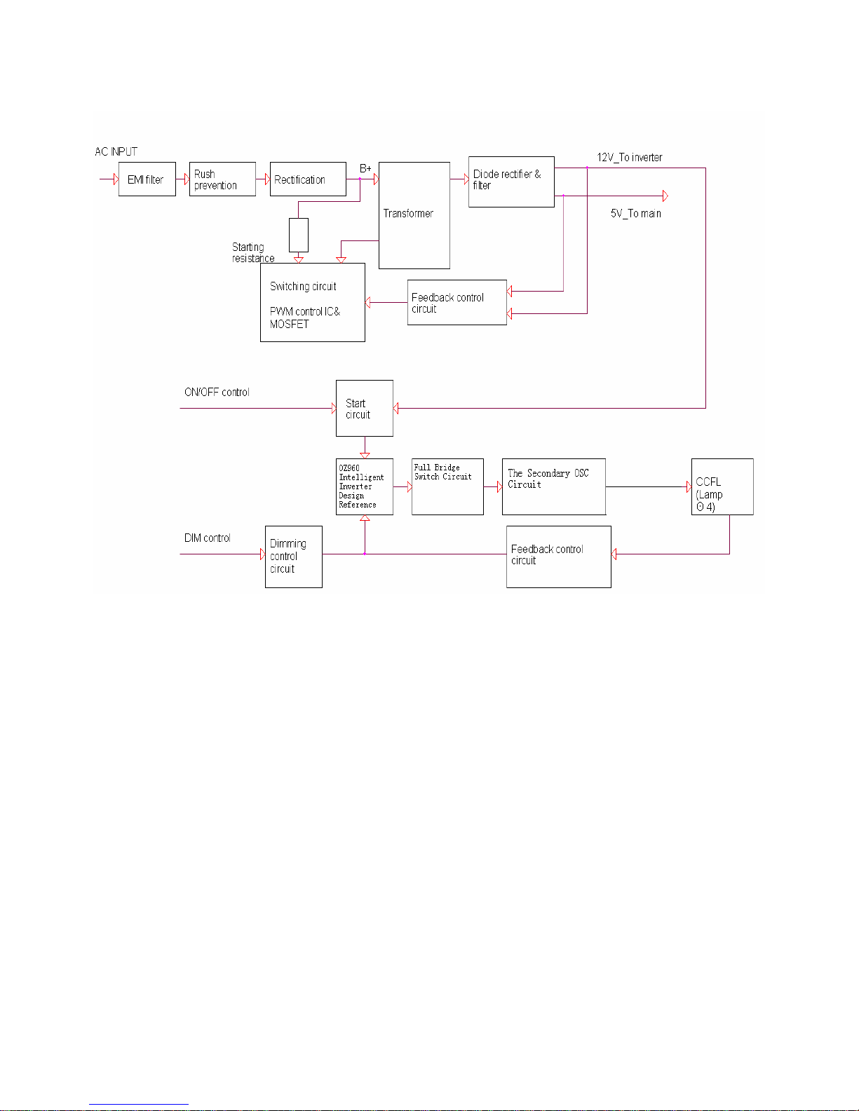
5.3.2 Inverter/Power Board
Dell 1707FPc
30
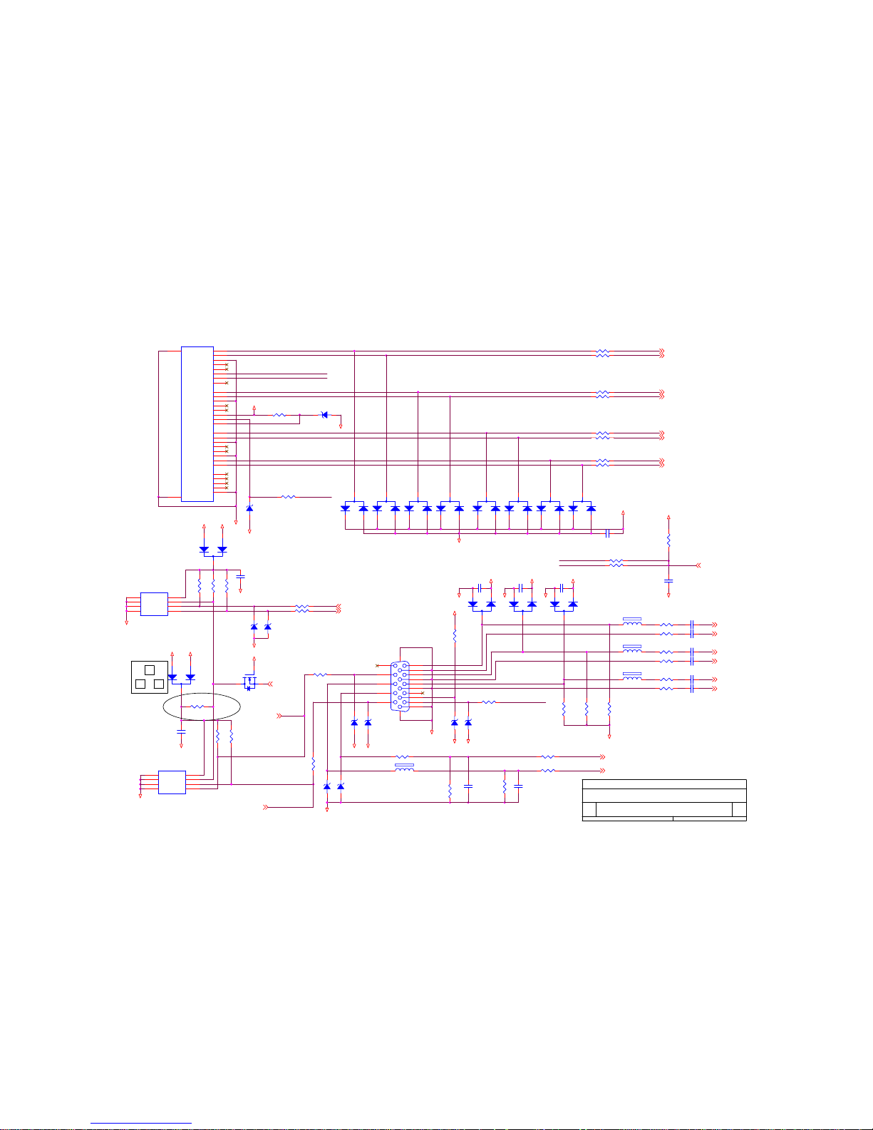
6. Schematic Diagram
6.1 Main Board
GND
GND
RX1-IN
RX0+IN
R240
2.2K 1/16W
VGA_5V
R210
220 1/16W
DVI_HPD
R244
10K 1/16W
RX2- (3)
+5V
DDC_SDA_A
R237 220 1/16W
C217
22pF
C216
0.01uF
GND
SCL_IN
GND
R216 220 1/16W
+5V
CABLE_DET (3)
C218
22pF
D208
BAV99
3
1
2
DVI_5V
D211
BAV99
3
1
2
R203 10 1/16W
D212
BAV99
3
1
2
R242
4.7K 1/16W
GND
R218 33K 1/16W
+5V
RX1+ (3)
D210
BAV70
3
1
2
GND
GND
RXC+ (3)
RX0- (3)
R212
4.7K 1/16W
ZD210
UDZS5.6B
R214
10K 1/16W
C212
0.01uF
GND
VGA_PLUG
R217 22K 1/16W
+5V
RXC- (3)
ZD212
UDZS5.6B
R239 220 1/16W
VGA_5V
HS_in
GND
R209 10 1/16W
R228 220 1/16W
Pins 6/7/8 are R/G/B
return lines resp.
VGA_PLUG
ZD204
UDZS5.6B
HS (3)
R232
220 1/16W
RED- (3)
RX2+IN
R238 220 1/16W
D205
BAV99
3
1
2
DVI_5V
R227
4.7K 1/16W
C219
0.1uF/16V
RX0+ (3)
Bin
2
DVI_HPD
U201
M24C02WMN6
4
81
2
3
7
6
5
GND
VCCA0
A1A2WP
SCL
SDA
D201
BAV99
3
1
2
DDC_SCL_A
D203
BAV99
3
1
2
D209
BAV70
3
1
2
RX0-IN
RXC+IN
R243 0 1/16W
R206 10 1/16W
GND
D207
BAV99
3
1
2
BLUE- (3)
R222
100 1/16W
C210
0.01uF
GND
ZD209
UDZS5.6B
FB202
60 OHM
R213
4.7K 1/16W
C213
0.01uF
R205 10 1/16W
R201 10K 1/16W
RX1- (3)
R233
75 1/16W
C220
0.1uF/16V
E
Input Connectors
26Monday, November 14, 2005
Dell 1707FPc
Title
Size Document Number Rev
Date: Sheet
of
+3.3V_VDD
VS (3)
GND
FB201
60 OHM
GND
R207 10 1/16W
RX2+ (3)
C209
0.1uF/16V
(10 mil,
┰キ︽絬
)
BLUE+ (3)
D206
BAV99
3
1
2
ZD208
UDZS5.6B
DDC_SCL_VGA(3)
DDC_SDA_VGA(3)
RED+ (3)
R241
2.2K 1/16W
R224
100 1/16W
C215
0.01uF
R208 10 1/16W
Q201
2N7002E
3D
1
G
2
S
GND
RXC-IN
8/16
GREEN- (3)
C221
0.1uF/16V
D213
BAV99
3
1
2
R223
75 1/16W
ZD211
UDZS5.6B
+5V
C211
0.01uF
SCL_IN
R220
75 1/16W
C222
0.1uF/16V
Rin
R235
75 1/16W
GND
R202 10 1/16W
CN201
JACK
1
2
3
4
5
6
7
8
9
10
11
12
13
14
15
17
18
19
20
21
23
24
C1
16
22
C2
C3
C4
C5
25
26
T2-
T2+
SGND
T4-
T4+
DDCCLK
DDCDAT
A_VSYNC
T1-
T1+
SGND
T3T3+
+5V
GND
T0T0+
SGND
T5T5+
TC+
TC-
A_RED
HPD
SGND
A_GREEN
A_BLUE
A_HSYNC
A_GND
A_GND
A_GND
75-ohm terminating resistor
very close to the VGA
conn.
GND
GND
RX2-IN
RX1+IN
R229
75 1/16W
SDA_IN
GND
FB203
60 OHM
R211
10K 1/16W
R204 10 1/16W
GND
VS_IN
HOT_PLUG
ZD201
UDZS5.6B
(8 mil)
+5V
GND
R230
100 1/16W
SDA_IN
ZD203
UDZS5.6B
R226
4.7K 1/16W
DDC_SCL_DVI (3)
GREEN+ (3)
U202
M24C02WMN6
4
81
2
3
7
6
5
GND
VCCA0
A1A2WP
SCL
SDA
ZD207
UDZS5.6B
3
+5V
DVI_EDID_WP
(3)
DDC_SDA_DVI (3)
FB204
430 OHM
ZD202
UDZS5.6B
D204
BAV99
3
1
2
Gin
R234
75 1/16W
R215 220 1/16W
C214
0.1uF/16V
1
CN202
DB15
1
6
2
7
3
8
4
9
5
11
12
13
14
15
10
1716
C201
1000pF
D202
BAV99
3
1
2
 Loading...