

Dell 1704FPV User guide
Dell™ 1704FPV Flat Panel Monitor
About Your Monitor
Front View
Back View
Side View
Bottom View
Monitor Specifications
Dell Soundbar (Optional) Specifications
Caring for Your Monitor
Using Your Adjustable Monitor Stand
Attaching the Stand
Organizing Your Cables
Using the Tilt, Swivel, Vertical Extension
Removing the Stand
Setting Up Your Monitor
Connecting Your Monitor
Using the Front Panel Buttons
Using the OSD
Setting the Optimal Resolution
Using the Dell Soundbar (Optional)
Rotating Your Monitor
Changing the Rotation of Your Monitor
Rotating Your Operating System
Solving Problems
Troubleshooting Your Monitor
General Problems
Product Specific Problems
USB Problems
Troubleshooting Your Soundbar
Appendix
Warranty
Safety Information
Contacting Dell
Regulatory Notices
Recycling
Your Monitor Set-up Guide
Information in this document is subject to change without notice.
© 2004 Dell Inc. All rights reserved.
Reproduction in any manner whatsoever without the written permission of Dell Inc. is strictly forbidden.
Trademarks used in this text: Dell™, PowerEdge™, PowerConnect™, PowerVault™, Dell™ Dimension™, Inspiron™, OptiPlex™, Latitude™, Dell
Precision™ and Dell | EMC are trademarks of Dell Inc; Microsoft, Windows and Windows NT are registered trademarks of Microsoft
Corporation; Adobe is a trademark of Adobe Systems Incorporated, which may be registered in certain jurisdictions. ENERGY STAR is a registered
trademark of the U.S. Environmental Protection Agency. As an ENERGY STAR partner, Dell Inc. has determined that this product meets the ENERGY
STAR guidelines for energy efficiency. EMC is a registered trademark of EMC Corporation.
Other trademarks and trade names may be used in this document to refer to either the entities claiming the marks and names or their products.
Dell Inc. disclaims any proprietary interest in trademarks and trade names other than its own.
August 2004
Back to Contents Page
About Your Monitor
Dell™ 1704FPV Flat Panel Monitor
Front View
Back View
Bottom View
Side View
Monitor Specifications
Dell Soundbar (Optional) Specifications
Caring for Your Monitor
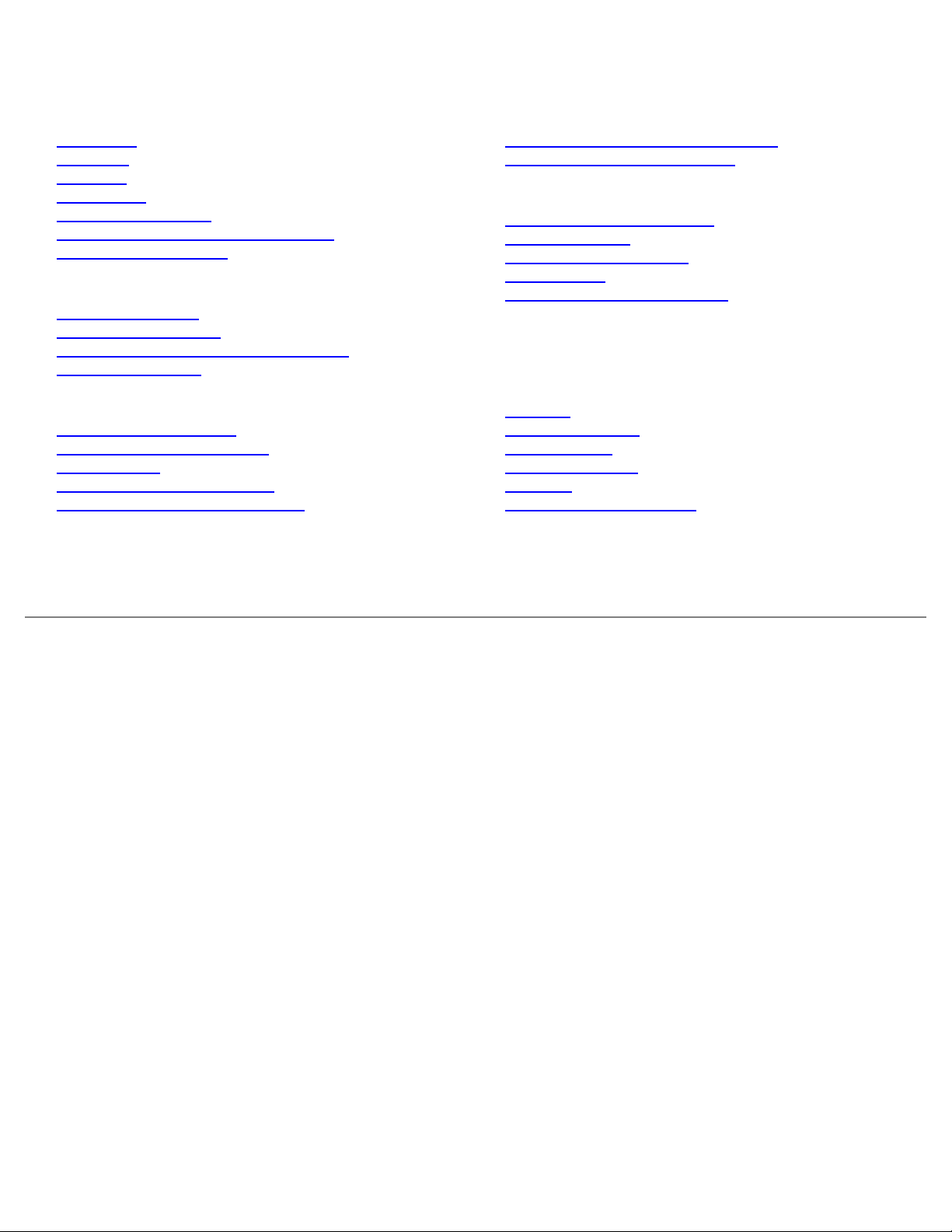
Front View
1. OSD menu / select button
2. Input select / down button
3. Auto-adjust / up button
4. Power button (with power light indicator)
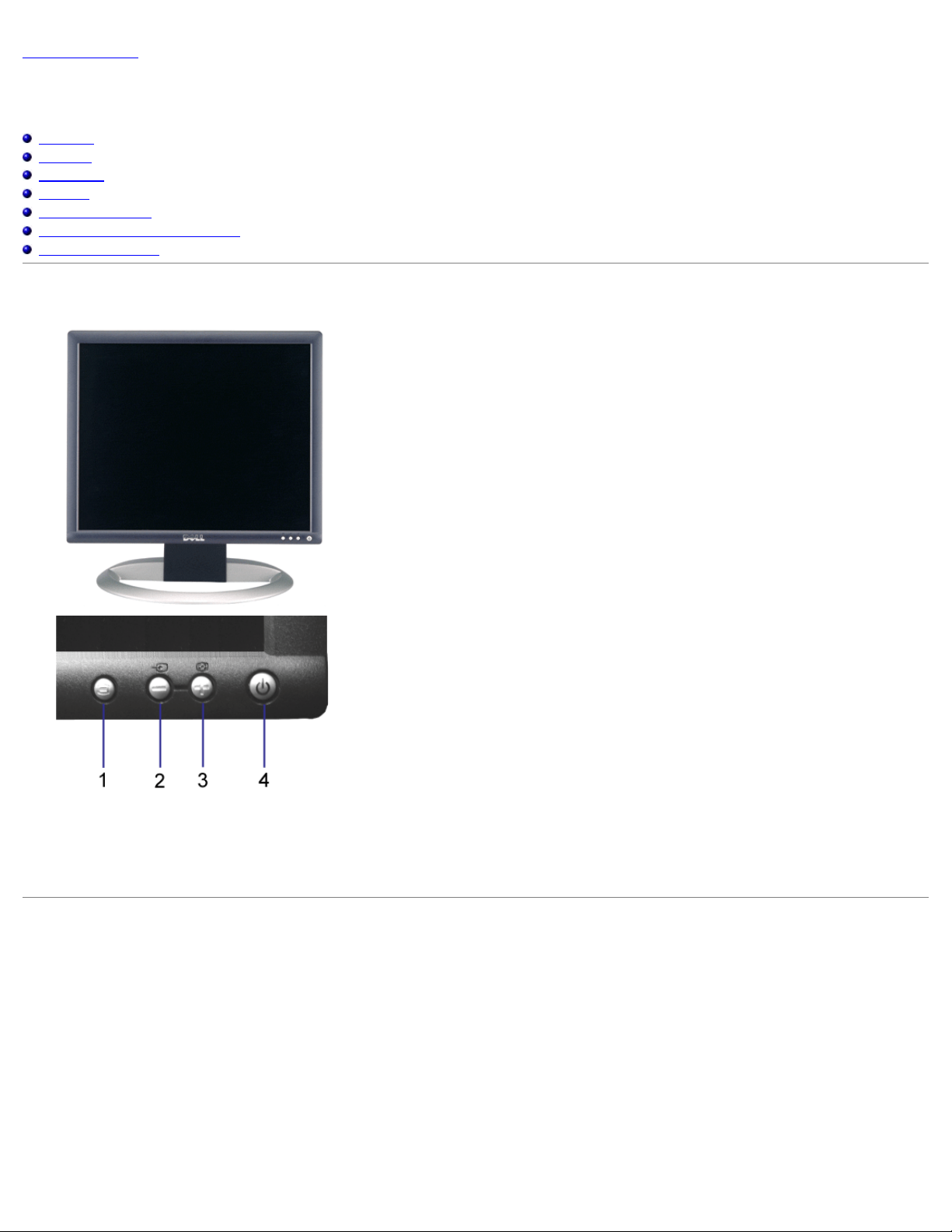
Back View
1. Dell Soundbar mounting brackets — Attach the optional Dell Soundbar.
2. Security lock slot — Attach a lock to secure your monitor.
3. Stand removal button — Press to release the stand.
4. VESA mounting holes (100mm [Behind attached base plate]) — Use to mount the monitor.
5. Barcode serial number label — Refer to this label if you need to contact Dell for technical support
6. Lock down/release button — Push the monitor down, press the button to unlock the monitor, and then lift the monitor to the desired height.
7. Regulatory rating label — Lists the regulatory approvals.
8. Cable holder — Help organize cables by placing them in the holder.
Bottom View
1. Power connector - Connect the power cable
2. Dell Soundbar power connector - Connect the power cord for the Soundbar (optional)
3. DVI connector - Connect your computer DVI cable
4. VGA connector - Connect your computer VGA cable
USB upstream connector - Connect the USB cable that came with your monitor to the monitor and the computer. Once this cable is connected you can use the USB
5.
connectors on the side and bottom of the monitor.
USB connector - Connect your USB devices. You can only use this connector after you have connected the USB cable to the computer and USB upstream connector on
6.
the monitor.
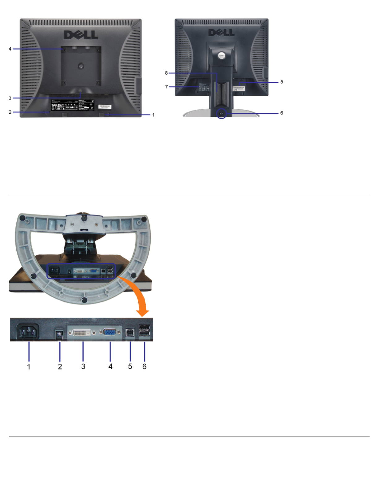
Side View
USB connectors (downstream)
Left side Right side
Monitor Specifications
Power Management Modes
If you have VESA's DPM™ compliance display card or software installed in your PC, the monitor can automatically reduce its power consumption when not in use. This is
referred to as 'Power Save Mode'*. If input from keyboard, mouse or other input devices is detected by the computer, the monitor will automatically "wake up". The following
table shows the power consumption and signaling of this automatic power saving feature:
VESA Modes Horizontal Sync Vertical Sync Video Power Indicator Power Consumption
Normal operation( with Dell Soundbar and USB active) Active Active Active Green 65 W (maximum)
Normal operation Active Active Active Green 32 W (typical)
Active-off mode Inactive Inactive Blanked Amber Less than 3 W
Switch off - - - Off Less than 1 W
NOTE: The OSD will only function in the 'normal operation' mode. Otherwise one of the following messages will
appear when the “menu” or “plus” buttons are pressed when in Active-off mode.
1. Analog Input
Press Any Key on Keyboard or Move Mouse
This monitor is ENERGY STAR®-compliant as well as TCO '99 / TCO '03 power management compatible.
* Zero power consumption in OFF mode can only be achieved by disconnecting the main cable from the monitor.
ENERGY STAR® is a U.S. registered mark. As an ENERGY STAR® Partner, DELL has determined that this product meets the ENERGY STAR® guidelines for energy
efficiency.
In Power Save Mode
Activate the computer and 'wake up' the monitor to gain access to the OSD
or
Press Any Key on Keyboard or Move Mouse
2. Digital Input
In Power Save Mode
.
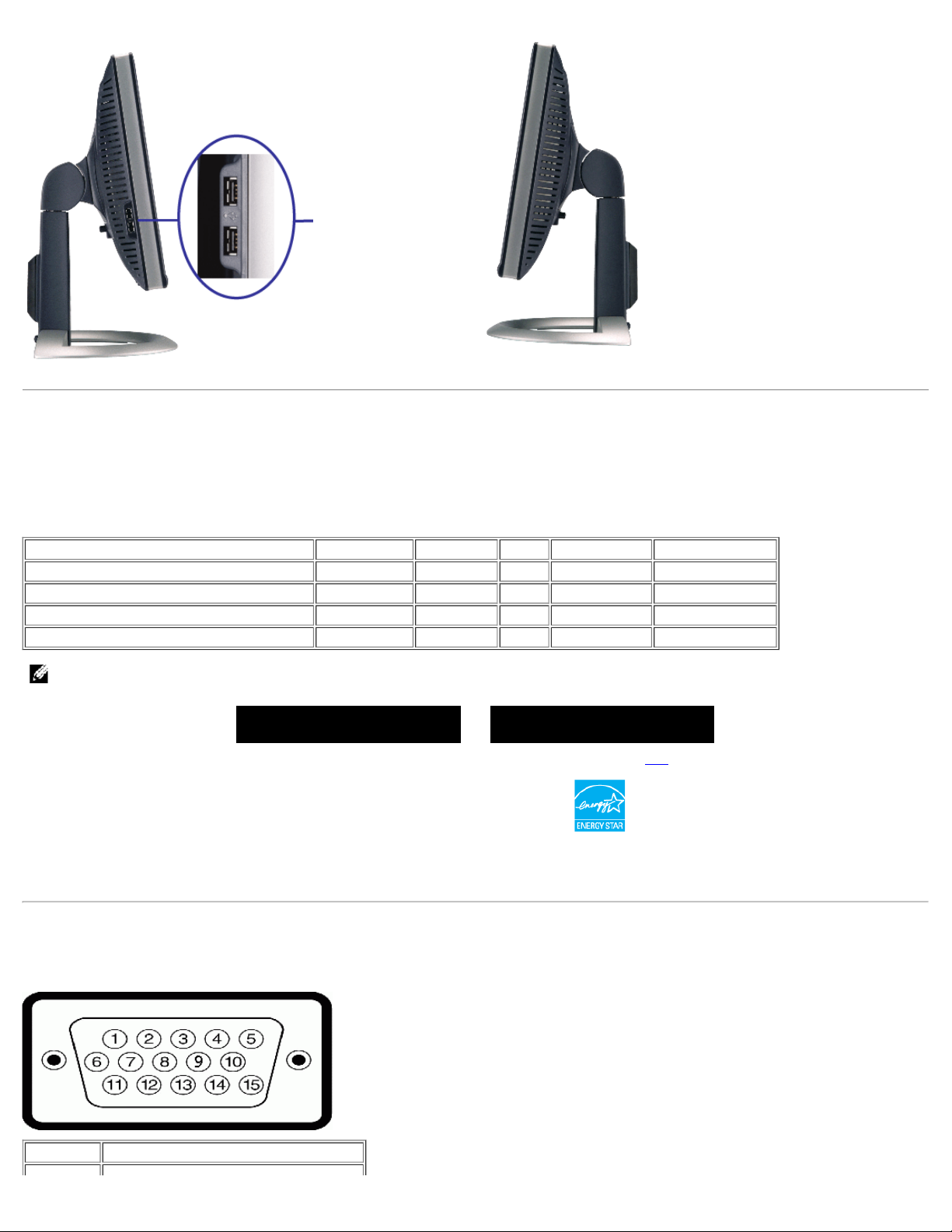
Pin Assignments
15-pin D-Sub connector:
Pin Number Monitor Side of the 15-Pin Side Signal Cable
1 Video-Red
2 Video-Green
3 Video-Blue
4 GND
5 GND
6 GND-R
7 GND-G
8 GND-B
9 DDC +5V
10 Sync/self-test
11 GND
12 DDC data
13 H-sync
14 V-sync
15 DDC clock
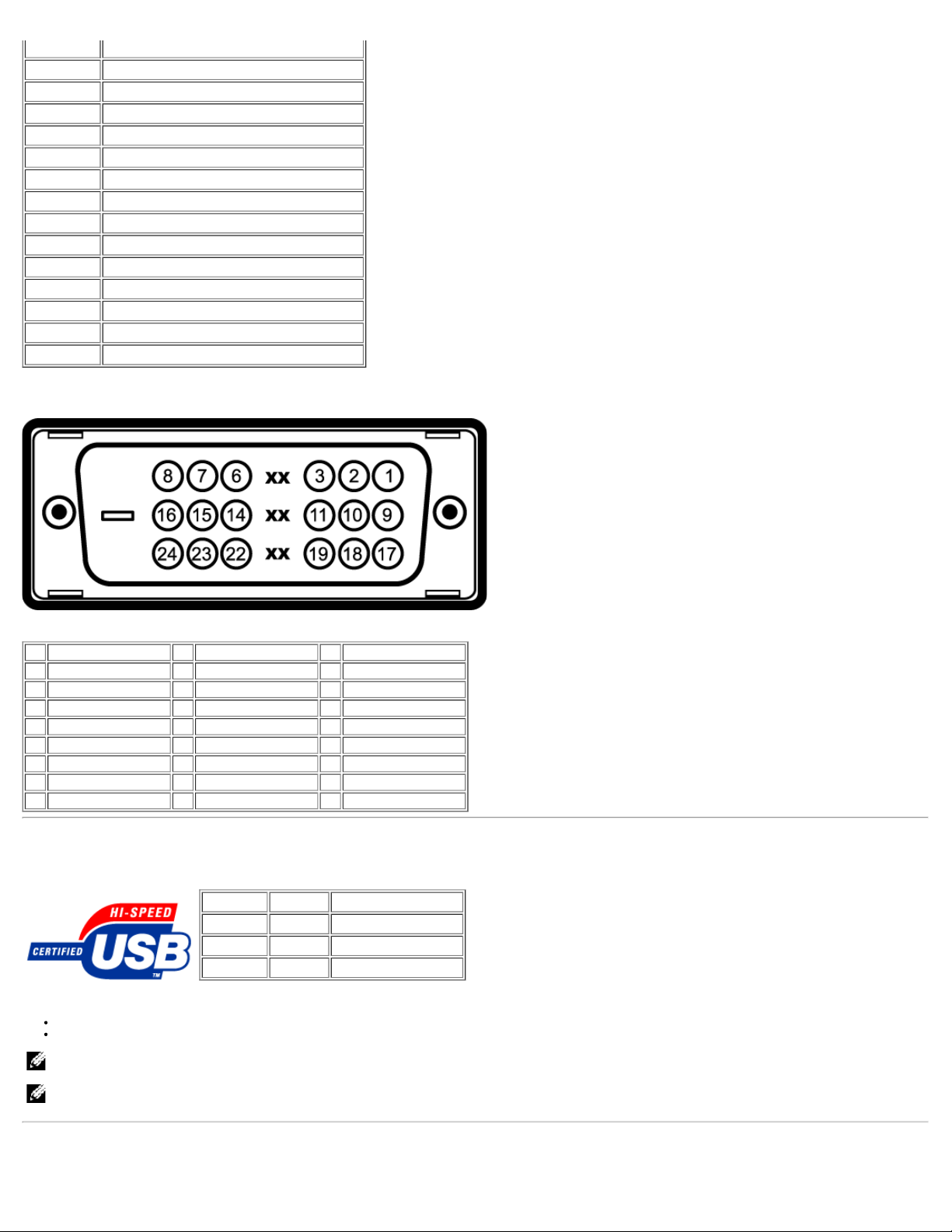
24 pin digital-only DVI connector:
Note: Pin 1 is at the top right.
Pin Signal Assignment Pin Signal Assignment Pin Signal Assignment
1 T.M.D.S. Data 2- 9 T.M.D.S. Data 1- 17 T.M.D.S. Data 02 T.M.D.S. Data 2+ 10 T.M.D.S. Data 1+ 18 T.M.D.S. Data 0+
3 T.M.D.S. Data 2 Shield 11 T.M.D.S. Data 1 Shield 19 T.M.D.S. Data 0 Shield
4 No Pin 12 No Pin 20 No Pin
5 No Pin 13 No Pin 21 No Pin
6 DDC Clock 14 +5V Power 22 T.M.D.S. Clock Shield
7 DDC Data 15 Ground (for +5V) 23 T.M.D.S. Clock +
8 No Connect 16 Hot Plug Detect 24 T.M.D.S. Clock -
Universal Serial Bus (USB) Interface
This monitor supports High-Speed Certified USB 2.0 interface.*
Data Rate Power Consumption
High speed 480 Mbps 2.5W (Max., each port)
Full speed 12 Mbps 2.5W (Max., each port)
Low speed 1.5 Mbps 2.5W (Max., each port)
USB ports:
1 upstream - rear
4 downstream - 2 on rear; 2 on left side
NOTE: USB 2.0 capability requires 2.0 capable computer
NOTE: Monitor's USB interface works ONLY when monitor is Powered ON (or in Power Save Mode). Switching your monitor OFF and then ON would reenumerate its USB interface; attached peripherals may take a few seconds to resume normal functionality.
Plug and Play Capability
You can install the monitor in any Plug and Play-compatible system. The monitor automatically provides the computer system with its Extended Display Identification Data
(EDID) using Display Data Channel (DDC) protocols so the system can configure itself and optimize the monitor settings. If desired, the user can select different settings, but in
Synchronization input signals Separate horizontal and vertical synchronizations, polarity-free TTL level, SOG (Composite SYNC
most cases monitor installation is automatic.
General
Model number 1704FPV
Flat Panel
Screen type Active matrix - TFT LCD
Screen dimensions 17 inches (17-inch viewable image size)
Preset display area:
Horizontal 337 mm (13.3 inches)
Vertical 270 mm (10.6 inches)
Pixel pitch 0.264 mm
Viewing angle 178° (vertical) typ, 178° (horizontal) typ
Luminance output 280 CD/m ²(typ)
Contrast ratio 1000 to 1 (typ)
Faceplate coating Antiglare with hard-coating 3H
Backlight CCFL (4) edgelight system
Response Time 25ms typical
Resolution
Horizontal scan range 30 kHz to 81 kHz (automatic)
Vertical scan range 56 Hz to 76 Hz (automatic)
Optimal preset resolution 1280 x 1024 at 60 Hz
Highest preset resolution 1280 x 1024 at 75 Hz
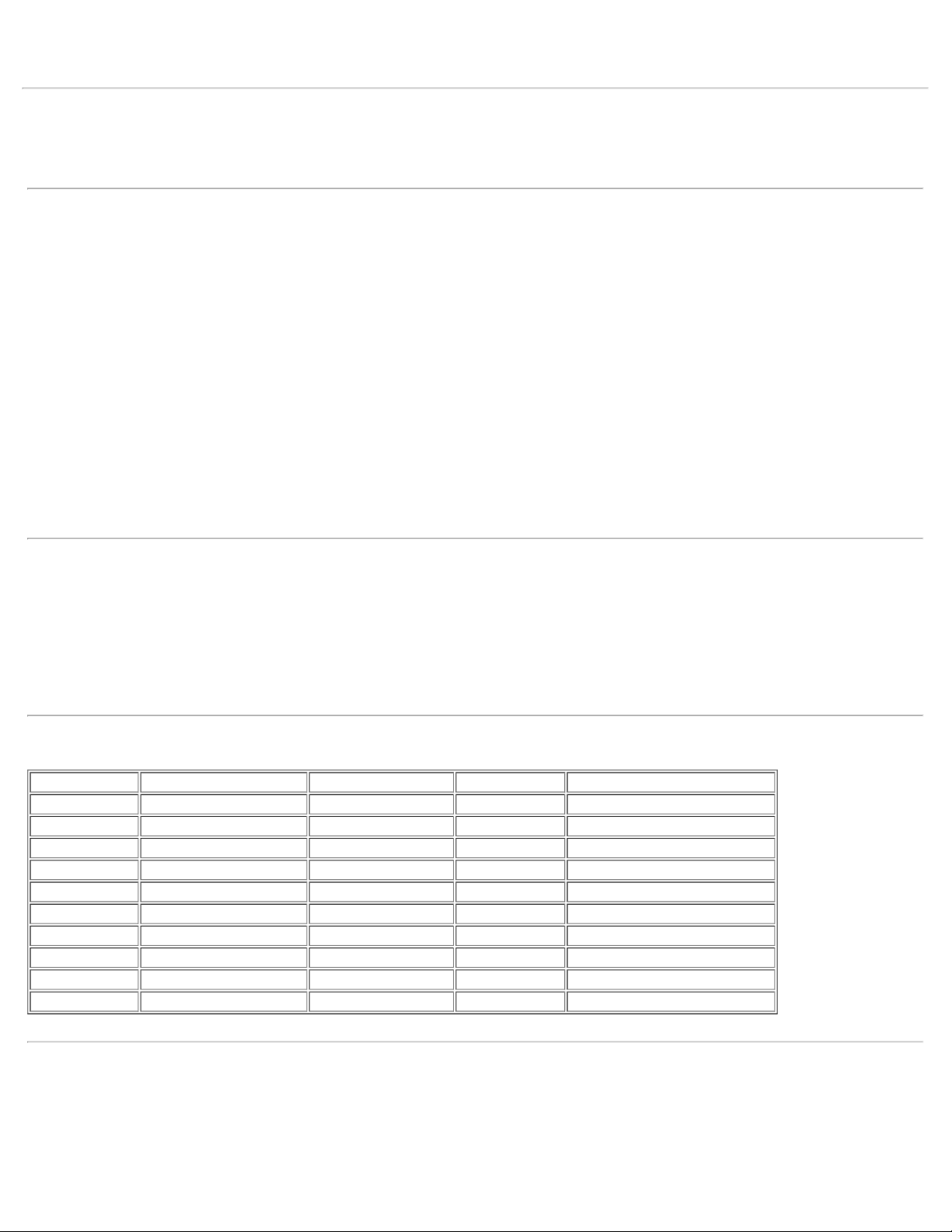
Preset Display Modes
Display Mode Horizontal Frequency (kHz) Vertical Frequency (Hz) Pixel Clock (MHz) Sync Polarity (Horizontal/Vertical)
VESA, 720 x 400 31.5 70.0 28.3 -/+
VESA, 640 x 480 31.5 60.0 25.2 -/VESA, 640 x 480 37.5 75.0 31.5 -/VESA, 800 x 600 37.9 60.3 49.5 +/+
VESA, 800 x 600 46.9 75.0 49.5 +/+
VESA, 1024 x 768 48.4 60.0 65.0 -/VESA, 1024 x 768 60.0 75.0 78.8 +/+
VESA, 1152 x 864 67.5 75.0 108 +/+
VESA, 1280 x 1024 64.0 60.0 135.0 +/+
VESA, 1280 x 1024 80.0 75.0 135.0 +/+
Electrical
Video input signals Analog RGB, 0.7 Volts +/-5%, positive polarity at 75 ohm input impedance
Digital DVI-D TMDS, 600mV for each differential line, positive polarity at 50 ohm input
impedance

on green)
AC input voltage / frequency / current 100 to 240 VAC / 50 or 60 Hz + 3 Hz / 2.0A (Max.)
Inrush current 120V:42A (Max.)
240V:80A (Max.)
Physical Characteristics
Connector type 15-pin D-subminiature, blue connector; DVI-D, white connector
Signal cable type Analog: Detachable, D-sub, 15pin, shipped attached to the monitor
Dimensions (with stand):
Height (fully extended in portrait mode) 548.21 mm (21.58 inches)
Height (compressed/locked in landscape mode) 384.36 mm (15.13 inches)
Width 376 mm (14.8 inches)
Depth 213.79 mm (8.42 inches)
Weight (monitor only) 6.12 Kg (13.48 lb)
Weight (with packaging) 8.3 Kg (18.28 lb)
Digital: Detachable, DVI-D, Solid pins, shipped detached from the monitor
Environmental
Temperature:
Operating 5° to 35°C (41° to 95°F)
Nonoperating Storage: -20° to 60°C (-4° to 140°F)
Humidity:
Operating 10% to 80% (noncondensing)
Nonoperating Storage: 5% to 90% (noncondensing)
Altitude:
Operating 3,657.6m (12,000 ft) max
Nonoperating 12,192 m (40,000 ft) max
Thermal dissipation 221.937 BTU/hour (maximum)
Shipping: -20° to 60°C(-4° to 140°F)
Shipping: 5% to 90%(noncondensing)
109.261 BTU/hour (typical)
Dell Soundbar (Optional) Specifications
System Frequency Response 95 Hz to 20 kHz @ 10 dB below avg. SPL
Total Power Output 14 W continuous average power (all speakers operating) @ 10% (THD+N), 1 kHz (FTC rated)
Headphone Jack
Output Power
Input Sensitivity for
Rated Output
Input Impedance >10kΩ
Maximum Input Signal
Voltage
Controls Power On/Off Volume Control
Input Cables 3.0 m ± 0.1 m AWG26 black cable attached to enclosure, with 3.5 mm lime green stereo plug
Power Requirements DC12V, 1.5A +/-10%
Power Cord Length 305 mm ± 15 mm AWG22 black cable attached to enclosure, with DC plug (5.5 x 2.1 x 12 mm)
Operating Temperature Range 10°C to 40°C
Humidity, Non-condensing 95% RH @ 40 °C
40 mW continuous average power (RL = 32Ω ) @ 10% (THD+N), 1 kHz
500 ± 50 mVrms @ 1 kHz
2 Vrms

Caring for Your Monitor
CAUTION: Read and follow the safety instructions before cleaning the monitor.
CAUTION: Before cleaning the monitor, unplug the monitor from the electrical outlet.
To clean your antistatic screen, lightly dampen a soft, clean cloth with water. If possible, use a special screen-cleaning tissue or solution suitable for the antistatic
coating. Do not use benzene, thinner, ammonia, abrasive cleaners, or compressed air.
Use a lightly-dampened, warm cloth to clean the plastics. Avoid using detergent of any kind as some detergents leave a milky film on the plastics.
If you notice a white powder when you unpack your monitor, wipe it off with a cloth. This white powder occurs during the shipping of the monitor.
Handle your monitor with care as darker-colored plastics may scratch and show white scuff marks more than lighter-colored monitor.
Back to Contents Page
Back to Contents Page
Using Your Adjustable Monitor Stand
Dell™ 1704FPV Flat Panel Monitor
Attaching the Stand
Organizing Your Cables
Using the Tilt, Swivel, and Vertical Extension
Removing the Stand
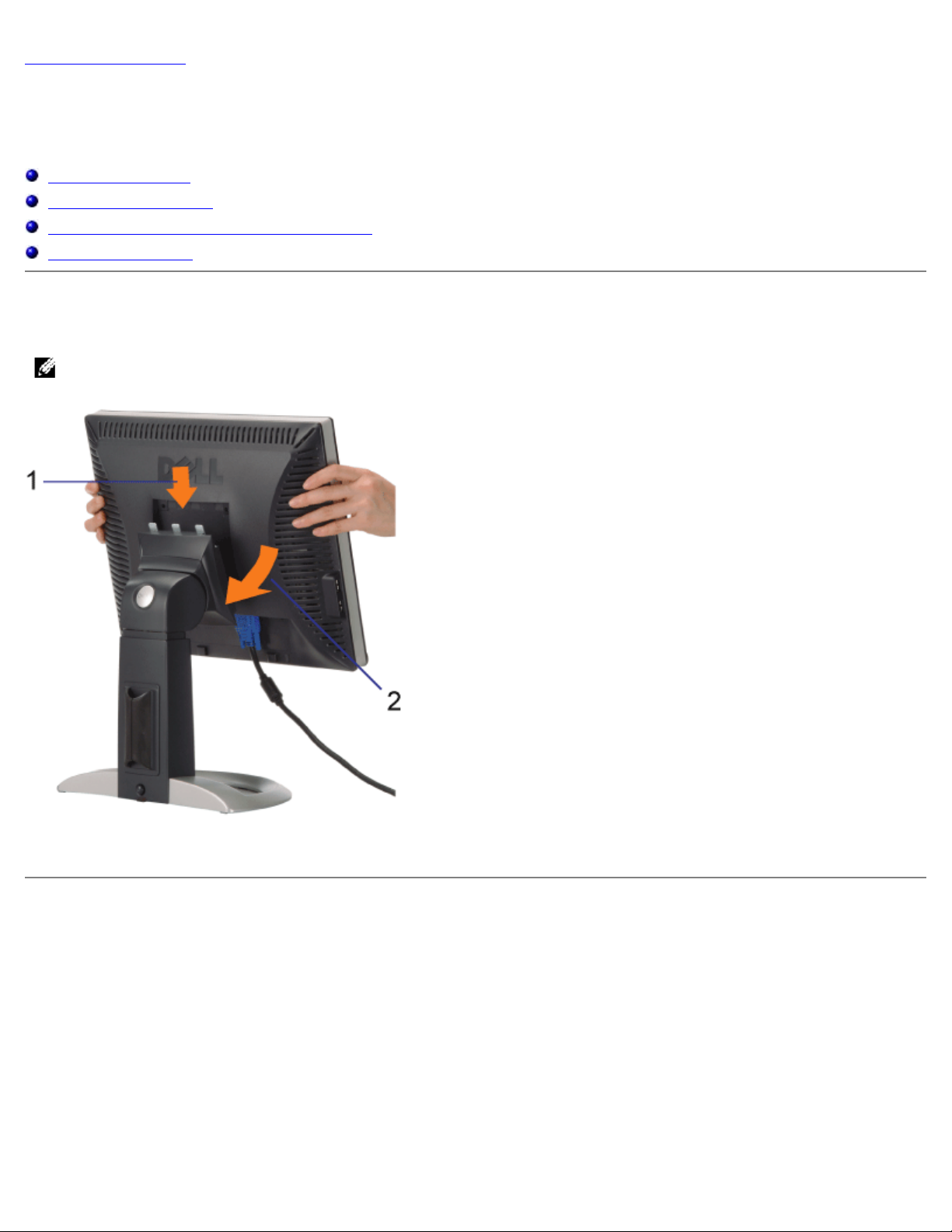
Attaching the Stand
NOTE: The stand is detached and extended when the monitor is shipped from the factory.
1. Fit the groove on the of the monitor onto the three teeth on stand.
2. Lower the monitor until it locks in to place on the stand.
Organizing Your Cables
After attaching all necessary cables to your monitor and computer, (See Connecting Your Monitor for cable attachment,) use
the cable holder to neatly organize all cables as shown above.
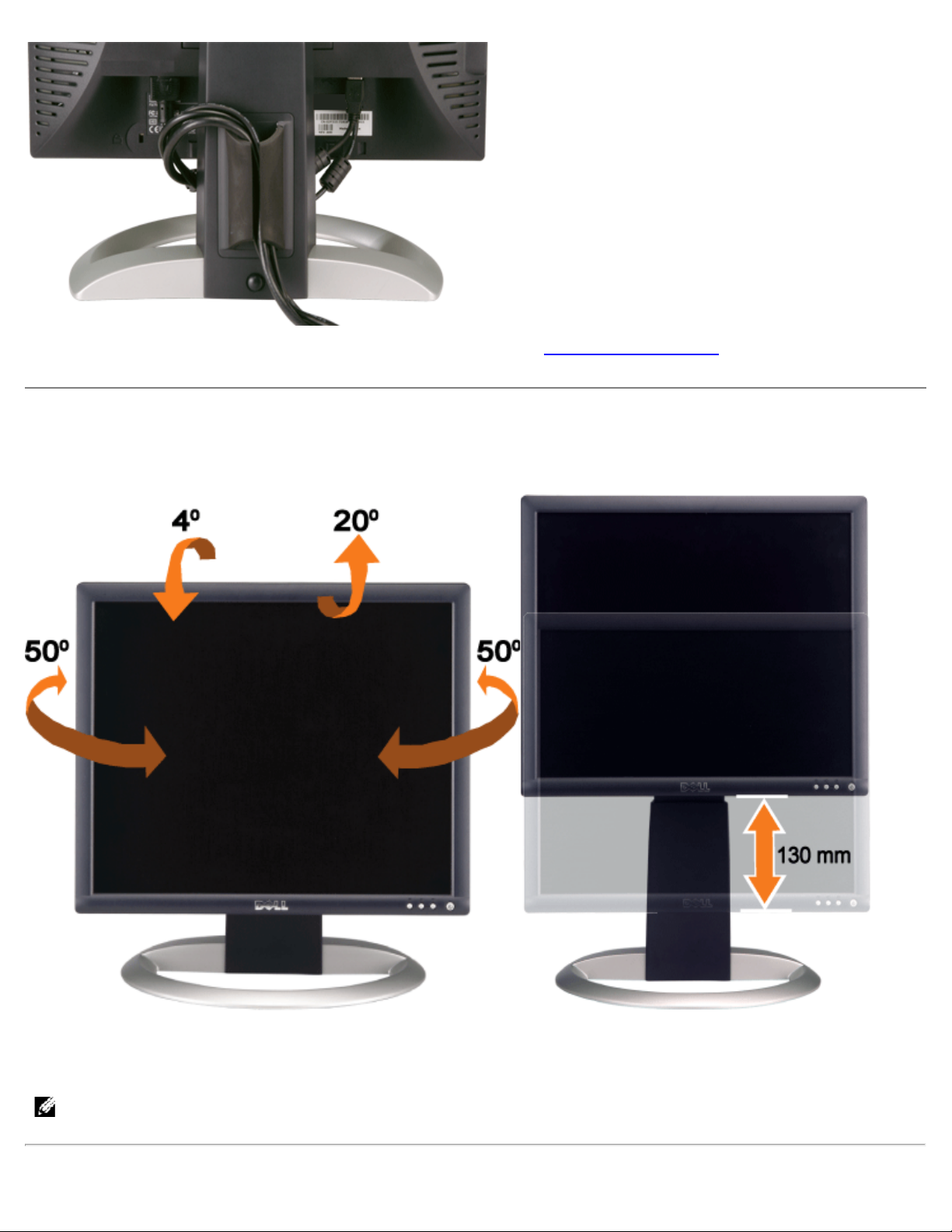
Using the Tilt, Swivel, and Vertical Extension
Adjusting Your Monitor Using Tilt, Swivel, and Vertical Extension. You can adjust your monitor to best fit your viewing needs.
You can adjust the stand vertically, up to 5.12 inches (130mm) using the stand lock/release button. Press the stand
lock/release button on the back of the monitor and then lift or lower the stand to the desired position.
NOTE: Before you move the monitor to a new location, lock the stand by lowering monitor until in clicks in
to place.
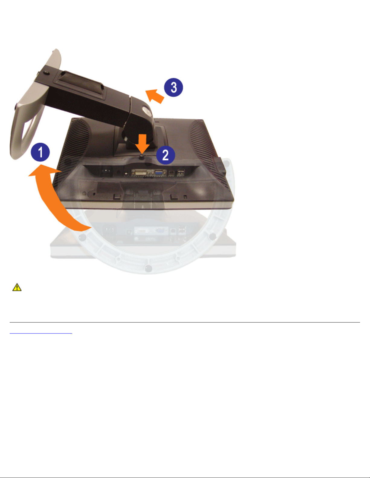
Removing the Stand
NOTICE: After placing the monitor panel on soft cloth or cushion, complete the following steps to remove
the stand.
1. Rotate the stand to allow access to the stand removal button.
2. Press and hold the stand removal button while lifting the monitor up and away from the stand.
Back to Contents Page
Back to Contents Page
Setting Up Your Monitor
Dell™ 1704FPV Flat Panel Monitor
Connecting Your Monitor
Using the Front Panel Buttons
Using the OSD
Setting the Optimal Resolution
Using the Dell Soundbar (Optional)
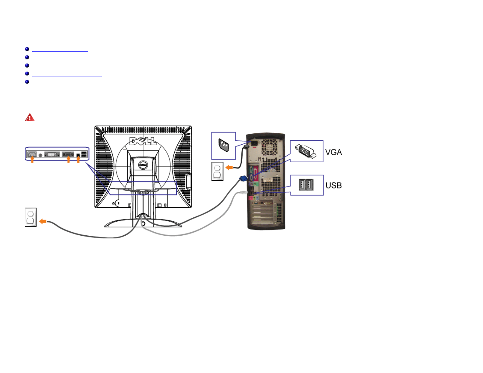
Connecting Your Monitor
CAUTION: Before you begin any of the procedures in this section, follow the safety instructions.
or

1. Turn off your computer and disconnect the power cable.
2. Connect either the white DVI or blue VGA cables to the connectors on the computer and the monitor.
Connect the USB cable that was included with your monitor to the computer and the upstream USB connector on the monitor. Once this cable is connected to the
3.
computer and the monitor, you can use the USB connectors on the monitor.
4. Connect any USB devices.
5. Connect the power cables
Turn on your monitor and computer. If you do not see an image, push the input select button and ensure the correct input source is selected. If you still do not see an
6.
image, see Troubleshooting Your Monitor.
Using the Front Panel Buttons
Use the buttons on the front of the monitor to adjust the image settings.
The Menu button is used to open the on-screen display (OSD), exit from menus and sub-menus, and to exit the OSD. See Using the OSD
OSD menu / select
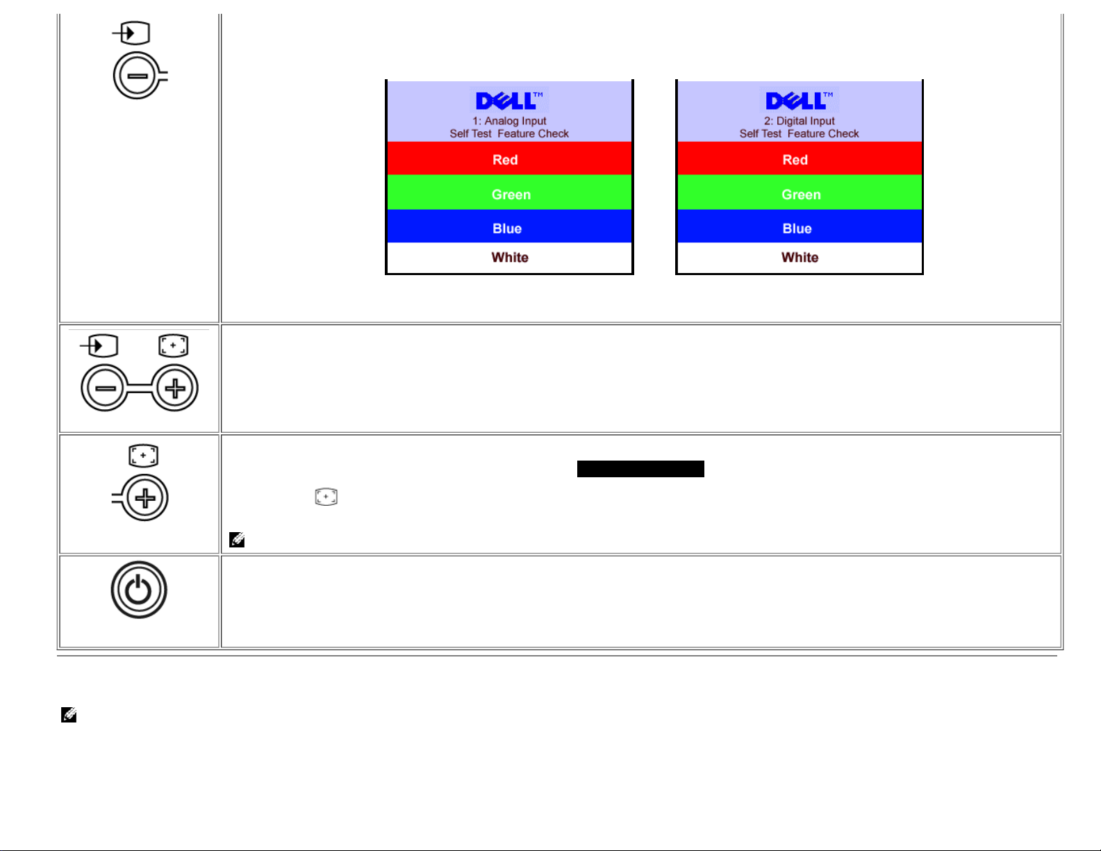
Use the Input Select button to select between two different video signals that may be connected to your monitor.
NOTE: The floating 'Dell - self-test Feature Check' dialog appears (against a black background) if the monitor cannot sense a video
signal. Depending upon the selected input, one of the dialogs shown below will scroll continually.
Input select
Down (-) and Up (+)
or
Use these buttons to adjust (decrease/increase ranges) items in the OSD.
Use this button to activate automatic setup and adjustment. The following dialog appears on a black screen as the monitor self-adjusts to the current input:
Auto Adjust In Progress
button allows the monitor to self-adjust to the incoming video signal. After using Auto Adjustment, you can further tune your monitor by
Auto Adjust
Power Button and
Indicator
Auto Adjustment
using the Pixel Clock (Coarse), Phase (Fine) controls in the OSD.
NOTE: Auto Adjust does not occur if you press the button while there are no active video input signals or attached cables.
Use the power button to turn the monitor on and off.
The green light indicates the monitor is on and fully functional. An amber light indicates power save mode.
Using the OSD
NOTE: If you make an adjustment and then either proceed to another menu, or exit the OSD, the monitor automatically saves any adjustments you have made. If
you make an adjustment and then wait for the OSD to disappear the adjustment are saved.
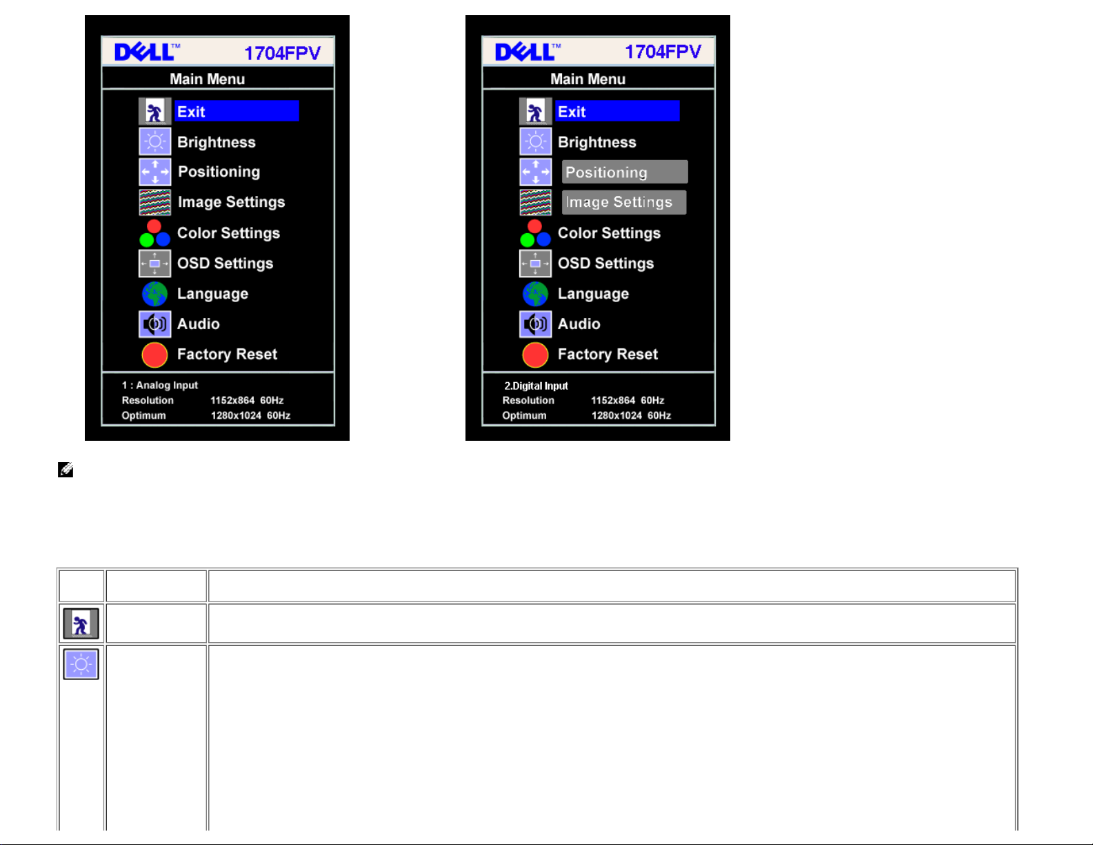
1. Push the MENU button to open the OSD system and display the main menu.
Main Menu for Analog (VGA) Input Main Menu for Digital (DVI) Input
or
NOTE: Positioning and Image settings are only available when you are using the Analog (VGA) connector.
2. Push the - and + buttons to move between the setting options. As you move from one icon to another, the option name is highlighted. See the table below for a complete list of all the
options available for the monitor.
3. Push the MENU button once to activate the highlighted option.
4. Push - and + button to select the desired parameter.
5. Push menu to enter the slide bar and then use the - and + buttons, according to the indicators on the menu, to make your changes.
6. Push the Menu button once to return to the main menu to select another option or push the Menu button two or three times to exit from the OSD.
Icon Menu and
Submenus
Exit Select to exit the Main menu
Brightness/
Contrast
Description
Brightness adjusts the luminance of the backlight.
Adjust Brightness first, then adjust Contrast only if further adjustment is necessary.
Push the + button to increase luminance and push the - button to decrease luminance (min 0 ~ max 100).
Contrast adjusts the degree of difference between darkness and lightness on the monitor screen.
Push the + button to increase the contrast and push the - button to decrease the contrast (min 0 ~ max 100).
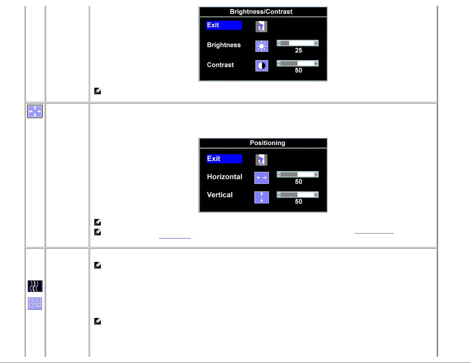
NOTE: When using DVI source, the contrast adjustment is not available
Positioning:
Horizontal
Vertical
Image settings:
Auto Adjust
Pixel Clock
(Coarse)
Phase (Fine)
Positioning moves the viewing area around on the monitor screen.
When making changes to either the Horizontal or Vertical settings, no changes occur to the size of the viewing area, the image shifts in response to your
selection.
Minimum is 0 (-) and maximum is 100 (+).
NOTE: When using DVI source, the Positioning option is not available
NOTE: Horizontal and Vertical OSD positioning adjusts with respect to landscape (default) or portrait display rotation when used in
conjunction with the OSD rotation
feature.
Even though your computer recognizes your monitor on startup, the Auto Adjustment function optimizes the display settings for use with your particular
setup.
NOTE: In most cases, Auto Adjust produces the best image for your configuration.
The Phase and Pixel Clock adjustments allow you to more closely adjust your monitor to your preference. These settings are accessed through the main
OSD menu, by selecting Image Settings.
Use the - and + buttons to make adjustments. (Minimum: 0 ~ Maximum: 100)
If satisfactory results are not obtained using the Phase adjustment, use the Pixel Clock (course) adjustment and then use Phase (fine), again.
NOTE: This function may change the width of the display image. Use the Horizontal function of the Position menu to center the
display image on the screen.
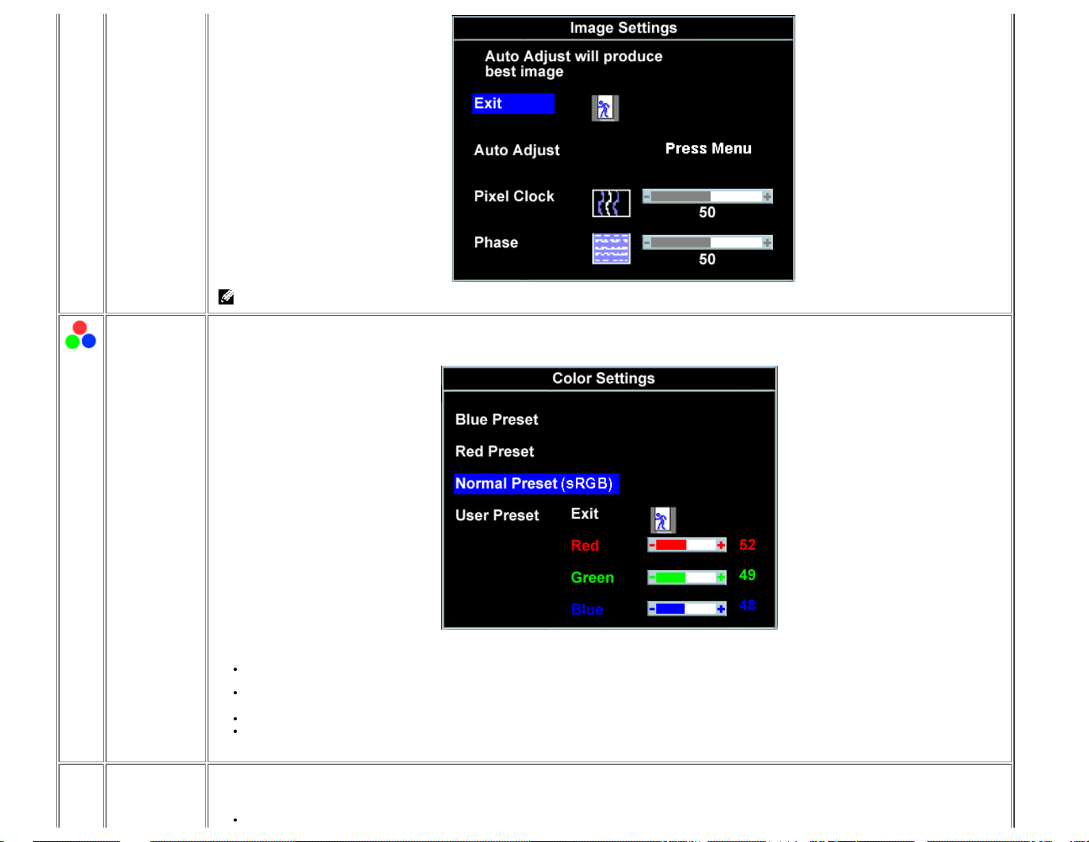
Position
NOTE: When using DVI source, the Image Settings option is not available.
Color Settings
Blue Preset
Red Preset
Normal Preset
User Preset
Color Settings adjusts the color temperature, color hue, and saturation.
The color hue is most noticeable in areas of white.
Blue Preset is selected to obtain a bluish tint. This color setting is typically used for text based applications (spreadsheets, programming, text editors
etc.).
Red Preset is selected to obtain a redder tint. This color setting is typically used for color intensive applications (photograph image editing,
multimedia, movies etc.).
Normal Preset is selected to obtain the default (factory) color settings. This setting is also the “sRGB” standard default color space.
User Preset: Use the plus and minus buttons to increase or decrease each of the three colors (R, G, B) independently, in single digit increments,
from 0 to 100.
OSD Settings:
Horizontal
Adjust the settings for the OSD, including the location, the amount of time the menu remains on-screen, and the rotation of the OSD.
Position of the OSD:
To adjust the horizontal position of the OSD, use the - and + buttons move OSD to the left and right.
 Loading...