

Page 1

Concepts Serving Systems
CAUTION
Use & Care Manual
Please read this manual completely before attempting to install or operate this equipment!
Notify carrier of damage! Inspect all components immediately. See page 2.
IMPORTANT INFORMATION
READ BEFORE USE
PLEASE SAVE THESE INSTRUCTIONS!
Effective June 2010
Page 2
Concepts Use & Care Manual
Important Warning And Safety Information
WARNING Read This Manual Thoroughly Before Operating, Installing, Or Performing
Maintenance On The Equipment.
WARNING Failure To Follow Instructions In This Manual Can Cause Property Damage,
Injury Or Death.
WARNING Do Not Store Or Use Gasoline Or Other Flammable Vapors Or Liquids In The
Vicinity Of This Or Any Other Appliance.
WARNING Unless All Cover And Access Panels Are In Place And Properly Secured, Do
Not Operate This Equipment.
WARNING Do Not Clean With Water Jet.
CAUTION Observe the following:
Minimum clearances must be maintained from all walls and combustible
•
materials.
Keep the equipment area free and clear of combustible material.
•
Adequate clearance for air openings.
•
Operate equipment only on the type of electricity indicated on the
•
specification plate.
Retain this manual for future reference.
•
2
For customer service, call (800) 733-8829, (800) 773-8821, Fax (989) 773-3210, www.delfield.com
Page 3

Concepts Use & Care Manual
Contents Serial Number Information
Receiving & Inspecting The Equipment ....................................4
Specifications ..........................................................................5-7
If your unit is heated, the serial tag is located above the louvered
panel near the on/off switch.
Installation
Heated Units ...........................................................................8
Refrigerated Units ...................................................................8
Operation
Heated Units ............................................................................9
Mechanically Cooled Serving Counters ..................................9
LiquiTec Units .......................................................................10
Frost Top Serving Counters ..................................................10
Maintenance .............................................................................11
Wiring Diagrams
Heated Serving Counter ........................................................12
Mechanically Cooled Serving Counter ..................................13
LiquiTec Units .......................................................................13
Refrigerated units have the serial tag located in the compressor
area near the on/off switch.
Understorage units often have the serial tag located on the left
inside the storage area.
All purpose counters, utility equipment or delivery carts do
not require serial numbers but a model tag is placed at the top
of the pylon on the back of the unit.
Always have the serial number of your unit available when
calling for parts or service.
This manual covers standard units only. If you have a custom
unit, consult the customer service department at the number
listed below.
Frost Top Serving Counters ..................................................13
Standard Labor Guidelines ......................................................14
Replacement Parts List ............................................................15
Standard Warranty ..............................................................16-17
Notes ...................................................................................18-19
©2010 The Delfield Company. All rights reserved. Reproduction without written permission is prohibited.
“Delfield” is a registered trademarks of The Delfield Company.
For customer service, call (800) 733-8829, (800) 773-8821, Fax (989) 773-3210, www.delfield.com
3
Page 4
Concepts Use & Care Manual
Receiving And Inspecting The Equipment
Even though most equipment is shipped crated, care should
be taken during unloading so the equipment is not damaged
while being moved into the building.
1.
Visually inspect the exterior of the package and skid or
container. Any damage should be noted and reported to
the delivering carrier immediately.
2.
If damaged, open and inspect the contents with the
carrier.
3.
In the event that the exterior is not damaged, yet upon
opening, there is concealed damage to the equipment
notify the carrier. Notification should be made verbally
as well as in written form.
4.
Request an inspection by the shipping company of the
damaged equipment. This should be done within 10
days from receipt of the equipment.
5.
Check the lower portion of the unit to be sure legs or
casters are not bent.
6.
Also open the compressor compartment housing and
visually inspect the refrigeration package. Be sure lines
are secure and base is still intact.
7.
Freight carriers can supply the necessary damage forms
upon request.
8.
Retain all crating material until an inspection has been
made or waived.
Uncrating the Equipment
First cut and remove the banding from around the crate.
Remove the front of the crate material, use of some tools will
be required. If the unit is on legs remove the top of the crate
as well and lift the unit off the skid. If the unit is on casters it
can be "rolled" off the skid.
The units with LiquiTec technology cold pans contain
a non-toxic eutectic fluid within a sealed inner liner.
This fluid may leak if the tank is punctured so care
must be taken when uncrating and setting in place.
The eutectic fluid is non-toxic and may be flushed
down a disposal drain. If the LiquiTec unit cold pans
leak, immediately call the Delfield service department
directly at 1-800-733-8821 not your local service
agent.
4
For customer service, call (800) 733-8829, (800) 773-8821, Fax (989) 773-3210, www.delfield.com
Page 5
Concepts Use & Care Manual
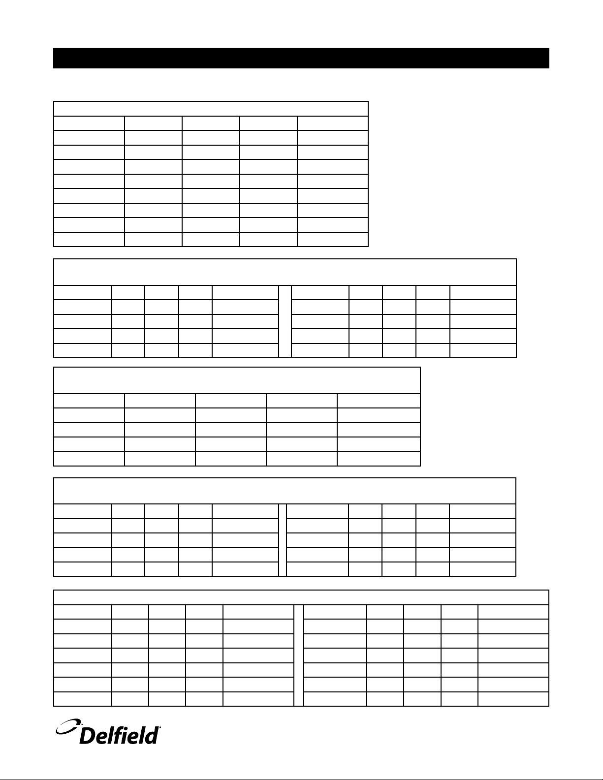
Specifications
This manual covers standard units only. If you have a custom unit, consult the customer service department at the number listed below.
Cashier Counter
Model Length Width Height Ship Weight
DCCS-SD 45.00” 36.00” 36.00” 270lbs/122kg
DCCS-SDW 45.00” 54.00” 36.00” 320lbs/145kg
DCCS-SDWL 45.00” 54.00” 36.00” 295lbs/134kg
DCCS-SDWR 45.00” 54.00” 36.00” 295lbs/134kg
DCCS-DD 72.00” 36.00” 36.00” 540lbs/245kg
DCCS-DDW 72.00” 54.00” 36.00” 590lbs/268kg
DCCS-DDWL 72.00” 54.00” 36.00” 565lbs/256kg
DCCS-DDWR 72.00” 54.00” 36.00” 565lbs/256kg
Flexi Shield™ Food Shields
Radial Glass Fro nt, Single Tier with Glass Shelf, Single Serv ice, Inside & Outside
Model L W H Ship Weight Model L W H Ship Weight
DCFSRIG-2 38.47” 18.00” 18.00” Contact Factor y DCFSROG-2 43.09” 18.00” 18.00” Contact Factor y
DCFSRIG-3 53.43” 18.00” 18.00” Contact Factor y DCFSROG-3 59.85” 18.00” 18.00” Contact Factor y
DCFSRIG-4 68.17” 18.00” 18.00” Contact Factor y DCFSROG-4 76.35” 18.00” 18.00” Contact Factor y
DCFSRIG-5 82.61” 18.00” 18.00” Contact Factor y DCFSROG-5 92.53” 18.00” 18.00” Contact Factor y
Flexi Shield™ Food Shields
Radial Single Tier, Fixed S neeze Guard Front, Dual Ser vi ce
Model L W H Ship Weight
DCFSRKD-2 40.78” 35.50” 14.75” Contact Factor y
DCFSRKD-3 56.64” 35.50” 14.75” Contact Factor y
DCFSRKD-4 72.26” 35.50” 14.75” Contact Factor y
DCFSRKD-5 87.57” 35.50” 14.75” Contact Factor y
Flexi Shield™ Food Shields
Radial Single Tier, Fixed S neeze Guard Front, Sing le Ser vice, Inside & Outside
Model L W H Ship Weight Model L W H Ship Weight
DCFSRIKS-2 38.47” 18.00” 14.75” Contact Factory DCFSROKS-2 43.09” 18.00” 14.75” Contact Factor y
DCFSRIKS-3 53.43” 18.00” 14.75” Contact Factory DCFSROKS-3 59.85” 18.00” 14.75” Contact Factor y
DCFSRIKS-4 68.17” 18.00” 14.75” Contact Factory DCFSROKS-4 76.35” 18.00” 14.75” Contact Factor y
DCFSRIKS-5 82.61” 18.00” 14.75” Contact Factory DCFSROKS-5 92.53” 18.00” 14.75” Contact Factor y
Specifications
Model Length Depth Height Ship Weight Model Length Depth Height Ship Weight
DCBU-38 38.00” 36.00” 36.00” 171lbs/78kg DCBU-T38 38.00” 36.00” 36.00” 171lbs/78kg
DCBU-52 52.00” 36.00” 36.00” 234lbs/106kg DCBU-T52 52.00” 36.00” 36.00” 234lbs/106kg
DCBU-66 66.00” 36.00” 36.00” 297lbs/135kg DCBU-T66 66.00” 36.00” 36.00” 297lbs/135kg
DCBU-80 80.00” 36.00” 36.00” 360lbs/163kg DCBU-T80 80.00” 36.00” 36.00” 360lbs/163kg
DCBU-94 94.00” 36.00” 36.00” 423lbs/192kg DCBU-T94 94.00” 36.00” 36.00” 423lbs/192kg
DCBU-120 120.00” 36.00” 36.00” 540lbs/245kg DCBU-T120 120.00” 36.00” 36.00” 540lbs/245kg
For customer service, call (800) 733-8829, (800) 773-8821, Fax (989) 773-3210, www.delfield.com
5
Page 6
Concepts Use & Care Manual
Specifications, continued
Self-Contained Frost Top Serving Counter
Model Length Depth Height H.P. V/Hz/Ph Amps Ship Weight
DC-FT2 38.00” 36.00” 36.00” 1/4 115/60/1 7.5 399lbs/181kg
DC-FT3 52.00” 36.00” 36.00” 1/4 115/60/1 7.5 546lbs/248kg
DC-FT4 66.00” 36.00” 36.00” 1/4 115/60/1 7.5 693lbs/314kg
DC-FT5 80.00” 36.00” 36.00” 1/4 115/60/1 7.5 840lbs/381kg
DC-FT6 94.00” 36.00” 36.00” 1/3 115/60/1 8.0 987lbs/448kg
Heated Serving Counter
Model Length Depth Height Watts
DC-H2 38.00” 36.00” 36.00” 2000 2 115/60/1 16.6 228lbs/103kg
DC-H3 52.00” 36.00” 36.00” 3000/4000 3 208230/60/1 15.0/16.0 312lbs/142kg
DC-H4 66.00” 36.00” 36.00” 4000/4800 4 208230/60/1 20.0/22.0 396lbs/180kg
DC-H5 80.00” 36.00” 36.00” 5000/6000 5 208230/60/1 24.0/27.0 480lbs/218kg
DC-H6 94.00” 36.00” 36.00” 6000/7200 6 208230/60/1 29.0/32.0 564lbs/256kg
# of 12x20
Pans Held
V/Hz/Ph Amps Ship Weight
Ice Cooled Serving Counter
Model Length Depth Height
DC-IC2 38.00” 36.00” 36.00” 2 209lbs/95kg
DC-IC3 52.00” 36.00” 36.00” 3 286lbs/130kg
DC-IC4 66.00” 36.00” 36.00” 4 363lbs/165kg
DC-IC5 80.00” 36.00” 36.00” 5 440lbs/200kg
DC-IC6 94.00” 36.00” 36.00” 6 517lbs/235kg
Self-Contained LiquiTec® Cold Pan Serving Counter
Model Length Depth Height
DC-L2 38.00” 36.00” 36.00” 2 1/4 115/60/1 7.5 379 342lbs/155kg
DC-L3 52.00” 36.00” 36.00” 3 1/4 115/60/1 7.5 569 468lbs/212kg
DC-L4 66.00” 36.00” 36.00” 4 1/4 115/60/1 7.5 758 594lbs/269kg
DC-L5 80.00” 36.00” 36.00” 5 1/4 115/60/1 7.5 948 720lbs/327kg
DC-L6 94.00” 36.00” 36.00” 6 1/4 115/60/1 7.5 1138 846lbs/384kg
Self-Contained Mechanically Cooled Serving Counter
Model Length Depth Height
DC-MC2 38.00” 36.00” 36.00” 2 1/4 115/60/1 7.5 379 323lbs/147kg
DC-MC3 52.00” 36.00” 36.00” 3 1/4 115/60/1 7.5 569 442lbs/200kg
DC-MC4 66.00” 36.00” 36.00” 4 1/4 115/60/1 7.5 758 561lbs/254kg
DC-MC5 80.00” 36.00” 36.00” 5 1/4 115/60/1 7.5 948 680lbs/308kg
DC-MC6 94.00” 36.00” 36.00” 6 1/3 115/60/1 8.0 1138 799lbs/362kg
# of 12x20
Pans Held
# of 12x20
Pans Held
# of 12x20
Pans Held
H.P. V/Hz/Ph Amps BTU Ship Weight
H.P. V/Hz/Ph Amps BTU Load Ship Weight
Ship Weight
6
For customer service, call (800) 733-8829, (800) 773-8821, Fax (989) 773-3210, www.delfield.com
Page 7

Concepts Use & Care Manual
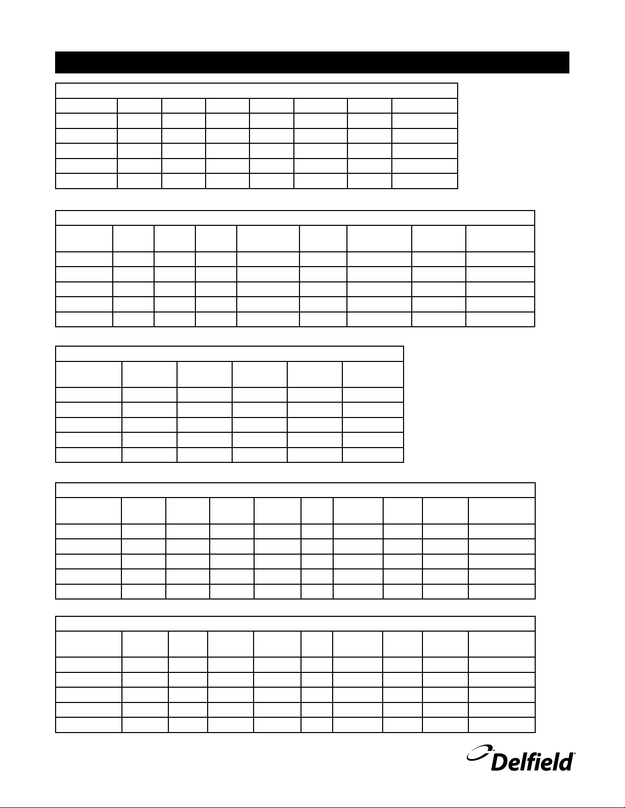
Specifications, continued
Radial Utility Serving Counter
Model Length Depth Height Ship Weight
DCRU-O 103.32” 36.00” 36.00” 464lbs/210kg
DCRU-I 103.32” 36.00” 36.00” 464lbs/210kg
DCRU-OT 103.32” 36.00” 36.00” 464lbs/210kg
DCRU-IT 103.32” 36.00” 36.00” 464lbs/210kg
Radial Heated Serving Counter
Model Length Depth Height Watts
DCRU-H2 103.32” 36.00” 36.00” 2000 2 115/60/1 16.6 563lbs/255kg
DCRU-H3 103.32” 36.00” 36.00” 3000/4000 3 208230/60/1 15.0/16.0 604lbs/274kg
DCRU-H4 103.32” 36.00” 36.00” 4000/4800 4 208230/60/1 20.0/22.0 645lbs/293kg
DCRU-H5 103.32” 36.00” 36.00” 5000/6000 5 208230/60/1 24.0/27.0 685lbs/311kg
Radial Ice Cooled Serving Counter
Model Length Depth Height
DCRU-IC2 103.32” 36.00” 36.00” 2 540lbs/245kg
DCRU-IC3 103.32” 36.00” 36.00” 3 578lbs/262kg
DCRU-IC4 103.32” 36.00” 36.00” 4 616lbs/279kg
DCRU-IC5 103.32” 36.00” 36.00” 5 654lbs/297kg
# of 12x20
Pans Held
# of 12x20
Pans Held
V/Hz/Ph Amps Ship Weight
Ship Weight
Radial Self-Contained LiquiTec® Cold Pan Serving Counter
Model Length Depth Height
DCRU-L1 103.32” 36.00” 36.00” 1 1/4 115/60/1 7.5 292 633lbs/287kg
DCRU-L2 103.32” 36.00” 36.00” 2 1/4 115/60/1 7.5 379 679lbs/308kg
DCRU-L3 103.32” 36.00” 36.00” 3 1/4, 1/4 115/60/1 7.5/7.5 292/379 848lbs/385kg
DCRU-L4 103.32” 36.00” 36.00” 4 1/4, 1/4 115/60/1 7.5/7.5 379/379 894lbs/406kg
Radial Self-Contained Mechanically Cooled Serving Counter
Model Length Depth Height
DCRU-MC2 103.32” 36.00” 36.00” 2 1/4 115/60/1 7.5 379 604lbs/274kg
DCRU-MC3 103.32” 36.00” 36.00” 3 1/4 115/60/1 7.5 569 644lbs/292kg
DCRU-MC4 103.32” 36.00” 36.00” 4 1/4 115/60/1 7.5 758 684lbs/310kg
DCRU-MC5 103.32” 36.00” 36.00” 5 1/4 115/60/1 7.5 948 724lbs/328kg
Transition Counters
Model Length Depth Height Ship Weight
DC-T22 25.81” 36.00” 36.00” 86lbs/39kg
DC-T45 38.64” 36.00” 36.00” 171lbs/78kg
DC-T90 59.40” 36.00” 36.00” 315lbs/143kg
DC-TT45 38.64” 36.00” 36.00” 171lbs/78kg
DC-TT90 59.40” 36.00” 36.00” 315lbs/143kg
DCRU-T22 18.92” 36.00” 36.00” 86lbs/39kg
DCRU-T45 37.12” 36.00” 36.00” 171lbs/78kg
DCRU-T90 68.59” 36.00” 36.00” 315lbs/143kg
DCRU-TT 45 37.12” 36.00” 36.00” 171lbs/78kg
DCRU-TT 90 68.59” 36.00” 36.00” 315lbs/143kg
# of 12x20
Pans Held
# of 12x20
Pans Held
H.P. V/Hz/Ph Amps BTU Ship Weight
H.P. V/Hz/Ph Amps BTU Load Ship Weight
For customer service, call (800) 733-8829, (800) 773-8821, Fax (989) 773-3210, www.delfield.com
7
Page 8

Concepts Use & Care Manual
CAUTION
Installation: Heated Units
Location
Do not install the unit near combustible objects or surfaces
affected by heat or moisture.
Leveling
The unit must be level, both front and back and left to right,
in order to maintain an equal water depth throughout the
wells.
Electrical Connections
Connections must be made in accordance with all
applicable local codes and/or the National Electrical
Code. Refer to the amperage data on page 3 and the
wiring diagrams on pages 8 and 9. A standard unit
is provided with a power cord and 3-prong grounded
Installation: Refrigerated Units
Location
Be sure the location chosen has a floor strong enough to support
the total weight of the cabinet and contents. Reinforce the floor
as necessary to provide for maximum loading.
For the most efficient refrigeration, be sure to provide good air
circulation inside and out.
Inside cabinet: Do not pack unit so full that air cannot
circulate. Take care not to block air flow to the fans and allow
space along the sides.
Outside cabinet: Be sure the unit has access to ample air;
avoid hot corners and locations near stoves and ovens. It
is suggested the rear of the unit be no less than two inches
from any wall, partition or any other object which will restrict
exhaust air flow.
Leveling
A level cabinet looks better and will perform better because
the doors will line up with the door frames properly, and the
cabinet will not be subject to unnecessary strain.
Stabilizing
Some models are supplied on casters for your convenience,
for ease of cleaning underneath and mobility.
The unit must be installed in a stable condition with
the front wheels locked, locking the front casters
after installation is the owner’s and operator’s
responsibility.
Plumbing
Refrigerated units have a drain that exits the unit on the bottom,
and is located on the operator’s left side. Standard units on
casters or legs will have a bronze faucet that fits a standard
garden hose. Units on legs with optional remote drain valve
plug. All units should be plugged into a grounded
receptacle with its own circuit protection that matches the amperage of the plug.
Before the unit is used the first time for serving:
Turn the temperature knob to “10” and heat the well for 15
•
minutes. Do not be alarmed if smoke appears; this preheat
should burn off any residue or dust that has adhered to the
food well element
handle will have 1” threaded pipe extending from bottom of unit.
On standard units, a stainless steel access panel or hinged louver
will be provided for access to drain connections.
Moisture collecting from improper drainage can
create a slippery surface on the floor and a hazard
to employees. It is the owner’s and operator’s
responsibility to provide a container or outlet for
drainage.
Electrical connection
A standard refrigerated unit is provided with a power cord and
3-prong grounded plug.
The unit should be plugged into a receptacle with its own
circuit protection that matches the amperage of the plug.
Refer to the amperage data on page 3 or the
serial tag data and your local code or the National
Electrical Code to be sure the unit is connected
to the proper power source. A protected circuit
of the correct voltage and amperage must be run
for connection of the supply cord or permanent
connection to the unit.
On cord-connected units, an ON/OFF switch is
located directly on the face of the compressor
section. The switch must be turned to its OFF
position and power supply disconnected whenever
doing the following:
Performing maintenance functions.
1.
Cleaning the refrigerated cabinet area.
2.
Performing service or repair functions.
3.
Under no circumstances should the unit be operated without
the louvered panel in place.
8
For customer service, call (800) 733-8829, (800) 773-8821, Fax (989) 773-3210, www.delfield.com
Page 9

Operation: Heated Units
Concepts Use & Care Manual
After plugging in the power supply cord, select desired
temperature by rotating the knob on the temperature control
panel. Indicator light will come on when the switch is activated.
Individual temperature control knobs and indicator lights are
provided for each heated food well.
If the same temperature settings for each well are used every
day, the temperature knobs can be left in their set position and
the wells can be turned off using the ON/OFF switch at the end
of the control panel.
When serving thick sauces always use the hot food well in
“wet” operation. This provides more uniform temperature for
the sauce. Product temperature should range from 140˚F to
160˚F
Never place food directly in well. Always use
pans.
For most efficient operation, keep covered insets empty in each
well during preheating and when the well is not in use.
Always place covers on pans when not serving to prevent food
from drying out and to reduce your operating costs.
Wet operation
Fill the food well with about two inches of hot water and cover
with lid or empty pan. To bring water to highest temperature,
set temperature control at “High”. With pans in place, wells
will boil water. Food temperature will vary depending on type
and amount of product. To minimize steam and water usage,
set control to lowest setting that will maintain proper food
temperature.
Steam can cause serious burns. Always wear
some type of protective covering on your hands
and arms when removing lids from the unit. Lift
the lid in a way that will direct escaping steam
away from your face and body. Water temperature
will average 180˚F.
Dry operation
Wet operation is usually much more efficient and is usually
preferred. However, these units may be operated without water
with no damage to the unit.
The dry well should never be preheated longer
than 15 minutes. Only 6” deep pans should be
used with dry food wells.
When operated dry, the well bottoms become very
hot. Do not allow unprotected skin to contact any
well surface.
When operated dry, the bottom of the well will discolor. To
clean, use a stainless steel cleaner or mild abrasive.
Operation of optional heated understorage
If necessary, preheat the heated understorage to desired
temperature. Temperature range of understorage is 80°F to
190°F. The temperature control knob is always the far left knob
on the panel. Indicator light is also at the far left.
Operation: Mechanically Cooled Serving Counters
Mechanically cooled cold pans are adjusted at the factory to
provide proper operation without any further adjustments.
However, if it is necessary to adjust the temperature, the
control is located in the machine compartment. Turn the knob
clockwise as indicated on the control. Settings are from 1 thru
7, 7 being the coldest. Adjustments should be made gradually.
Several small adjustments will be more effective than one
large adjustment. It may take an hour or longer to realize the
temperature change depending on the application and location
of the unit.
Turn the cold pan on an hour or longer before loading product
to achieve the desired temperature.
These units are not designed to cool warm food products. Items
should be placed in the unit pre-cooled at least to the desired
holding temperature, if not slightly colder. In some applications,
a gradual warming of product may occur, particularly at the
exposed top of the product. Stirring or rotation of the product
For customer service, call (800) 733-8829, (800) 773-8821, Fax (989) 773-3210, www.delfield.com
may be necessary to maintain overall temperature.
Warming of food product can occur very quickly outside of
the unit. When loading or rotating product, avoid leaving food
items in a non-refrigerated location for any length of time to
prevent warming or spoilage.
The temperature control is used to turn the unit on and off as
well as control the temperature of the cold pan. The settings
range from 1 through 7, 7 being the coldest. To turn the cold
pan off, turn the knob to the OFF position.
These units are not designed to be used with ice. If the cold
pan is to be used with ice, it is recommended that the optional
perforated bottoms be used. These will allow ice to melt
properly.
The unit must be turned off when not in use or overnight for
defrosting and cleaning.
9
Page 10

Concepts Use & Care Manual
Operation: LiquiTec Units
There is a switch on the compressor housing front to turn the units
on and off. LiquiTec Series cold pans are adjusted at the factory
to provide proper operation without any further adjustments.
However, if it is necessary to adjust the temperature, the control
is located in the machine compartment. Turn the knob clockwise
as indicated on the control to adjust it colder. Adjustments
should be made gradually. Several small adjustments will be
more effective than one large adjustment. It may take an hour
or longer to realize the temperature change depending on the
application and location of the unit.
Turn the cold pan on an hour or longer before loading product
to achieve the desired temperature.
These units are not designed to cool warm food products. Items
should be placed in the unit pre-cooled at least to the desired
holding temperature, if not slightly colder. In some applications,
a gradual warming of product may occur, particularly at the
exposed top of the products. Stirring or rotation of the product
may be necessary to maintain overall temperature. Warming of
food product can occur very quickly outside of the unit. When
loading or rotating the product, avoid leaving food items in
a non-refrigerated location for any length of time to prevent
warming or spoilage.
The cold pan is not intended to be used with ice.
The unit must be turned off when not in use or overnight for
defrosting and cleaning.
Temperature Control Settings:
17°F (8ºC) differential
25°F (-4ºC) cut-in
8°F (-13ºC) cut-out
Operation: Frost Top Serving Counters
Frost tops are designed to maintain an even layer of frost to
pleasantly display product. Once turned on, the compressor
will run continuously. The unit should be turned off overnight
or when not in use. There is no temperature control on the
frost top series. The ON/OFF switch is the only means available
to cycle the unit.
Since it takes time for the frost to accumulate initially, the unit
should be turned on approximately one hour before it is actually
required. Product should not be placed on the frost top prior
to turning the unit on, because it may freeze to the surface of
the unit.
The unit must be turned off when not in use or overnight for
defrosting and cleaning.
10
For customer service, call (800) 733-8829, (800) 773-8821, Fax (989) 773-3210, www.delfield.com
Page 11

Maintenance
Concepts Use & Care Manual
Drain Maintenance - Base
Each unit has a drain located inside the unit that removes
the condensation from the evaporator coil and routes it to an
external condensate evaporator pan. Each drain can become
loose or disconnected during normal use. If you notice water
accumulation on the inside of the unit be sure the drain tube
is connected to the evaporator drain pan. If water is collecting
underneath the unit make sure the end of the drain tube is in
the condensate evaporator in the machine compartment. The
leveling of the unit is important as the units are designed to
drain properly when level. Be sure all drain lines are free of
obstructions.
Caster Maintenance
Wipe casters with a damp cloth monthly to prevent corrosion.
The power switch must be turned to OFF and the
unit disconnected from the power source whenever
performing service, maintenance functions or
cleaning the refrigerated area.
Refrigerators and Freezers
The interior and exterior can be cleaned using soap and warm
water. If this isn’t sufficient, try ammonia and water or a
nonabrasive liquid cleaner. When cleaning the exterior, always
rub with the “grain” of the stainless steel to avoid marring the
finish. Do not use an abrasive cleaner because it will scratch the
stainless steel and can damage the breaker strips and gaskets.
Stainless Steel Care and Cleaning
To prevent discoloration or rust on stainless steel several
important steps need to be taken. First, we need to understand
the properties of stainless steel. Stainless steel contains 70- 80%
iron, which will rust. It also contains 12-30% chromium, which
forms an invisible passive film over the steel’s surface, which
acts as a shield against corrosion. As long as the protective
layer is intact, the metal is still stainless. If the film is broken
or contaminated, outside elements can begin to breakdown the
steel and begin to form discoloration or rust. Proper cleaning of
stainless steel requires soft cloths or plastic scouring pads.
Never use an acid based cleaning solution! Many
food products have an acidic content, which can
deteriorate the finish. Be sure to clean the stainless
steel surfaces of ALL food products. Common items
include, tomatoes, peppers and other vegetables.
Cleaning the Condenser Coil
In order to maintain proper refrigeration performance, the
condenser fins must be cleaned of dust, dirt and grease
regularly. It is recommended that this be done at least every
three months. If conditions are such that the condenser is totally
blocked in three months, the frequency of cleaning should be
increased. Clean the condenser with a vacuum cleaner or stiff
brush. If extremely dirty, a commercially available condenser
cleaner may be required.
Failure to maintain a clean condenser coil can initially cause high
temperatures and excessive run times. Continuous operation
with a dirty or clogged condenser coil can result in compressor
failure. Neglecting the condenser coil cleaning procedures will
void any warranties associated with the compressor and cost
to replace the compressor.
Never use a high-pressure water wash for this
cleaning procedure as water can damage the
electrical components located near or at the
condenser coil.
Preventing blower coil corrosion
To help prevent corrosion of the blower coil, store all acidic
items, such as pickles and tomatoes, in sealable containers.
Immediately wipe up all spills.
Units with pans should be operated with pans in
place. Operating the unit without all pans in place
will lower efficiency and may damage the unit.
Defrosting
Refrigerated cold pans and frost tops should be defrosted daily.
On/Off switch located above louver panel.
NEVER USE STEEL PADS, WIRE BRUSHES OR SCRAPERS!
Cleaning solutions need to be alkaline based or non-chloride
cleaners. Any cleaner containing chlorides will damage
the protective film of the stainless steel. Chlorides are also
commonly found in hard water, salts, and household and
industrial cleaners. If cleaners containing chlorides are used be
sure to rinse repeatedly and dry thoroughly. Routine cleaning
of stainless steel can be done with soap and water. Extreme
stains or grease should be cleaned with a non-abrasive cleaner
and plastic scrub pad. Always rub with the grain of the steel.
There are stainless steel cleaners available which can restore
and preserve the finish of the steels protective layer. Early signs
of stainless steel breakdown are small pits and cracks. If this
has begun, clean thoroughly and start to apply stainless steel
cleaners in attempt to restore the passivity of the steel.
For customer service, call (800) 733-8829, (800) 773-8821, Fax (989) 773-3210, www.delfield.com
Never use sharp objects or tools to clean or scrape ice/frost
build up from the refrigerated cold pans or frost tops. A
puncture to the pan could cause irreparable damage to the
refrigeration system.
Units with a Eutectic Fluid Cold Pan require the same
precautions. The fluid is NOT refillable and loss of fluid due
to a puncture would cause irreparable damage.
Over shelves and other items mounted to the top of the counters
should never be installed in the field due to the potential damage
to the refrigeration system.
11
Page 12
Concepts Use & Care Manual
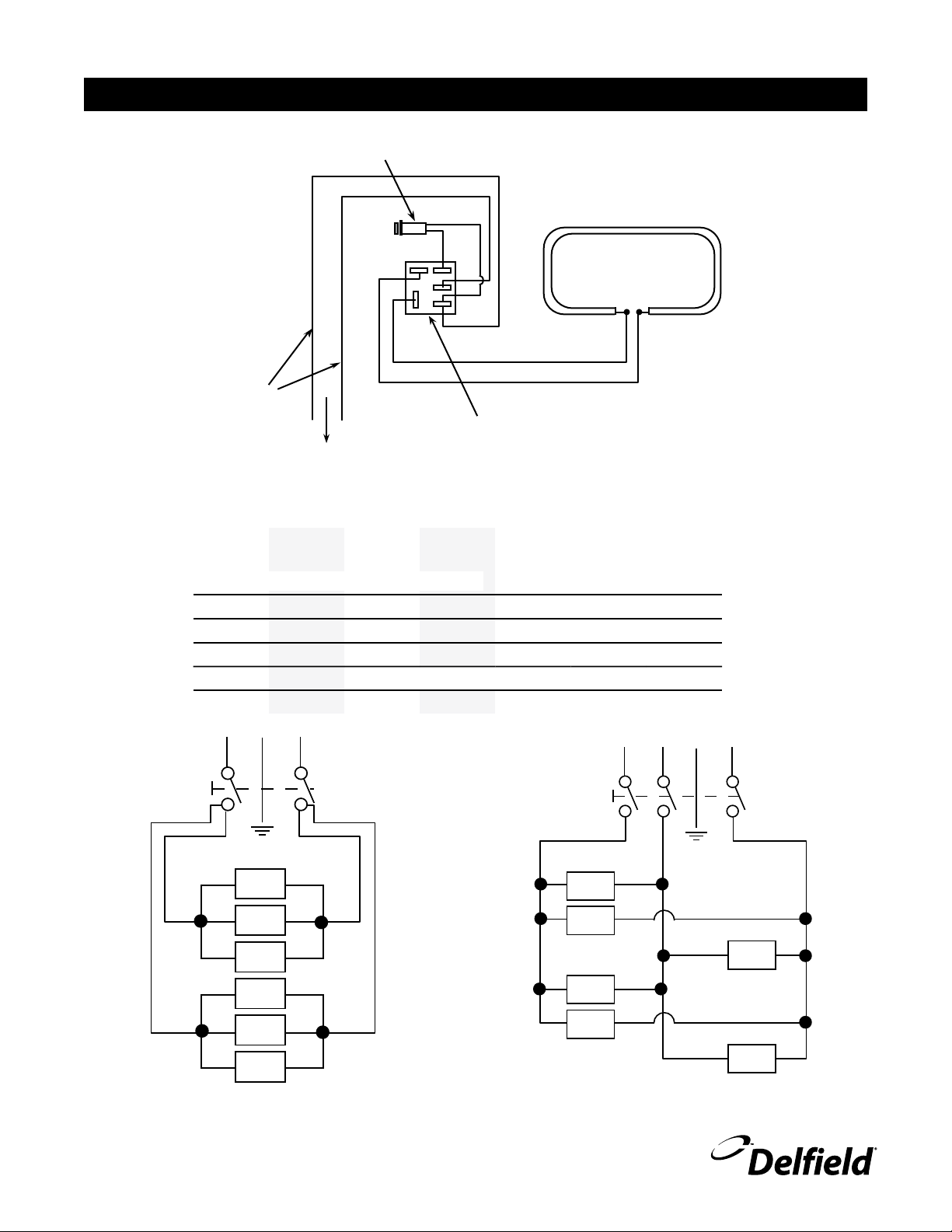
1000 W - 120V
OR 1000/1222 W -
208-230 V
HEATING ELEMENT
PILOT LIGHT
(FURNISHED)
INFINITE CONTROL
WITH “OFF”
POSITION
TO ADDITIONAL
FOOD WARMERS
LINE
WIRES
P
L1
L2
H1
H2
AMPERES
IN LINE
WIRES
208-230V, 3 PHASE
#
OF
WARMERS
120V,
1
PHASE
208V,
1 PHASE
230V,
1
PHASE
L1 L2 L3
1
8.3 4.8 5.3
2
16.7 9.6 10.6
3
25 14.4 15.9 14.4/15.9
4
33.3 19.2 21.3
5
24 26.6
6
28.8 31.3
19.2/21.3
24/26.1
28.8/31.3
14.4/15.9
14.4/15.9
19.2/21.3
19.2/21.3
14.4/15.9
19.2/21.3
28.8/31.3
28.8/31.3
Wiring Diagram, Heated Serving Counter
12
For customer service, call (800) 733-8829, (800) 773-8821, Fax (989) 773-3210, www.delfield.com
Standard Single Phase Optional Three Phase
Page 13

Concepts Use & Care Manual
COOLING T'STAT
CONDENSER FAN
COMPRESSOR
115V
L1
N
G
S
C
R
ON/OFF SWITCH
CONDENSER FAN
COMPRESSOR
115V
S
C
R
L1
N
G
COOLING T'STAT
CONDENSER FAN
COMPRESSOR
120V
L1
N
S
C
R
G
ON/OFF SWITCH
Wiring Diagram, Self-Contained Mechanically Cooled Serving Counter
Wiring Diagram, Self-Contained LiquiTec® Cold Pan Serving Counter
Wiring Diagram Self-Contained Frost Top Serving Counter
13
For customer service, call (800) 733-8829, (800) 773-8821, Fax (989) 773-3210, www.delfield.com
Page 14

Concepts Use & Care Manual
Standard Labor Guidelines To Repair Or Replace Parts On Delfield Equipment
Advice and recommendations given by Delfield Service Technicians do not constitute or guarantee any special coverage.
• A maximum of 1-hour is allowed to diagnose a defective component.
• A maximum of 1-hour is allowed for retrieval of parts not in stock.
• A maximum travel distance of 100 miles round trip and 2-hours will be reimbursed.
• Overtime, installation/start-up, normal control adjustments, general maintenance, glass breakage, freight damage, and/or
correcting and end-user installation error will not be reimbursed under warranty unless pre-approved with a Service Work
Authorization from Delfield. You must submit the number with the service claim.
LABOR OF 1-HOUR IS ALLOWED TO REPLACE:
• Thermostat • Contactor/Relay
• Infinite Switch • Transformer
• Door Jamb Switch • Evaporator/Condenser Fan Motor and Blade
• Solenoid Coil • Circulating Fan Motor and Blade
• Hi-limit/Thermal Protector Switch • Fan Delay/Defrost Termination Switch
• Compressor Start Components and Overload Protector • Door Hinges, Locks, and Gaskets
• Defrost Timer • Condensate Element
• Thermometer • Springs/Lowerator
LABOR OF 2 HOURS TO REPLACE:
• Drawer Tracks/Cartridges • Defrost Element
• Pressure Control • Heating Element
• Solenoid Valve • Locate/Repair Leak
LABOR OF 3 HOURS TO REPLACE:
• EPR or CPR Valve • Condenser or Evaporator Coil
• Expansion Valve
LABOR OF 4 HOURS TO REPLACE
• Compressor
This includes recovery of refrigerant and leak check.
$55.00 maximum reimbursement for refrigerant recovery (includes recovery machine, pump, torch, oil, flux, minor fittings,
solder, brazing rod, nitrogen, or similar fees.)
REFRIGERANTS
• R22 A maximum of $4.00/lb. or 25¢/oz. will be reimbursed.
• R134A A maximum of $5.00/lb. or 31¢/oz. will be reimbursed.
• R404A A maximum of $15.00/lb. or $1.00/oz. will be reimbursed.
14
For customer service, call (800) 733-8829, (800) 773-8821, Fax (989) 773-3210, www.delfield.com
Page 15

Parts List
Ice Cooled Units
243-ALS-003E Bar, Divider, 21" x .90"
3234242 Drain, Plastic
265-102-0030 Perforated Bottom
Built-In Cold Pans
3526999 Compressor, Danfoss
3516454 Condenser Coil
3516225 Expansion Valve, 1/4 Ton
3516457 Fan Blade
2160020 Fan Guard
2162717 Fan Motor
3516322 Filter Drier
3234242 Plastic Drain
3516444 Relay, Overload, Compressor
Concepts Use & Care Manual
2190154 Rocker Switch
2194787 Start Capacitor, Compressor
2194201 Thermostat
Drop-In Cold Pans
243-ALS-003E Bar, Divider, 21" x .90"
3526695 Compressor, 1/4 HP
3516067 Condenser Coil
2194013 Fan Assy, 8 Blade
3516191 Filter Drier
3234242 Plastic Drain
2194099 Switch
3516047 Temp Control
Heated Steam Tables
3234572 Drain Screen
2194007 Heating Element, 208V
2194095 Indicator Light, Amber
2194110 Innite Control, 208/240V
3234557 Knob
2194335 Safety Thermostat
2194212 Switch
For customer service, call (800) 733-8829, (800) 773-8821, Fax (989) 773-3210, www.delfield.com
15
Page 16

Concepts Use & Care Manual
Standard One Year Warranty (One year parts and labor.)
The Delfield Company (“Delfield”) warrants to the Original
Purchaser of the Delfield product (herein called the “Unit”)
that such Unit, and all parts thereof, will be free from defects
in material and workmanship under normal use and service
for a period of one (1) year from the date of shipment of the
Unit to the Original Purchaser or, if the Original Purchaser
returns the warranty card completely filled out including the
date of installation within thirty (30) days of receipt of the
Unit, one (1) year from the date of installation. During this
one year warranty period, Delfield will repair or replace any
defective part or portion there of returned to Delfield by the
Original Purchaser which Delfield determines was defective
due to faulty material or workmanship. During this one year
warranty period, Delfield will pay labor, crating, and freight
incurred in the removal of the Unit of defective component
and shipment to Delfield. A maximum of 1-hour is allowed
to diagnose a defective component. A maximum of 1-hour
is allowed for retrieval of parts not in stock. A maximum
travel distance of 100 miles round trip and 2-hours will be
reimbursed. Overtime, installation/start-up, normal control
adjustments, general maintenance, glass breakage, freight
damage, and/or correcting and end-user installation error will
not be reimbursed under warranty unless pre-approved with a
Service Work Authorization from Delfield. Delfield will pay the
return costs if the Unit or part thereof was defective.
The term “Original Purchaser” as used herein means that
person, firm, association, or corporation for whom the Unit was
originally installed.
This warranty does not apply to any Unit or part thereof that
has been subjected to misuse, neglect, alteration, or accident,
such as accidental damage to the exterior finish, operated
contrary to the recommendations specified by Delfield; or
repaired or altered by anyone other than Delfield in any way
so as to, in Delfield’s sole judgement, affect its quality or
efficiency. This warranty does not apply to any Unit that has
been moved from the location where it was originally installed.
This warranty also does not cover the refrigerator drier or the
light bulbs used in the Unit. The warranty is subject to the
user’s normal maintenance and care responsibility as set forth
in the Service and Installation Manual, such as cleaning the
condenser coil, and is in lieu of all other obligations of Delfield.
Delfield neither assumes, nor authorizes any other person
to assume for Delfield, any other liability in connection with
Delfield’s products.
Removal or defacement of the original Serial Number or Model
Number from any Unit shall be deemed to release Delfield from
all obligations hereunder or any other obligations, express or
implied.
If shipment of a replacement part is requested prior to the
arrival in the Delfield factory of the part claimed to be defective,
the Original Purchaser must accept delivery of the replacement
part of a C.O.D. basis, with credit being issued after the part
has been received and inspected at Delfield’s plant and
determined by Delfield to be within this warranty.
Under no condition does this warranty give the Original
Purchaser the right to replace the defective Unit with a complete
Unit of the same manufacturer or of another make. Unless
authorized by Delfield in writing, this warranty does not permit
the replacement of any part, including the motor-compressor,
to be made with the part of another make or manufacturer.
No claims can be made under this warranty for spoilage of any
products for any reason, including system failure.
The installation contractor shall be responsible for building
access, entrance and field conditions to insure sufficient
clearance to allow any hood(s), vent(s), or Unit(s) if necessary,
to be brought into the building. Delfield will not be responsible
for structural changes or damages incurred during installation
of the Unit or any exhaust system.
Delfield shall not be liable in any manner for any default or
delay in performance hereunder caused by or resulting from
any contingency beyond Delfield’s control, including, but not
limited to, war, governmental restrictions or restraints, strike,
lockouts, injunctions, fire, flood, acts of nature, short or reduced
supply of raw materials, or discontinuance of the parts by the
original part manufacturer.
Except as provided in any Additional Four Year Protection
Plan, if applicable, and the Service Labor Contract, if
applicable, the foregoing is exclusive and in lieu of all other
warranties, whether written or oral, express or implied. This
warranty supersedes and excludes any prior oral or written
representations or warranties. Delfield expressly disclaims any
implied warranties of merchantability, fitness for a particular
purpose of compliance with any law, treaty, rule or regulation
relating to the discharge of substances into the environment.
The sole and exclusive remedies of any person relating to
the Unit, and the full liability of Delfield for any breach of this
warranty, will be as provided in this warranty.
Other than this Delfield Standard One Year Limited Warranty,
any applicable Delfield Additional Four Year Protection Plan
or applicable Delfield Service Labor Contract, the Original
Purchaser agrees and acknowledges that no other warranties
are offered or provided in connection with or for the unit or any
other part thereof.
Parts furnished by suppliers to Delfield are guaranteed by
Delfield only to the extent of the original manufacturer’s
express warranty to Delfield. Failure of the Original Purchaser
to receive such manufacturer’s express warranty to Delfield.
Failure of the Original Purchaser to receive such manufacturers
warranty shall in no way create any warranty, expressed or
implied, or any other obligation or liability on Delfield’s part in
respect thereof.
16
For customer service, call (800) 733-8829, (800) 773-8821, Fax (989) 773-3210, www.delfield.com
In no event will Delfield be liable for special, incidental or
consequential damages, or for damages in the nature of
penalties.
Page 17

Additional Four Year Protection Plan (for Motor-Compressor only)
Installation
Delfield Model# Serial # Date
Concepts Use & Care Manual
In addition to the Standard One Year Warranty on the MotorCompressor contained in the above listed Delfield product (the
“Unit”), The Delfield Company (“Delfield”) also agrees to repair, or
exchange with similar or interchangeable parts in design and capacity
at Delfield’s option, the defective Motor-Compressor contained in the
Unit (the “Motor-Compressor), or any part thereof, for the Original
Purchaser only, at any time during the four (4) years following the
initial one (1) year period commencing on the date of installation for
the Original Purchaser. Failure of the Original Purchaser to register
the registration card containing the Original Purchasers name,
address, date of installation, model number and serial number
of the Unit containing the Motor-Compressor within 30 days from
the date of installation shall void this warranty. This additional
warranty is only available if the Motor-Compressor is inoperative
due to defects in material or factory workmanship, as determined by
Delfield in its sole judgement and discretion. The Original Purchaser
shall be responsible for returning the defective Motor-Compressor to
Delfield prepaid, F.O.B. at the address shown on the back cover of this
manual.
The term “Original Purchaser” as used herein means that person,
firm, association, or corporation for whom the Unit was originally
installed.
The term “Motor-Compressor” as used herein does not include unit
base, air or water cooled condenser, receiver, electrical accessories
such as relay, capacitors, refrigerant controls, or condenser fan/motor
assembly. This warranty does not cover labor charges incidental to
the replacement of parts. This warranty further does not include
any equipment to which said condensing unit is connected, such as
cooling coils, temperature controls or refrigerant metering devices.
This warranty shall be void if the Motor-Compressor, in Delfield’s
sole judgement, has been subjected to misuse, neglect, alteration or
accident, operated contrary to the recommendations specified by the
Unit manufacturer, repaired or altered by anyone other than Delfield
in any way so as, in Delfield’s sole judgment, to affect its quality or
efficiency or if the serial number has been altered, defaced or removed.
This Warranty does not apply to a Motor-Compressor in any Unit that
has been moved from the location where it was originally installed.
The addition of methyl chloride to the condensing unit or refrigeration
system shall void this warranty.
General Conditions
Delfield shall not be liable in any manner for any default or delay in
performance hereunder caused by or resulting from any contingency
beyond Delfield’s control, including, but not limited to, war,
governmental restrictions or restraints, strike, lockouts, injunctions,
fire, flood, acts of nature, short or reduced supply of raw materials,
or discontinuance of any part or the Motor-Compressor by the unit
manufacturer.
Replacement of a defective Motor-Compressor is limited to one (1)
Motor-Compressor by us during the four (4) year period. Delfield
shall replace the Motor-Compressor at no charge.
This warranty does not give the Original Purchaser of the MotorCompressor the right to purchase a complete replacement MotorCompressor of the same make or of another make. It further does
not permit the replacement to be made with a Motor-Compressor
of another kind unless authorized by Delfield. In the event Delfield
authorizes the Original Purchaser to purchase a replacement MotorCompressor locally, only the wholesale cost of the Motor-Compressor
is refundable.
Expressly excluded from this warranty are damages resulting from
spoilage of goods.
Except as provided in any applicable Standard One Year Limited
Warranty or applicable Service Labor Contract, the foregoing is
exclusive and in lieu of all other warranties, whether written or
oral, express or implied. This Warranty supersedes and excludes
any prior oral or written representations or warranties. Delfield
expressly disclaims any implied warranties of merchantability,
fitness for a particular purpose or compliance with any law, treaty,
rule or regulation relating to the Motor-Compressor, and the full
liability of Delfield for any breach of this warranty, will be as
provided in this warranty.
Other than any applicable Delfield Standard One year Limited Warranty,
this Delfield Additional Four Year Protection Plan and any applicable
Delfield Service Labor Contract, the Original Purchaser agrees and
acknowledges that no other warranties are offered or provided in
connection with or for the Motor-Compressor or any part thereof.
In no event will Delfield be liable for special, incidental or consequential
damages, or for damages in the nature of penalties.
For customer service, call (800) 733-8829, (800) 773-8821, Fax (989) 773-3210, www.delfield.com
17
Page 18

Concepts Use & Care Manual
Notes
18
For customer service, call (800) 733-8829, (800) 773-8821, Fax (989) 773-3210, www.delfield.com
Page 19

Notes
Concepts Use & Care Manual
For customer service, call (800) 733-8829, (800) 773-8821, Fax (989) 773-3210, www.delfield.com
19
Page 20

Mt. Pleasant, MI Covington, TN
Thank you for choosing Delfield!
Help is a phone call away. Help our team of professional, courteous customer service
reps by having your model number and serial number available at the time
of your call (800) 733-8829
Model: ____________________ S/N: ____________________
Installation Date: __________________
For a list of Delfield’s authorized parts depots,
visit our website at www.delfield.com
980 S. Isabella Rd., Mt. Pleasant, MI 48858, U.S.A. • (989) 773-7981 or (800) 733-8829 • Fax (989) 773-3210 • www.delfield.com
Delfield reserves the right to make changes in design or specifications without prior notice. ©2010 The Delfield Company. All rights reserved. Printed in the U.S.A.
DMConcepts 06/10
 Loading...