


 Loading...
Delem Machine Parameters
Version 3
DA-65W DA-66W DA-69W
Manual version V0908

PREFACE
In this machine parameter manual you find the explanation on:
•the input and output signals (X- and Y-axis and general);
•the selection possibilities of the machine parameter menu;
•the value and function of the machine parameters of the X- and Y-axis;
•the auxiliary axes with corresponding parameters.
The first chapter describes the function of the general input and output signals and the input and output signals of the X- and Y-axis and in what way these signals should be connected to the axis module.
The High Speed Bus (HSB) takes care of the communication between the control and the modules. Via this HSB line the modules are programmed with the appropriate machine parameter values to control the axes. The programmed values of the axes are compared with the actual axes positions and the machine parameter settings. If the 'new' values are within the range the 'new' values become the actual values.
The machine parameters (including all axis parameters) are programmed in the machine parameter menu of the control. Besides the programming of the machine parameters you have several other selection possibilities in this machine parameter menu. These selection possibilities are explained in chapter 2.
The basic machine parameters are to control the Y-axis. In chapters 3 and 4 these machine parameters are explained. The explanation comprises the parameter range, the default value, the parameter function and a description.
From chapter 5 until chapter 10 the parameters of the auxiliary axes and special functions are given. The auxiliary axes are grouped per type of axis. The next type of axes and special functions are explained:
•
•
•
•
•
•
auxiliary axes (chapter 5);
axes types and parameters (chapter 6); crowning (chapter 7);
digital outputs (chapter 8); I-axes (chapter 9);
part support (chapter 10);
This manual is valid for the following Delem control types:
•
•
•
DA-65W (V3) DA-66W (V3) DA-69W (V3)
V0908, 0.2

Table of contents
1. Input and output signals . . . . . . . . . . . . . . . . . . . . . . . . . . . . . . . . . . . . . 1.1
1.1. Introduction . . . . . . . . . . . . . . . . . . . . . . . . . . . . . . . . . . . . . . . . . . . . . . . . . 1.1 1.2. Y-axis input signals . . . . . . . . . . . . . . . . . . . . . . . . . . . . . . . . . . . . . . . . . . 1.1 1.3. Y-axis output signals . . . . . . . . . . . . . . . . . . . . . . . . . . . . . . . . . . . . . . . . . 1.2 1.4. X-axis signals . . . . . . . . . . . . . . . . . . . . . . . . . . . . . . . . . . . . . . . . . . . . . . . 1.4 1.5. Axis signals . . . . . . . . . . . . . . . . . . . . . . . . . . . . . . . . . . . . . . . . . . . . . . . . 1.4 1.6. Various input and output signals . . . . . . . . . . . . . . . . . . . . . . . . . . . . . . . . 1.4 1.7. Conventional systems . . . . . . . . . . . . . . . . . . . . . . . . . . . . . . . . . . . . . . . 1.11
2. Machine parameters menu . . . . . . . . . . . . . . . . . . . . . . . . . . . . . . . . . . . . 2.1
2.1. Introduction . . . . . . . . . . . . . . . . . . . . . . . . . . . . . . . . . . . . . . . . . . . . . . . . . 2.1 2.2. Selection procedure of machine parameters menu . . . . . . . . . . . . . . . . . . 2.1 2.3. General parameters . . . . . . . . . . . . . . . . . . . . . . . . . . . . . . . . . . . . . . . . . . 2.2 2.4. Y-axis parameters . . . . . . . . . . . . . . . . . . . . . . . . . . . . . . . . . . . . . . . . . . . 2.2 2.5. Auxiliary Axes . . . . . . . . . . . . . . . . . . . . . . . . . . . . . . . . . . . . . . . . . . . . . . . 2.2 2.6. Module configuration . . . . . . . . . . . . . . . . . . . . . . . . . . . . . . . . . . . . . . . . . 2.2 2.7. Machine parameters backup . . . . . . . . . . . . . . . . . . . . . . . . . . . . . . . . . . . 2.3 2.8. Changing the access code . . . . . . . . . . . . . . . . . . . . . . . . . . . . . . . . . . . . . 2.4 2.9. Options . . . . . . . . . . . . . . . . . . . . . . . . . . . . . . . . . . . . . . . . . . . . . . . . . . . . 2.4 2.10. Gauge . . . . . . . . . . . . . . . . . . . . . . . . . . . . . . . . . . . . . . . . . . . . . . . . . . . . 2.5 2.11. Leaving the machine parameters menu . . . . . . . . . . . . . . . . . . . . . . . . . . 2.5
3. General parameters . . . . . . . . . . . . . . . . . . . . . . . . . . . . . . . . . . . . . . . . . 3.1
3.1. Introduction . . . . . . . . . . . . . . . . . . . . . . . . . . . . . . . . . . . . . . . . . . . . . . . . . 3.1 3.2. The Machine page . . . . . . . . . . . . . . . . . . . . . . . . . . . . . . . . . . . . . . . . . . . 3.2 3.3. Tools page . . . . . . . . . . . . . . . . . . . . . . . . . . . . . . . . . . . . . . . . . . . . . . . . 3.15 3.4. Serial ports page . . . . . . . . . . . . . . . . . . . . . . . . . . . . . . . . . . . . . . . . . . . 3.21 3.5. Sequencer page . . . . . . . . . . . . . . . . . . . . . . . . . . . . . . . . . . . . . . . . . . . . 3.24
4. Y-axis parameters . . . . . . . . . . . . . . . . . . . . . . . . . . . . . . . . . . . . . . . . . . . 4.1
4.1. |
Introduction . . . . . . . . . . . . . . . . . . . . . . . . . . . . . . . . . . . . . . . . . . . . . . . . . |
4.1 |
4.2. |
Parameters for a KO-table in the 7000-range . . . . . . . . . . . . . . . . . . . . . . |
4.2 |
4.2.1. Introduction . . . . . . . . . . . . . . . . . . . . . . . . . . . . . . . . . . . . . . . . . . . . . . . . . . . 4.2 4.2.2. The General page . . . . . . . . . . . . . . . . . . . . . . . . . . . . . . . . . . . . . . . . . . . . . . 4.3 4.2.3. The Feedback page . . . . . . . . . . . . . . . . . . . . . . . . . . . . . . . . . . . . . . . . . . . 4.15 4.2.4. The Pressure valve page . . . . . . . . . . . . . . . . . . . . . . . . . . . . . . . . . . . . . . . 4.20 4.2.5. The Pressure sensors page . . . . . . . . . . . . . . . . . . . . . . . . . . . . . . . . . . . . . 4.31 4.2.6. The Closing page . . . . . . . . . . . . . . . . . . . . . . . . . . . . . . . . . . . . . . . . . . . . . 4.39 4.2.7. The Pressing page . . . . . . . . . . . . . . . . . . . . . . . . . . . . . . . . . . . . . . . . . . . . 4.54 4.2.8. The Decompression page . . . . . . . . . . . . . . . . . . . . . . . . . . . . . . . . . . . . . . 4.66 4.2.9. The Opening page . . . . . . . . . . . . . . . . . . . . . . . . . . . . . . . . . . . . . . . . . . . . 4.74
4.3. Y-axis adjustment procedure . . . . . . . . . . . . . . . . . . . . . . . . . . . . . . . . . . 4.85
4.3.1. Introduction . . . . . . . . . . . . . . . . . . . . . . . . . . . . . . . . . . . . . . . . . . . . . . . . . . 4.85 4.3.2. Analysis tool . . . . . . . . . . . . . . . . . . . . . . . . . . . . . . . . . . . . . . . . . . . . . . . . . 4.85 4.3.3. General preparations Y-axis . . . . . . . . . . . . . . . . . . . . . . . . . . . . . . . . . . . . . 4.86 4.3.4. Fast closing . . . . . . . . . . . . . . . . . . . . . . . . . . . . . . . . . . . . . . . . . . . . . . . . . 4.86 4.3.5. Pressing . . . . . . . . . . . . . . . . . . . . . . . . . . . . . . . . . . . . . . . . . . . . . . . . . . . . 4.89 4.3.6. Decompression . . . . . . . . . . . . . . . . . . . . . . . . . . . . . . . . . . . . . . . . . . . . . . . 4.90 4.3.7. Opening . . . . . . . . . . . . . . . . . . . . . . . . . . . . . . . . . . . . . . . . . . . . . . . . . . . . 4.90
4.4. Parameters for other KO-tables . . . . . . . . . . . . . . . . . . . . . . . . . . . . . . . . 4.92
V0908, 0.3

4.4.1. Introduction . . . . . . . . . . . . . . . . . . . . . . . . . . . . . . . . . . . . . . . . . . . . . . . . . . 4.92 4.4.2. The General page . . . . . . . . . . . . . . . . . . . . . . . . . . . . . . . . . . . . . . . . . . . . . 4.93 4.4.3. Feedback page . . . . . . . . . . . . . . . . . . . . . . . . . . . . . . . . . . . . . . . . . . . . . . 4.107 4.4.4. Pressure valve page . . . . . . . . . . . . . . . . . . . . . . . . . . . . . . . . . . . . . . . . . . 4.108 4.4.5. Pressure sensors page . . . . . . . . . . . . . . . . . . . . . . . . . . . . . . . . . . . . . . . . 4.109 4.4.6. Fast closing page . . . . . . . . . . . . . . . . . . . . . . . . . . . . . . . . . . . . . . . . . . . . 4.111 4.4.7. Pressing page . . . . . . . . . . . . . . . . . . . . . . . . . . . . . . . . . . . . . . . . . . . . . . . 4.124 4.4.8. Dwell time (level 3 only) . . . . . . . . . . . . . . . . . . . . . . . . . . . . . . . . . . . . . . . 4.136 4.4.9. Decompression (level 3 only) . . . . . . . . . . . . . . . . . . . . . . . . . . . . . . . . . . . 4.139 4.4.10. Opening page . . . . . . . . . . . . . . . . . . . . . . . . . . . . . . . . . . . . . . . . . . . . . . 4.146 4.4.11. Manual movement (level 3 only) . . . . . . . . . . . . . . . . . . . . . . . . . . . . . . . . 4.157
4.5. Conventional parameters . . . . . . . . . . . . . . . . . . . . . . . . . . . . . . . . . . . |
4.161 |
4.5.1. Introduction . . . . . . . . . . . . . . . . . . . . . . . . . . . . . . . . . . . . . . . . . . . . . . . . . 4.161 4.5.2. General page . . . . . . . . . . . . . . . . . . . . . . . . . . . . . . . . . . . . . . . . . . . . . . . 4.162 4.5.3. Feedback page . . . . . . . . . . . . . . . . . . . . . . . . . . . . . . . . . . . . . . . . . . . . . . 4.165 4.5.4. Output page . . . . . . . . . . . . . . . . . . . . . . . . . . . . . . . . . . . . . . . . . . . . . . . . 4.170
5. Auxiliary axes . . . . . . . . . . . . . . . . . . . . . . . . . . . . . . . . . . . . . . . . . . . . . |
. 5.1 |
5.1. Introduction . . . . . . . . . . . . . . . . . . . . . . . . . . . . . . . . . . . . . . . . . . . . . . . . |
5.1 |
5.2. Configuration procedure of modules . . . . . . . . . . . . . . . . . . . . . . . . . . . . . |
5.2 |
5.3. Backgauge finger configuration . . . . . . . . . . . . . . . . . . . . . . . . . . . . . . . . . |
5.5 |
5.4. Configuration procedure of axes . . . . . . . . . . . . . . . . . . . . . . . . . . . . . . . . |
5.9 |
5.5. R-axis specific parameters . . . . . . . . . . . . . . . . . . . . . . . . . . . . . . . . . . . |
5.11 |
5.6. Z-axis specific parameters . . . . . . . . . . . . . . . . . . . . . . . . . . . . . . . . . . . . |
5.12 |
5.7. Parameters for a servo axis . . . . . . . . . . . . . . . . . . . . . . . . . . . . . . . . . . . |
5.15 |
5.8. Parameters AC axes . . . . . . . . . . . . . . . . . . . . . . . . . . . . . . . . . . . . . . . . |
5.15 |
5.9. X1X2 difference programming (option) . . . . . . . . . . . . . . . . . . . . . . . . . . |
5.18 |
5.10. The spindle correction table . . . . . . . . . . . . . . . . . . . . . . . . . . . . . . . . . |
5.19 |
6. Auxiliary axes parameters . . . . . . . . . . . . . . . . . . . . . . . . . . . . . . . . . . . . 6.1
6.1. Introduction . . . . . . . . . . . . . . . . . . . . . . . . . . . . . . . . . . . . . . . . . . . . . . . . 6.1 6.2. The General page . . . . . . . . . . . . . . . . . . . . . . . . . . . . . . . . . . . . . . . . . . . 6.1 6.3. The feedback page . . . . . . . . . . . . . . . . . . . . . . . . . . . . . . . . . . . . . . . . . . 6.9 6.4. The Control page . . . . . . . . . . . . . . . . . . . . . . . . . . . . . . . . . . . . . . . . . . . 6.21 6.5. Control fine tuning . . . . . . . . . . . . . . . . . . . . . . . . . . . . . . . . . . . . . . . . . . 6.33 6.6. The output page . . . . . . . . . . . . . . . . . . . . . . . . . . . . . . . . . . . . . . . . . . . 6.36 6.7. The safety page . . . . . . . . . . . . . . . . . . . . . . . . . . . . . . . . . . . . . . . . . . . . 6.52
7. Crowning . . . . . . . . . . . . . . . . . . . . . . . . . . . . . . . . . . . . . . . . . . . . . . . . . . 7.1
7.1. Introduction . . . . . . . . . . . . . . . . . . . . . . . . . . . . . . . . . . . . . . . . . . . . . . . . 7.1 7.2. Hydraulic crowning device . . . . . . . . . . . . . . . . . . . . . . . . . . . . . . . . . . . . . 7.2
7.2.1. Introduction . . . . . . . . . . . . . . . . . . . . . . . . . . . . . . . . . . . . . . . . . . . . . . . . . . . 7.2 7.2.2. Hydraulic crowning parameters . . . . . . . . . . . . . . . . . . . . . . . . . . . . . . . . . . . 7.3 7.2.3. Hydraulic crowning adjustment . . . . . . . . . . . . . . . . . . . . . . . . . . . . . . . . . . . 7.17
7.3. Motorised crowning AC . . . . . . . . . . . . . . . . . . . . . . . . . . . . . . . . . . . . . . 7.18
7.3.1. Introduction . . . . . . . . . . . . . . . . . . . . . . . . . . . . . . . . . . . . . . . . . . . . . . . . . . 7.18 7.3.2. Parameters AC crowning . . . . . . . . . . . . . . . . . . . . . . . . . . . . . . . . . . . . . . . 7.19 7.3.3. Crowning device adjustment for computed purposes . . . . . . . . . . . . . . . . . . 7.23 7.3.4. Crowning device adjustment for non-computed purposes . . . . . . . . . . . . . . 7.24
7.4. Dynamic crowning . . . . . . . . . . . . . . . . . . . . . . . . . . . . . . . . . . . . . . . . . . 7.25
7.4.1. Introduction . . . . . . . . . . . . . . . . . . . . . . . . . . . . . . . . . . . . . . . . . . . . . . . . . . 7.25 7.4.2. Parameters . . . . . . . . . . . . . . . . . . . . . . . . . . . . . . . . . . . . . . . . . . . . . . . . . . 7.26 7.4.3. Dynamic crowning adjustment . . . . . . . . . . . . . . . . . . . . . . . . . . . . . . . . . . . 7.28
8. Digital outputs . . . . . . . . . . . . . . . . . . . . . . . . . . . . . . . . . . . . . . . . . . . . . . 8.1
V0908, 0.4

8.1. Introduction . . . . . . . . . . . . . . . . . . . . . . . . . . . . . . . . . . . . . . . . . . . . . . . . . 8.1 8.2. Digital R-axis . . . . . . . . . . . . . . . . . . . . . . . . . . . . . . . . . . . . . . . . . . . . . . . 8.1 8.3. On/off outputs . . . . . . . . . . . . . . . . . . . . . . . . . . . . . . . . . . . . . . . . . . . . . . . 8.5
9. I-axes . . . . . . . . . . . . . . . . . . . . . . . . . . . . . . . . . . . . . . . . . . . . . . . . . . . . . 9.1
9.1. Introduction . . . . . . . . . . . . . . . . . . . . . . . . . . . . . . . . . . . . . . . . . . . . . . . . . 9.1 9.2. I-axis with 1 speed AC motor with potentiometer feedback . . . . . . . . . . . . 9.1 9.3. Digital I-axis parameters . . . . . . . . . . . . . . . . . . . . . . . . . . . . . . . . . . . . . . . 9.3
10. Part support . . . . . . . . . . . . . . . . . . . . . . . . . . . . . . . . . . . . . . . . . . . . . . 10.1
10.1. Introduction . . . . . . . . . . . . . . . . . . . . . . . . . . . . . . . . . . . . . . . . . . . . . . . 10.1 10.2. Parameters digital part support . . . . . . . . . . . . . . . . . . . . . . . . . . . . . . . 10.2 10.3. Adjustment procedures . . . . . . . . . . . . . . . . . . . . . . . . . . . . . . . . . . . . 10.28 10.4. Extra info and recommendations . . . . . . . . . . . . . . . . . . . . . . . . . . . . . 10.31 10.5. Additional part support axes . . . . . . . . . . . . . . . . . . . . . . . . . . . . . . . . . 10.34
V0908, 0.5

V0908, 0.6

Parameter index
This appendix contains a list of all parameters described in this manual, in alphabetic order.
Acceleration ramp . . . . . . . . . . . . . . . . .6.39 Acceleration, 0 to max. speed . . . . . . . .4.41 Acceleration, 0 to max. speed . . . . . . . .4.56 Acceleration, 0 to max. speed . . . . . . . .4.67 Acceleration, 0 to max. speed . . . . . . . .4.76 Acceleration, 0 to max. speed . . . . . . . .6.28 Adjustment mode . . . . . . . . . . . . . . . . . .10.6 AD-max . . . . . . . . . . . . . . . . . . . . . . . . .6.20 AD-max . . . . . . . . . . . . . . . . . . . . . . . . .7.21 AD-min . . . . . . . . . . . . . . . . . . . . . . . . . .6.19 AD-min . . . . . . . . . . . . . . . . . . . . . . . . . .7.20 Anti backbend dist. . . . . . . . . . . . . . . . .4.171 Automatic R-axis correction (0/1) . . . . . .7.10 Axis retract programmable . . . . . . . . . . . .6.8 Axis speed programmable . . . . . . . . . . . .6.7 Balance pressure . . . . . . . . . . . . . . . . . .4.34 Braking Ramp . . . . . . . . . . . . . . . . . . . .6.51 Braking time max . . . . . . . . . . . . . . . . .4.102 Braking time max . . . . . . . . . . . . . . . . . .4.12 Break point high speed (Bfs)< . . . . . . . .6.45 Break point high speed (Bfs)> . . . . . . . .6.43 Break point low speed (Bss)< . . . . . . . .6.44 Break point low speed (Bss)> . . . . . . . .6.42 Calibrate valves . . . . . . . . . . . . . . . . . .4.103 Calibrate valves . . . . . . . . . . . . . . . . . . .4.13 Calibration . . . . . . . . . . . . . . . . . . . . . . .4.22 Closing brake ramp . . . . . . . . . . . . . . .4.119 Closing brake ramp trim . . . . . . . . . . . .4.117 Closing gain . . . . . . . . . . . . . . . . . . . . .4.120 Closing gain trim . . . . . . . . . . . . . . . . .4.118 Closing parallelism gain . . . . . . . . . . . .4.121 Closing pressure . . . . . . . . . . . . . . . . .4.122 Closing ramp offset . . . . . . . . . . . . . . .4.115 Closing speed . . . . . . . . . . . . . . . . . . .4.112 Closing speed incr. . . . . . . . . . . . . . . .4.113 Control margin . . . . . . . . . . . . . . . . . . . .4.35 Count direction . . . . . . . . . . . . . . . . . . .4.169 Count direction . . . . . . . . . . . . . . . . . . . .6.18 Count direction left (Y1) . . . . . . . . . . . . .4.18 Count direction right (Y2) . . . . . . . . . . . .4.19 Crowning set before bending . . . . . . . . . .7.5 Crowning value . . . . . . . . . . . . . . . . . . . .7.4 DA-max . . . . . . . . . . . . . . . . . . . . . . . . .7.16 DA-min . . . . . . . . . . . . . . . . . . . . . . . . . .7.15 DA-out linear/table . . . . . . . . . . . . . . . . .7.14 Dc high speed < . . . . . . . . . . . . . . . . . . .6.48 Dc high speed > . . . . . . . . . . . . . . . . . . .6.50 Dc low speed < . . . . . . . . . . . . . . . . . . .6.47 Dc low speed > . . . . . . . . . . . . . . . . . . .6.49 Deceleration, max. speed to 0 . . . . . . . .4.42 Deceleration, max. speed to 0 . . . . . . . .4.57
Deceleration, max. speed to 0 . . . . . . . 4.68 Deceleration, max. speed to 0 . . . . . . . 4.77 Deceleration, max. speed to 0 . . . . . . . 6.29 Decimal point pos. . . . . . . . . . . . . . . . . . 6.2 Decimal point pos. . . . . . . . . . . . . . . . . . 7.6 Decompression gain . . . . . . . . . . . . . . 4.140 Decompression parallelism gain . . . . . 4.141 Decompression position offset . . . . . . 4.144 Decompression speed increment . . . . 4.143 Default value . . . . . . . . . . . . . . . . . . . . . 10.8 Default value . . . . . . . . . . . . . . . . . . . . . . 6.5 Default value . . . . . . . . . . . . . . . . . . . . . . 7.9 Default value . . . . . . . . . . . . . . . . . . . . . . 8.4 Default value . . . . . . . . . . . . . . . . . . . . . . 8.7 Del. before closing . . . . . . . . . . . . . . . 4.116 Del. before opening . . . . . . . . . . . . . . . 4.150 Delay after decompression . . . . . . . . . . 4.72 Delay at end of decompression . . . . . 4.142 Delay before closing . . . . . . . . . . . . . . . 4.47 Delay before opening . . . . . . . . . . . . . . 4.82 Delay before pressing . . . . . . . . . . . . . 4.126 Delay before pressing . . . . . . . . . . . . . . 4.63 Delay before pressing force . . . . . . . . 4.127 Delay before retour factor . . . . . . . . . . . 10.5 Die clamp pressure . . . . . . . . . . . . . . . . 3.20 Differential gain max . . . . . . . . . . . . . . 10.26 Differential gain min . . . . . . . . . . . . . . 10.25 Direction . . . . . . . . . . . . . . . . . . . . . . . . . 4.6 Direction . . . . . . . . . . . . . . . . . . . . . . . . 4.96 Direction pin up/down . . . . . . . . . . . . . . 6.41 Drive type . . . . . . . . . . . . . . . . . . . . . . . 6.25 Dwell time gain closing . . . . . . . . . . . . 4.137 Dwell time gain opening . . . . . . . . . . . 4.138 Dwell time programmable . . . . . . . . . . 4.163 Emergency deceleration time . . . . . . . . 6.30 Encoder mounted . . . . . . . . . . . . . . . . 4.166 External mute adjust . . . . . . . . . . . . . . 4.100 External mute adjust . . . . . . . . . . . . . . . 4.52 Feedforward friction value . . . . . . . . . . . 4.44 Feedforward friction value . . . . . . . . . . . 4.60 Feedforward friction value . . . . . . . . . . . 4.70 Feedforward friction value . . . . . . . . . . . 4.79 Feedforward gain max . . . . . . . . . . . . 10.24 Feedforward gain min . . . . . . . . . . . . . 10.23 Feedforward speed gain . . . . . . . . . . . . 4.45 Feedforward speed gain . . . . . . . . . . . . 4.61 Feedforward speed gain . . . . . . . . . . . . 4.71 Feedforward speed gain . . . . . . . . . . . . 4.80 Following error enabled . . . . . . . . . . . . 6.34 Following error margin . . . . . . . . . . . . . 6.35 Force maximum . . . . . . . . . . . . . . . . . . 4.24 Force Middle . . . . . . . . . . . . . . . . . . . . . 4.25 Force minimum . . . . . . . . . . . . . . . . . . . 4.26 Force programmable . . . . . . . . . . . . . . 4.164 Hysteresis . . . . . . . . . . . . . . . . . . . . . . . 7.22 Hysteresis mute-output . . . . . . . . . . . . 4.175 Hysteresis udp-output . . . . . . . . . . . . . 4.176 I-action gain . . . . . . . . . . . . . . . . . . . . 4.133
V0908, 0.7

I-gain . . . . . . . . . . . . . . . . . . . . . . . . . . 4.59 I-gain . . . . . . . . . . . . . . . . . . . . . . . . . . 6.32 In Position tolerance . . . . . . . . . . . . . . 10.7 In position tolerance . . . . . . . . . . . . . . . 6.37 Inertia under beam . . . . . . . . . . . . . . . . 3.11 Inertia upper beam . . . . . . . . . . . . . . . . 3.12 Ls FD output . . . . . . . . . . . . . . . . . . . . . 9.5 M_OPTION 1 - 64 . . . . . . . . . . . . . . . . 3.25 Machine length between cylinders . . . . 3.10 Machine name . . . . . . . . . . . . . . . . . . . . 3.8 Manual gain closing . . . . . . . . . . . . . . 4.158 Manual gain opening . . . . . . . . . . . . . 4.159 Manual parallelism gain . . . . . . . . . . . 4.160 Manual speed high . . . . . . . . . . . . . . . . . 6.6 Max. AD-value . . . . . . . . . . . . . . . . . . 10.18 Max. Angle . . . . . . . . . . . . . . . . . . . . . 10.11 Max. angle speed . . . . . . . . . . . . . . . . 10.13 Max. pressing speed . . . . . . . . . . . . . 4.125 Max. value . . . . . . . . . . . . . . . . . . . . . . . 6.4 Max. value . . . . . . . . . . . . . . . . . . . . . . . 7.8 Maximum . . . . . . . . . . . . . . . . . . . . . . . . 4.5 Maximum . . . . . . . . . . . . . . . . . . . . . . . 4.95 Maximum current . . . . . . . . . . . . . . . . . 7.13 Maximum I-action . . . . . . . . . . . . . . . . 4.134 Maximum operating speed . . . . . . . . . . 4.40 Maximum operating speed . . . . . . . . . . 4.55 Maximum operating speed . . . . . . . . . . 4.75 Maximum operating speed . . . . . . . . . . 6.27 Maximum valve pressure . . . . . . . . . . . 4.36 Maximum voltage . . . . . . . . . . . . . . . . . 7.12 Maximum Y1Y2 difference . . . . . . . . . . . 4.8 Maximum Y1Y2 difference . . . . . . . . . . 4.98 Mean angle speed high . . . . . . . . . . . 10.20 Mean angle speed low . . . . . . . . . . . . 10.19 Middle valve pressure . . . . . . . . . . . . . 4.37 Min. AD-value . . . . . . . . . . . . . . . . . . 10.17 Min. Angle . . . . . . . . . . . . . . . . . . . . . 10.10 Min. value . . . . . . . . . . . . . . . . . . . . . . . . 6.3 Min. value . . . . . . . . . . . . . . . . . . . . . . . . 7.7 Minimum . . . . . . . . . . . . . . . . . . . . . . . . 4.4 Minimum . . . . . . . . . . . . . . . . . . . . . . . 4.94 Minimum valve pressure . . . . . . . . . . . 4.38 Motor drive type . . . . . . . . . . . . . . . . . . 6.40 Mute changed tolerance . . . . . . . . . . . 4.51 Mute changed tolerance . . . . . . . . . . . 4.99 Mute programmable each step . . . . . . . 4.7 Mute programmable each step . . . . . . 4.97 Mute-2 offset . . . . . . . . . . . . . . . . . . . 4.123 Nbr positions . . . . . . . . . . . . . . . . . . . . . 9.4 Number of FD outputs . . . . . . . . . . . . . . 8.6 Number of slaves . . . . . . . . . . . . . . . . . 10.9 Offset ldp-output . . . . . . . . . . . . . . . . 4.173 Offset mute position . . . . . . . . . . . . . . . 4.49 Offset mute-2 output . . . . . . . . . . . . . . 4.50 Offset mute-output . . . . . . . . . . . . . . . 4.172 Offset udp-output . . . . . . . . . . . . . . . . 4.174 Opening brake ramp . . . . . . . . . . . . . 4.153 Opening gain . . . . . . . . . . . . . . . . . . . 4.154
Opening gain trim . . . . . . . . . . . . . . . . 4.152 Opening parallelism gain . . . . . . . . . . . 4.155 Opening pressure . . . . . . . . . . . . . . . . 4.148 Opening ramp offset . . . . . . . . . . . . . . 4.149 Opening speed . . . . . . . . . . . . . . . . . . 4.147 Opening speed above UDP . . . . . . . . . 4.10 Output for maximum speed . . . . . . . . . . 6.38 Output maximum . . . . . . . . . . . . . . . . . . 4.27 Output middle . . . . . . . . . . . . . . . . . . . . 4.28 Output minimum . . . . . . . . . . . . . . . . . . 4.29 Output type . . . . . . . . . . . . . . . . . . . . . . 7.11 Overrun . . . . . . . . . . . . . . . . . . . . . . . . . 6.23 Overrun wait time . . . . . . . . . . . . . . . . . 6.24 Parallelism gain . . . . . . . . . . . . . . . . . . . 4.46 Parallelism gain . . . . . . . . . . . . . . . . . . . 4.62 Parallelism gain . . . . . . . . . . . . . . . . . . . 4.81 Parallelity switch . . . . . . . . . . . . . . . . . 4.104 P-gain . . . . . . . . . . . . . . . . . . . . . . . . . . 4.43 P-gain . . . . . . . . . . . . . . . . . . . . . . . . . . 4.58 P-gain . . . . . . . . . . . . . . . . . . . . . . . . . . 4.69 P-gain . . . . . . . . . . . . . . . . . . . . . . . . . . 4.78 P-gain . . . . . . . . . . . . . . . . . . . . . . . . . . 6.31 Position 1...4 . . . . . . . . . . . . . . . . . . . . . . 9.7 Position measurement system . . . . . . . 6.10 Position measurement system. . . . . . . 10.14 Positioning time . . . . . . . . . . . . . . . . . . . . 9.6 Positioning tolerance . . . . . . . . . . . . . . . 4.64 Positioning tolerance . . . . . . . . . . . . . . . 6.26 Pre scaling . . . . . . . . . . . . . . . . . . . . . 4.167 Pre scaling . . . . . . . . . . . . . . . . . . . . . . 6.11 Pressing -> dwell time offset . . . . . . . . 4.132 Pressing brake ramp . . . . . . . . . . . . . . 4.129 Pressing gain . . . . . . . . . . . . . . . . . . . 4.130 Pressing gain trim . . . . . . . . . . . . . . . . 4.128 Pressing parallelism gain . . . . . . . . . . 4.131 Pressure . . . . . . . . . . . . . . . . . . . . . . . . 4.48 Pressure . . . . . . . . . . . . . . . . . . . . . . . . 4.83 Pressure at full scale of sensor . . . . . . . 4.33 Pressure balance enable . . . . . . . . . . 4.110 Pressure balance enable . . . . . . . . . . . 4.32 Pressure delay . . . . . . . . . . . . . . . . . . . 4.73 Pressure ramp . . . . . . . . . . . . . . . . . . . . 4.30 Pressure valve control type . . . . . . . . . . 4.21 Proportional gain max . . . . . . . . . . . . . 10.22 Proportional gain min . . . . . . . . . . . . . 10.21 Punch clamp pressure . . . . . . . . . . . . . 3.19 Ref. search direction . . . . . . . . . . . . . . . 6.13 Reference left (Y1) . . . . . . . . . . . . . . . . 4.16 Reference position . . . . . . . . . . . . . . . 10.16 Reference position . . . . . . . . . . . . . . . 4.168 Reference position . . . . . . . . . . . . . . . . 6.12 Reference right (Y2) . . . . . . . . . . . . . . . 4.17 Reference search speed . . . . . . . . . . . . 6.17 Relaxation Stiffness . . . . . . . . . . . . . . . 3.13 Retour movement gain . . . . . . . . . . . . 10.27 RSD switch mounted . . . . . . . . . . . . . . . 6.14 Safety direction . . . . . . . . . . . . . . . . . . . 6.53 Safety distance . . . . . . . . . . . . . . . . . . . 6.54
V0908, 0.8

Safety speed . . . . . . . . . . . . . . . . . . . . .6.55 Safety stop angle . . . . . . . . . . . . . . . . .10.12 Select KO-table . . . . . . . . . . . . . . . . . . . .3.7 Sequencer debug . . . . . . . . . . . . . . . . . .3.6 Sequencer from USB memory . . . . . . . . .3.5 Serial port 1 . . . . . . . . . . . . . . . . . . . . . .3.22 Serial port 2 . . . . . . . . . . . . . . . . . . . . . .3.23 Service row . . . . . . . . . . . . . . . . . . . . . . .3.3 Sheet follow function on/off . . . . . . . . . .10.4 Spindle allowance . . . . . . . . . . . . . . . . .6.22 Start I-action . . . . . . . . . . . . . . . . . . . . .4.135 Stiffness of frame . . . . . . . . . . . . . . . . . .3.14 Stop time . . . . . . . . . . . . . . . . . . . . . . . .6.46 Tandem . . . . . . . . . . . . . . . . . . . . . . . .4.101 Tandem . . . . . . . . . . . . . . . . . . . . . . . . .4.11 Tool Reference . . . . . . . . . . . . . . . . . . .3.16 Tool Reference correction . . . . . . . . . . .3.17 Total machine length . . . . . . . . . . . . . . . .3.9 Tracking error difference . . . . . . . . . . . .4.14 Tracking error limitation . . . . . . . . . . . . .4.53 Tracking error limitation . . . . . . . . . . . . .4.65 UDP position offset . . . . . . . . . . . . . . . .4.84 Upper beam corr. calculation . . . . . . . . .7.27 Valve deflection during delay . . . . . . . .4.145 Valve ramp closing . . . . . . . . . . . . . . . .4.114 Valve ramp opening . . . . . . . . . . . . . . .4.156 Valve scaling . . . . . . . . . . . . . . . . . . . .4.106 Y-ref search speed . . . . . . . . . . . . . . . .4.151 Y-ref search speed . . . . . . . . . . . . . . . . . .4.9
V0908, 0.9

V0908, 0.10
1.Input and output signals
1.1.Introduction
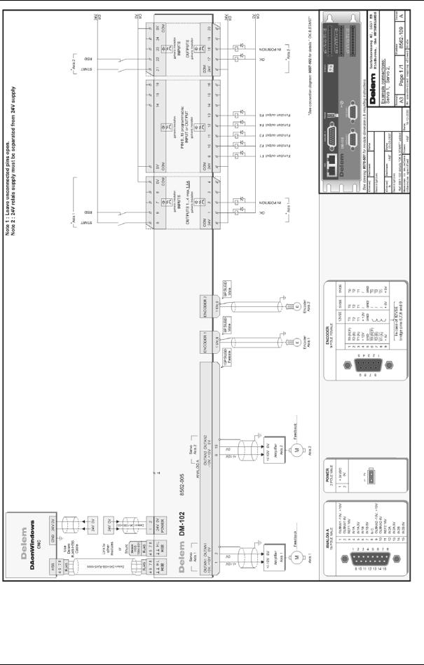
In this chapter the input and output signals of the Delem system are explained. See the installation manual of the control for the locations of the various connectors.
There is a strong relation between the Y-axis signals. This relation has been laid down in the timing diagram of the press cycle.
The timing diagram of the CNC-RDY signal has also been included. This signal indicates that the active bend program can be executed. The CNC-RDY signal depends on the status of the start button, the position of the Y-axis and the position of the X-axis.
1.2.Y-axis input signals
Symbol |
Function |
|
Opening command. This input must be active when the beam has |
|
to move in the opening direction (Y-axis status 6). |
|
Pressing command. This input must be active to move the press |
|
beam during the pressing phase (Y-axis status 3). This input must |
|
also stay active during the holding time (dwell time) at bend position |
|
and during decompression (Y-axis status 4 and 5). |
|
Fast closing command. This input must be active when the beam |
|
has to move with high speed in the closing direction (Y-axis status |
|
2). |
|
Manual. This input must be active when the beam must be moved |
|
manually with the handwheel. This is only possible when the control |
|
is in Manual mode and the beam is below the mute position. When |
|
this input is active this is displayed with the text 'adjust' in the lower |
|
right corner of the control screen. |
= |
Parallelism switch input. See description of Y-axis machine |
|
parameter 'parallelism switch'. |
V0908, 1.1
1.3.Y-axis output signals
Symbol |
Function |
|
Upper dead point. This output is active when the beam is at the |
|
programmed upper dead point or higher. |
ER |
End of decompression. This output becomes active after the beam |
|
has reached the bending position, the holding time has elapsed and |
|
the decompression distance is completed. It goes low again |
|
(inactive) when the opening input ( ) becomes active. |
|
Mute output. This output becomes active when the beam reached |
|
the muting point. This output stays active as long as the beam is |
|
below the mute position. |
|
CNC-started. This output is active when the start button on the DA- |
|
control is pressed. |
|
Special mute output / 2nd mute (for servo hydraulics). An optional |
|
mute output can be used to obtain that the beam will stop more |
|
accurate at the muting point. This feature can be useful when using |
|
servo hydraulics. The optional mute output will be active from a |
|
certain distance before the actual muting point. |
1.a
The braking ramp for stopping at the optional muting point is computed automatically by the control. The distance between the two muting points is programmable, the default value is 0 mm. This means that the two mute outputs become active at the same time.
V0908, 1.2

1.b
The point at which the optional mute output becomes active can also be shifted with an offset. This offset does not shift the computed braking point. It can be programmed with the parameter “Offset mute-2 output”. The default setting is 0.
Clamping (pinching) point output. This output becomes active when the beam reaches the clamping (pinching) point and stays active as long as the beam is below the clamping point.
Lower dead point output. This output becomes active at the end position of the press beam. This output is active during Y-axis status 4.
V0908, 1.3

1.4.X-axis signals
Symbol |
Function |
||
R-in |
R-axis positive input. This input must be active (+24V) to have the |
||
|
X-axis moving within the safety zone of the applied die. Otherwise |
||
|
the X-axis will not move within this zone and as a result the CNC- |
||
|
RDY output will never become active! |
||
|
When the R-axis is negative and the R-in input is active, the R-axis |
||
|
will first move to a positive position before the X-axis will move to a |
||
|
position within the safety zone. |
||
|
|
|
|
|
|
|
|
1.5.Axis signals
Symbol |
Function |
IP |
This output is active when the actual position value of the axis is |
|
within the in position tolerance range of the programmed position. |
|
This in position tolerance range can be set with the machine |
|
parameter ‘In position tolerance’ (parameter 12). |
START |
Input for an axis module, to signal that equipment is ready and the |
|
module can start positioning the axis. Can be used to monitor |
|
‘ready’ signal from a motor drive. |
RSD |
To take the reference marker from the encoder you can connect this |
|
input to the reference search direction switch. The reference search |
|
cycle is then as described at the machine parameter 17 (RSD- |
|
switch). The RSD input can also be taken from an End Of Travel |
|
switch. |
1.6.Various input and output signals
V0908, 1.4

|
|
|
|
|
|
|
|
|
|
|
Pump started. |
This input must be active to be able to press the start |
||
|
|
button on the DA-control. When this input is not active |
||
|
|
the start button will not be accepted and the control will |
||
|
|
display the message **machine not started**. |
||
T |
Tandem input. |
Tandem input for tandem or robot applications. See |
||
|
|
description of parameter 10 of the Y-axis parameters |
||
|
|
menu. For robot applications ask for the special robot |
||
|
|
function manual. |
||
C |
Cycle input. |
This input can be used to realise an external step |
||
|
|
change. This is done by programming the program |
||
|
|
specific CX-code parameter in the programs. |
||
|
CNC-START. |
The start command for the control. This output can only |
||
|
|
be active (start button on control) when the pump start |
||
|
|
input is active. |
||
FUNCTION OUTPUTS
F1, F2, F3, F4 These are general purpose outputs. When you use a motorized crowning unit then outputs F3 and F4 are not available, because they are reserved for crowning usage.
CNC-RDY |
This output can only become active when the control is in a |
|
|
production mode (automatic or step-by-step) and the following |
|
|
conditions are met: |
|
|
• |
the control has been started |
|
• |
the X-axis is in position |
|
• |
the beam is in the upper dead point (UDP signal is high) |
|
• |
the beam is not opening (the 'open' command is not active) |
|
• |
the sequencer signal C_HOLD_BEND is not active (optional, |
|
|
in case sequencer is modified) |
|
• |
the part support is down (optional, in case part support is |
|
|
installed) |
If the control is in manual mode the same conditions apply, except in manual mode the UDP signal is not necessary for the CNC-RDY.
OK |
Module |
Output signal from a module, to indicate that the module is |
|
initialisation |
properly initialised and is ready for action. Can be used as enable |
|
ready. |
signal to e.g. a motordrive. |
V0908, 1.5

1.c
V0908, 1.6

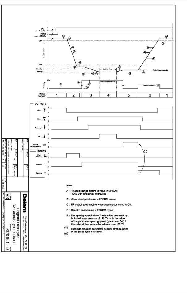
Explanation of CNC-RDY timing diagram
•Y-axis status. The Y-axis status is the number of the Y-axis control program, which depends on the Y-axis command inputs. The number is shown on the service row (when activated) in the header of the screen.
•Upper dead point. Y-axis output indicating that press beam is in the upper dead point position.
•X-axis at programmed position. This line shows the actual X-axis position. This is the same as the programmed position.
The start button must be pressed (1). When in this case the press beam is in the upper dead point (output active) and the X-axis reaches the programmed position (2) the CNC-RDY output becomes active (3). The CNC-RDY output stays active during fast closing of the press beam (4), pressing (5) (when no X-axis retraction is programmed), dwell time (6) and decompression (7).
The CNC-RDY becomes inactive after decompression of the beam (ER output active) at the step change position where the X-axis moves to the next programmed position. Depending on the Step change code this can take place at:
•end of decompression;
•mute (passed in opening direction);
•upper dead point.
The CNC-RDY signal becomes active again (9) when the X-axis is at its programmed position and the Y-axis is in the upper dead point.
CNC-RDY signal during pressing with retraction programmed
There are two situations during pressing with rectraction programmed (point 5 of CNC-RDY cyclus).
•The press beam does not wait at the pinching point for X-axis retraction to complete (“Wait for retract” is off). The CNC-RDY output stays active while the X-axis moves to the retract position.
•The press beam stops at the pinching point and waits until X-axis retraction is completed (“Wait for retract” is on). The CNC-RDY output stays active while the X-axis is moving to the retract position. The press beam moves again when the X-axis has reached the retract position.
There is also a third situation, but this is an option.
•The press beam stops at the pinching point and waits until the X-axis rectraction has been completed (“Wait for retract” is on). The CNC-RDY output is off while the X-axis is moving to the retract position. The CNC-RDY output becomes active again when the X- axis has reached the retract position.
V0908, 1.7
V0908, 1.8

V0908, 1.9
V0908, 1.10
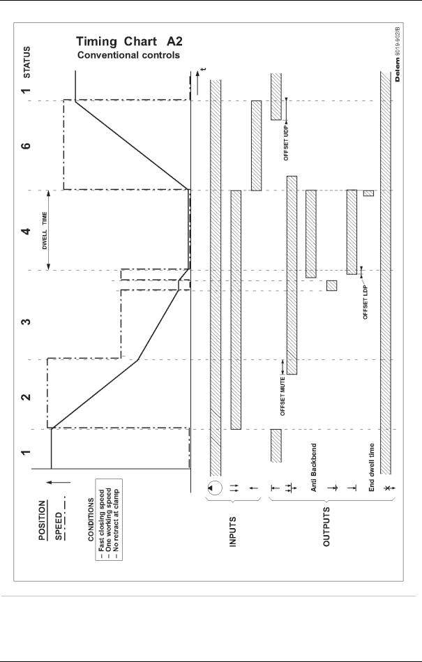
1.7.Conventional systems
Beside controls for synchronised Y-axis control, there are also Delem controls for conventional pressbrake machines. These controls have a different set of machine parameters for Y-axis control. The use of some parameters is related to the equipment that is installed.
1.d
•YM-axis
A mechanical stop for the Y-axis can be programmed as an auxiliary axis (axis type YM). This axis is controlled through the circuitry for Y1: the valve voltage output is used to control the motor, the encoder input for Y1. The YM axis is programmed as a standard auxiliary axis. On a DAonWindows control this auxiliary axis must be assigned to the Y-axis module. The parameters for this axis are all standard servo parameters, which are described in chapter 5.
•Pressbeam position feedback
A conventional pressbrake machine can be equipped with a linear or rotary encoder scale for position feedback.
If no linear scale is used, positioning of the pressbeam must be arranged externally. In that case, a switch for 'step change' must be installed to signal to the control that a bending has been carried out and the next step can be done. If the retract function is necessary in the machine, a switch for a 'retract request' must be installed.
If a linear scale for position feedback is installed, these switches are not necessary. The control can use the position information to generate a retract and a step change. Whether or not positioning control is used is programmed with the parameter "Encoder mounted".
See section 4.12 for more information about conventional parameters.
V0908, 1.11
V0908, 1.12

V0908, 1.13

V0908, 1.14

2.Machine parameters menu
2.1.Introduction
In this chapter the selection possibilities of the machine parameters menu are explained. The next selection possibilities are discussed:
•selection procedure machine parameters menu (section 2.2);
•a brief introduction on the Y-axis and general parameters (section 2.3);
•a brief introduction on the auxiliary axes (section 2.5);
•notes about module configuration and module software (section 2.6);
•machine parameters backup procedure (section 2.7);
•changing the access code (section 2.8);
•viewing options (section 2.9).
2.2.Selection procedure of machine parameters menu
The selection procedure of the machine parameters menu is the same for each type of control of the DAonWindows series.
Do the following to get access to the machine parameter menu:
•Select the programming mode.
•Enter 19 to select the machine parameter menu.
•Enter the access code.
•Press the enter key.
The default access code is 14753 for changing a basic set of machine parameters. The machine parameters followed by (2) cannot be changed with this code. When you want to change all the machine parameters you require the special factory code. This code may only be used by authorised people.
There is a third access code available, which gives access to a third level of parameters. Normally these parameters are set to factory default values and need no adjustment. In order to view and adjust these parameters, you need to enter the menu with a level 3 access code. You will see additional parameters, which are followed by a (3). This code may also be used only by authorised people.
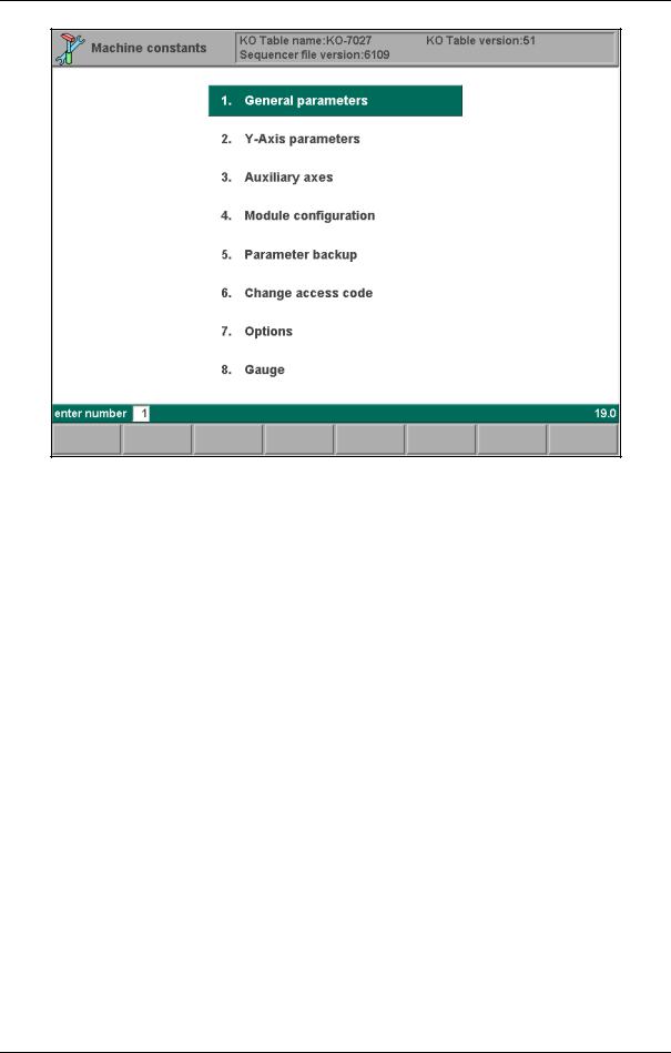
In the machine parameter main menu you also find the versions of the current KO-table and the sequencer file. For detailed information upon the KO-table and Sequencer file version please contact Delem.
In figure 2.a you see the main machine parameter menu of the control.
V0908, 2.1
2.a
2.3.General parameters
Behind this selection possibility you find the basic machine parameters to program the press brake specifications, such as dimensions. See chapter 3 for full explanation upon the parameters.
2.4.Y-axis parameters
Behind this selection possibility you find the machine parameters to control the Y-axis. See chapter 4 for full explanation upon the parameters.
2.5.Auxiliary Axes
Per type of control you can activate a number of auxiliary axes. An auxiliary axis is not active when it is disabled in the axes menu. The required function of an auxiliary axis is determined by the axis type.
Based on the available types the chapters 5 until 9 have been defined. In these chapters you find explanation on the parameters in more detail.
To install auxiliary axes, three steps must be taken:
•the modules must be selected through menu 4: 'module configuration',
•the configuration of backgauges must be programmed through menu 8: 'gauge',
•the intended axes must be programmed through menu 3: 'auxiliary axes'.
See chapter 5 about auxiliary axis configuration.
2.6.Module configuration
V0908, 2.2
This function serves to select the connected modules in the system and assign the proper axes to those modules.
Chapter 5 contains a detailed description of module configuration. This should be done first, because otherwise no axis can be controlled.
Modules can be upgraded with new software. The procedure to upgrade a module is explained in chapter 5.
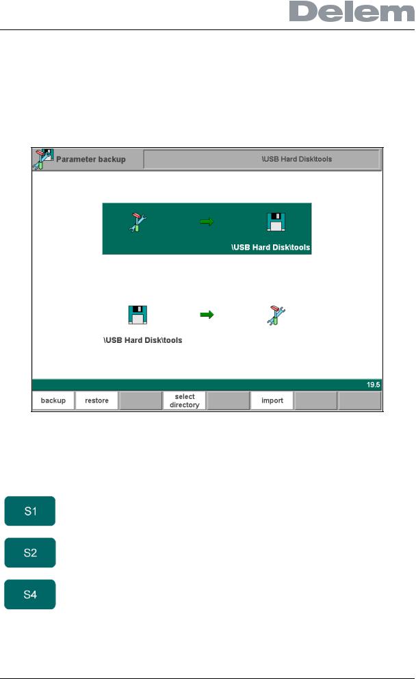
2.7.Machine parameters backup
2.b
It is very important to make a backup of the machine parameters each time they have been changed.
Function keys:
backup |
To save the machine parameters to back-up location. |
restore |
To load the machine parameters from back-up location. |
select |
To choose the location (directory) where parameters must |
directory |
be stored or read. |
V0908, 2.3

2.8.Changing the access code
You can change the access code of the machine parameters menu. The procedure is as follows:
•enter old code;
•enter new code;
•(re)enter new code;
press the enter key to accept the new value.
Without the correct access code it is impossible to enter the machine parameters menu. Therefore, be sure if you want to change the default access code (14753).
2.9.Options
The standard functionality of the Delem control can be expanded with extra options. A new option can only be used when the option has been enabled in the control. If you wish to activate an option, contact Delem to obtain an option voucher.
Installation of options is described in the installation manual of the DAonWindows controls. The options with the √ - sign are already enabled in the control and can be used.
2.c
V0908, 2.4
2.10.Gauge
In this menu the configuration of backgauges and auxiliary axes must be programmed. This programming facility offers a flexible way to describe the available backgauges and by which axes they are moved.
2.d
See chapter 5 for information about gauge programming.
2.11.Leaving the machine parameters menu
When leaving the machine parameters menu, beware of two things.
•The control checks if all programmed axes are properly assigned to DM modules. If this is not the case, the control issues a warning. See also chapter 5.
•If no machine parameter has been changed, the control returns to the main menu. If any parameter has been changed, the control will reset. If ‘enter’ is pressed while the cursor is on a machine parameter, the control will assume this parameter has been changed and will reset itself when the menu is left.
V0908, 2.5

V0908, 2.6
Loading...