

Page 1

Delem
DA-65W
Reference Manual
Operation
of Version V2
Manual version V0606
Page 2

PREFACE
This manual describes the operation of the Delem controller type DA-65W and is meant for
operators who are instructed for operation of the total machine.
Only authorised people should be able to create new or edit existing programs, as well as programming or editing of the tooldata. Therefore the controller has a keyswitch to prevent
uncontrolled programming. With the keyswitch in the off position the operator can only execute a selected program. The operator cannot change the parameters to wrong, unwanted values.
Version history
The control software is updated regularly to increase performance and add new functionality.
This manual is also updated as a result of changes in the control software. The following overview shows the relation between software and manual versions.
Software version Manual version Description
V2.1 V0404 first issue V2
V2.2 V1104 update
V2.3 V0505 update
V2.4 / V2.5 V0606 update
This manual is valid for software version 2.4 and 2.5.
V0606, 0.2
Page 3

Delem
Table of contents
1. Operation overview and general introduction . . . . . . . . . . . . . . . . 1.1
1.1. The control unit . . . . . . . . . . . . . . . . . . . . . . . . . . . . . . . . . . . . . . . . . . . . . . .1.1
1.2. Operation modes . . . . . . . . . . . . . . . . . . . . . . . . . . . . . . . . . . . . . . . . . . . . . .1.2
1.3. Frontpanel . . . . . . . . . . . . . . . . . . . . . . . . . . . . . . . . . . . . . . . . . . . . . . . . . . .1.3
1.4. Programming mode . . . . . . . . . . . . . . . . . . . . . . . . . . . . . . . . . . . . . . . . . . . .1.5
1.4.1. The main menu . . . . . . . . . . . . . . . . . . . . . . . . . . . . . . . . . . . . . . . . . . . . . .1.5
1.4.2. Help text . . . . . . . . . . . . . . . . . . . . . . . . . . . . . . . . . . . . . . . . . . . . . . . . . . .1.7
1.4.3. Listbox functionality . . . . . . . . . . . . . . . . . . . . . . . . . . . . . . . . . . . . . . . . .1.9
1.5. Graphical programming . . . . . . . . . . . . . . . . . . . . . . . . . . . . . . . . . . . . . . .1.10
1.5.1. Control keys . . . . . . . . . . . . . . . . . . . . . . . . . . . . . . . . . . . . . . . . . . . . . . .1.11
1.6. Network . . . . . . . . . . . . . . . . . . . . . . . . . . . . . . . . . . . . . . . . . . . . . . . . . . . .1.12
1.7. Software versions . . . . . . . . . . . . . . . . . . . . . . . . . . . . . . . . . . . . . . . . . . . .1.13
1.8. Delem Limited warranty . . . . . . . . . . . . . . . . . . . . . . . . . . . . . . . . . . . . . . .1.14
2. Product drawing/Product edit for 2-dimensional products . . . . . . 2.1
2.1. Introduction . . . . . . . . . . . . . . . . . . . . . . . . . . . . . . . . . . . . . . . . . . . . . . . . . .2.1
2.2. Delete an angle/line or insert an angle . . . . . . . . . . . . . . . . . . . . . . . . . . . . .2.6
2.3. Precision selection . . . . . . . . . . . . . . . . . . . . . . . . . . . . . . . . . . . . . . . . . . . . .2.6
2.4. Large Radius: Bumping . . . . . . . . . . . . . . . . . . . . . . . . . . . . . . . . . . . . . . . .2.8
2.5. Assignments . . . . . . . . . . . . . . . . . . . . . . . . . . . . . . . . . . . . . . . . . . . . . . . . .2.9
• Parameter explanation . . . . . . . . . . . . . . . . . . . . . . . . . . . . . . . . . . . . . .2.11
• Parameter explanation . . . . . . . . . . . . . . . . . . . . . . . . . . . . . . . . . . . . . .2.12
• Parameter explanation . . . . . . . . . . . . . . . . . . . . . . . . . . . . . . . . . . . . . .2.15
2.6. Bend sequence . . . . . . . . . . . . . . . . . . . . . . . . . . . . . . . . . . . . . . . . . . . . . . .2.16
• Restoring a bend sequence . . . . . . . . . . . . . . . . . . . . . . . . . . . . . . . . . .2.22
• Minimum bending length . . . . . . . . . . . . . . . . . . . . . . . . . . . . . . . . . . .2.23
• Machine/Tool selection . . . . . . . . . . . . . . . . . . . . . . . . . . . . . . . . . . . . .2.24
• Turn indication . . . . . . . . . . . . . . . . . . . . . . . . . . . . . . . . . . . . . . . . . . .2.24
• Production time . . . . . . . . . . . . . . . . . . . . . . . . . . . . . . . . . . . . . . . . . . .2.25
• Screen data . . . . . . . . . . . . . . . . . . . . . . . . . . . . . . . . . . . . . . . . . . . . . .2.25
• Function- and control keys summary . . . . . . . . . . . . . . . . . . . . . . . . . .2.26
• Bend sequence computation . . . . . . . . . . . . . . . . . . . . . . . . . . . . . . . . . .2.27
• Store . . . . . . . . . . . . . . . . . . . . . . . . . . . . . . . . . . . . . . . . . . . . . . . . . . .2.28
2.7. Variants programming . . . . . . . . . . . . . . . . . . . . . . . . . . . . . . . . . . . . . . . .2.28
4. Data preparation/Data edit . . . . . . . . . . . . . . . . . . . . . . . . . . . . . . . . 4.1
4.1. Introduction . . . . . . . . . . . . . . . . . . . . . . . . . . . . . . . . . . . . . . . . . . . . . . . . . .4.1
• Edit notes . . . . . . . . . . . . . . . . . . . . . . . . . . . . . . . . . . . . . . . . . . . . . . . . .4.2
• Parameter explanation . . . . . . . . . . . . . . . . . . . . . . . . . . . . . . . . . . . . . . .4.3
• Connecting CNC programs . . . . . . . . . . . . . . . . . . . . . . . . . . . . . . . . . . .4.4
4.2. Bend programming . . . . . . . . . . . . . . . . . . . . . . . . . . . . . . . . . . . . . . . . . . . .4.5
• Axis functions . . . . . . . . . . . . . . . . . . . . . . . . . . . . . . . . . . . . . . . . . . . . .4.6
• Parameter explanation . . . . . . . . . . . . . . . . . . . . . . . . . . . . . . . . . . . . . . .4.7
• Parameter explication (second page) . . . . . . . . . . . . . . . . . . . . . . . . . . .4.11
V0606, 0.3
Page 4

• Slave axes . . . . . . . . . . . . . . . . . . . . . . . . . . . . . . . . . . . . . . . . . . . . . . . 4.16
• List of bendings of the prepared program . . . . . . . . . . . . . . . . . . . . . . . 4.17
• Ending data preparation/data editing . . . . . . . . . . . . . . . . . . . . . . . . . . 4.19
4.3. Special edit function . . . . . . . . . . . . . . . . . . . . . . . . . . . . . . . . . . . . . . . . . . 4.20
4.4. Edit notes . . . . . . . . . . . . . . . . . . . . . . . . . . . . . . . . . . . . . . . . . . . . . . . . . . 4.20
5. Product selection . . . . . . . . . . . . . . . . . . . . . . . . . . . . . . . . . . . . . . . . 5.1
5.1. Introduction . . . . . . . . . . . . . . . . . . . . . . . . . . . . . . . . . . . . . . . . . . . . . . . . . 5.1
• Expanded directory . . . . . . . . . . . . . . . . . . . . . . . . . . . . . . . . . . . . . . . . . 5.4
• Search function . . . . . . . . . . . . . . . . . . . . . . . . . . . . . . . . . . . . . . . . . . . . 5.4
5.2. Directories . . . . . . . . . . . . . . . . . . . . . . . . . . . . . . . . . . . . . . . . . . . . . . . . . . 5.6
6. Programming of tools . . . . . . . . . . . . . . . . . . . . . . . . . . . . . . . . . . . . 6.1
6.1. Introduction . . . . . . . . . . . . . . . . . . . . . . . . . . . . . . . . . . . . . . . . . . . . . . . . . 6.1
6.2. Programming of Punches . . . . . . . . . . . . . . . . . . . . . . . . . . . . . . . . . . . . . . . 6.1
6.2.1. The punch menu . . . . . . . . . . . . . . . . . . . . . . . . . . . . . . . . . . . . . . . . . . . . 6.1
• Graphical directory . . . . . . . . . . . . . . . . . . . . . . . . . . . . . . . . . . . . . . . . . 6.3
• Edit punch drawing . . . . . . . . . . . . . . . . . . . . . . . . . . . . . . . . . . . . . . . . . 6.4
• Drawing orientation of the punch on the screen . . . . . . . . . . . . . . . . . . . 6.5
6.2.2. Specific Punch Data . . . . . . . . . . . . . . . . . . . . . . . . . . . . . . . . . . . . . . . . . 6.5
6.3. Programming of bottom dies . . . . . . . . . . . . . . . . . . . . . . . . . . . . . . . . . . . . 6.9
6.3.1. The die menu . . . . . . . . . . . . . . . . . . . . . . . . . . . . . . . . . . . . . . . . . . . . . . . 6.9
• Graphical directory dies . . . . . . . . . . . . . . . . . . . . . . . . . . . . . . . . . . . . . 6.11
• Edit die drawing . . . . . . . . . . . . . . . . . . . . . . . . . . . . . . . . . . . . . . . . . . . 6.11
6.3.2. Specific die data . . . . . . . . . . . . . . . . . . . . . . . . . . . . . . . . . . . . . . . . . . . 6.13
6.4. Machine upper side and lower side . . . . . . . . . . . . . . . . . . . . . . . . . . . . . . 6.16
6.5. Saving/loading of tools . . . . . . . . . . . . . . . . . . . . . . . . . . . . . . . . . . . . . . . . 6.19
7. Products and tools back-up . . . . . . . . . . . . . . . . . . . . . . . . . . . . . . . . 7.1
7.1. Introduction . . . . . . . . . . . . . . . . . . . . . . . . . . . . . . . . . . . . . . . . . . . . . . . . . 7.1
7.2. Directory navigation . . . . . . . . . . . . . . . . . . . . . . . . . . . . . . . . . . . . . . . . . . . 7.2
7.3. Product backup . . . . . . . . . . . . . . . . . . . . . . . . . . . . . . . . . . . . . . . . . . . . . . . 7.3
7.4. Tool back-up . . . . . . . . . . . . . . . . . . . . . . . . . . . . . . . . . . . . . . . . . . . . . . . . . 7.5
8. Program Constants . . . . . . . . . . . . . . . . . . . . . . . . . . . . . . . . . . . . . . 8.1
8.1. Introduction . . . . . . . . . . . . . . . . . . . . . . . . . . . . . . . . . . . . . . . . . . . . . . . . . 8.1
8.2. General . . . . . . . . . . . . . . . . . . . . . . . . . . . . . . . . . . . . . . . . . . . . . . . . . . . . . 8.1
8.3. Materials . . . . . . . . . . . . . . . . . . . . . . . . . . . . . . . . . . . . . . . . . . . . . . . . . . . . 8.4
8.4. Program settings . . . . . . . . . . . . . . . . . . . . . . . . . . . . . . . . . . . . . . . . . . . . . . 8.5
8.5. Computation settings . . . . . . . . . . . . . . . . . . . . . . . . . . . . . . . . . . . . . . . . . . 8.8
8.6. Production settings . . . . . . . . . . . . . . . . . . . . . . . . . . . . . . . . . . . . . . . . . . . 8.10
8.7. Serial ports . . . . . . . . . . . . . . . . . . . . . . . . . . . . . . . . . . . . . . . . . . . . . . . . . 8.14
8.8. Production time calculation . . . . . . . . . . . . . . . . . . . . . . . . . . . . . . . . . . . . 8.15
8.9. Backgauge dimensions . . . . . . . . . . . . . . . . . . . . . . . . . . . . . . . . . . . . . . . 8.16
8.10. Part support dimensions . . . . . . . . . . . . . . . . . . . . . . . . . . . . . . . . . . . . . . 8.18
8.11. Event logging . . . . . . . . . . . . . . . . . . . . . . . . . . . . . . . . . . . . . . . . . . . . . . 8.20
8.11.1. Parameters . . . . . . . . . . . . . . . . . . . . . . . . . . . . . . . . . . . . . . . . . . . . . . . 8.20
8.11.2. Explanation . . . . . . . . . . . . . . . . . . . . . . . . . . . . . . . . . . . . . . . . . . . . . . 8.22
V0606, 0.4
Page 5

Delem
8.12. Maintenance . . . . . . . . . . . . . . . . . . . . . . . . . . . . . . . . . . . . . . . . . . . . . . .8.24
9. Manual mode . . . . . . . . . . . . . . . . . . . . . . . . . . . . . . . . . . . . . . . . . . . 9.1
9.1. Introduction . . . . . . . . . . . . . . . . . . . . . . . . . . . . . . . . . . . . . . . . . . . . . . . . . .9.1
• Parameter Explanation . . . . . . . . . . . . . . . . . . . . . . . . . . . . . . . . . . . . . . .9.3
• Zoom function . . . . . . . . . . . . . . . . . . . . . . . . . . . . . . . . . . . . . . . . . . . . .9.6
9.2. Manual operation of the axes . . . . . . . . . . . . . . . . . . . . . . . . . . . . . . . . . . . .9.7
• To teach . . . . . . . . . . . . . . . . . . . . . . . . . . . . . . . . . . . . . . . . . . . . . . . . . .9.8
10. Automatic / step by step mode . . . . . . . . . . . . . . . . . . . . . . . . . . . 10.1
10.1. Introduction . . . . . . . . . . . . . . . . . . . . . . . . . . . . . . . . . . . . . . . . . . . . . . . .10.1
• Parameters . . . . . . . . . . . . . . . . . . . . . . . . . . . . . . . . . . . . . . . . . . . . . . .10.3
• Corrections . . . . . . . . . . . . . . . . . . . . . . . . . . . . . . . . . . . . . . . . . . . . . . .10.4
• Functions screen . . . . . . . . . . . . . . . . . . . . . . . . . . . . . . . . . . . . . . . . . . .10.6
• Graphical visualisation . . . . . . . . . . . . . . . . . . . . . . . . . . . . . . . . . . . . . .10.6
• Zoomed values . . . . . . . . . . . . . . . . . . . . . . . . . . . . . . . . . . . . . . . . . . . .10.7
• Bumping correction . . . . . . . . . . . . . . . . . . . . . . . . . . . . . . . . . . . . . . . .10.8
• Manual positioning . . . . . . . . . . . . . . . . . . . . . . . . . . . . . . . . . . . . . . . . .10.9
10.2. Step mode . . . . . . . . . . . . . . . . . . . . . . . . . . . . . . . . . . . . . . . . . . . . . . . .10.10
A. Parameter index . . . . . . . . . . . . . . . . . . . . . . . . . . . . . . . . . . . . . . . . A.1
V0606, 0.5
Page 6

V0606, 0.6
Page 7
1. Operation overview and general introduction
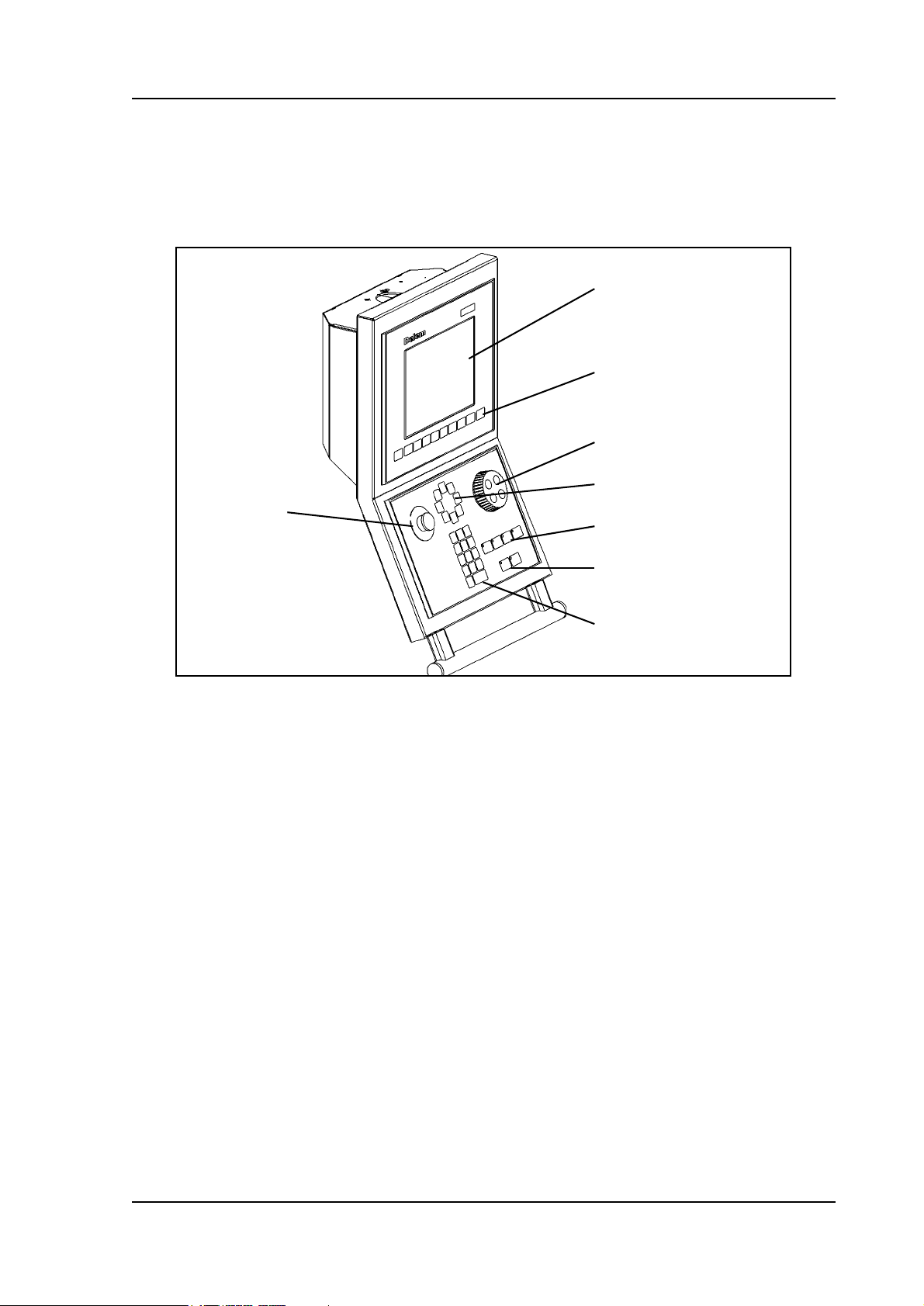
1.1. The control unit
The control looks as follows:
Delem
screen
function keys
wheel
em. stop
button
1.a
The precise outfit of your control may vary.
Operation of the control is done with the various keys on the front panel. A description of all
keys and their functions is given in the next section.
Beside the front panel keys, a built-in touchpad or external USB mouse can be used as a pointing device to select menu items, parameters or softkeys. It depends on your configuration
whether such a device is available. In this manual the phrase ‘mouse’ is used to describe any of
these possible pointing devices.
arrows
mode keys
start/stop
num. keys
V0606, 1.1
Page 8
1.2. Operation modes
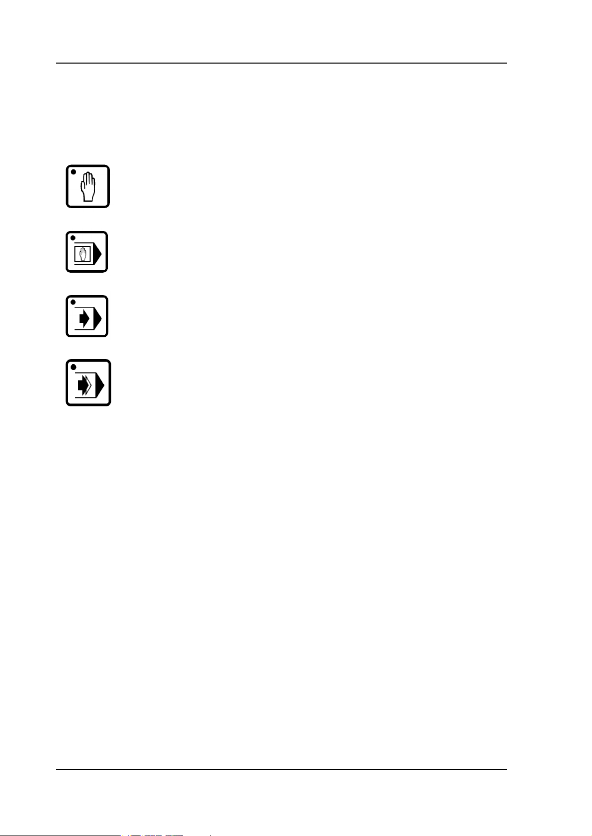
The control has the 4 following modes:
Manual mode In this mode it is possible to program all parameters of
just one bending. After pushing the start button all parameters are active and the backgauge will go into position. It
is also possible to move the axes manually.
Programming
mode
Automatic
mode
Step by step
mode
Each mode can be selected by pressing the relevant push button. A LED in the push button
indicates whether or not this mode is active.
In this mode bend programs can be made or edited and
also be written to or read from disk.
The selected program can be executed automatically.
The selected program can be executed bend by bend.
V0606, 1.2
Page 9
Delem
1.3. Frontpanel
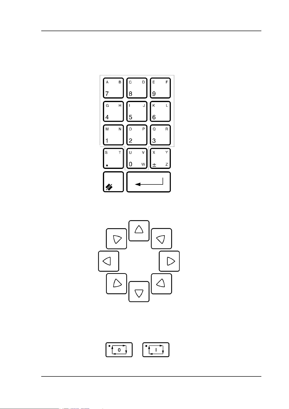
The frontpanel, besides the 4 operation mode buttons, consists of the following items :
Keyboard:
decimal point
clear key: Clearance
of the input data field
in the bottom left corner on the monitor
screen
10 numerical keys (0-
9) incl. alphanumeric
input
plus/minus toggle
enter key, to confirm a
programmed value
Cursor path control:
Stop button Start button
V0606, 1.3
Page 10
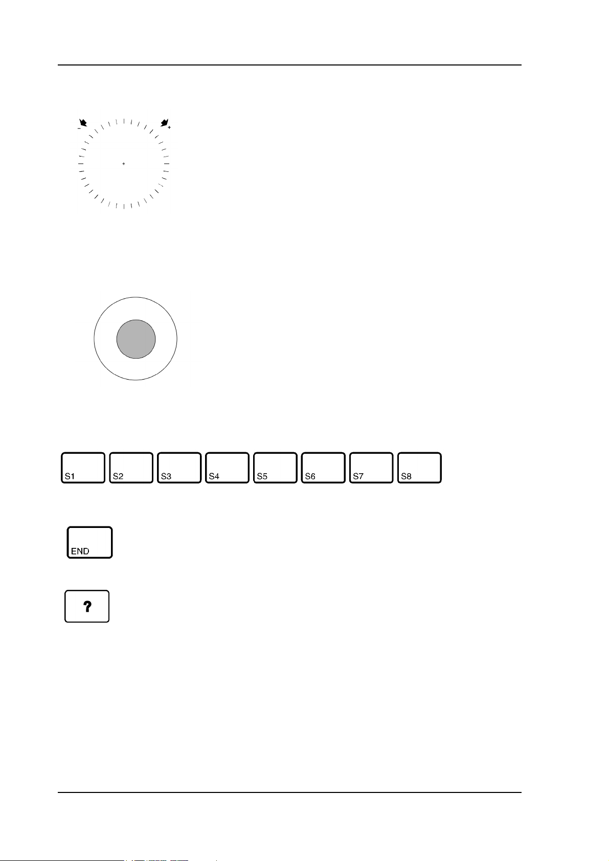
Handwheel; Manual control of any axis (Y + backgauge
axes)
Emergency stop button, to be implemented by machine
manufacturer.
Softkeys; The function of these keys is stated at the bottom side of the monitor screen.
End of menu program.
It is also possible to leave a menu by pressing <ESC> on
an external keyboard or clicking with the mouse on the
menu symbol in the upper left corner.
On the screen pages where you find the "?" symbol you
can press the "?" to get an explanation of the respective
function or parameter to program.
V0606, 1.4
Page 11
1.4. Programming mode
1.4.1. The main menu
Delem
Programming
mode
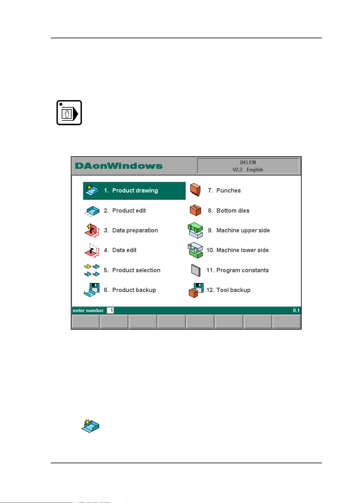
The main menu in programming mode looks as follows:
Select the programming mode.
1.b
Each of these menu items can be selected in several ways:
- enter the menu number and press ENTER
- use the arrow keys to scroll to the desired menu item and press ENTER
- click with the mouse once on the desired menu item
Explanation of menu items:
To draw your product on the screen and compute the
1
bendsequence (graphical).
V0606, 1.5
Page 12
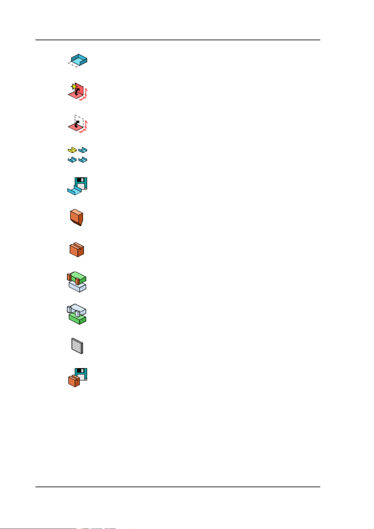
To edit your product drawing and compute the bendse-
2
3
4
5
6
7
quence (graphical).
Creation of a new CNC-program by data entry (numerical).
To edit an existing CNC-program by data entry (numerical).
To select a program out of the product library.
Write programs to or read programs from a back-up
medium.
To program the dimensions of the upper tools.
8
9
10
11
12
To program the dimensions of the under tools.
To program the dimensions of the upper side of your
machine.
To program the dimensions of your machine table.
To program specific programming data.
Write or read tooling data and machine shapes to or from
a back-up medium.
V0606, 1.6
Page 13
Delem
1.4.2. Help text
This control is equipped with an on-line Help function. This help text is available when the
question mark ‘<?>’ appears on the screen (lower right corner).
1.c
To activate a help window for a parameter:
- press the question mark key (‘?’) on the frontpanel or
- click with the mouse on the help symbol.
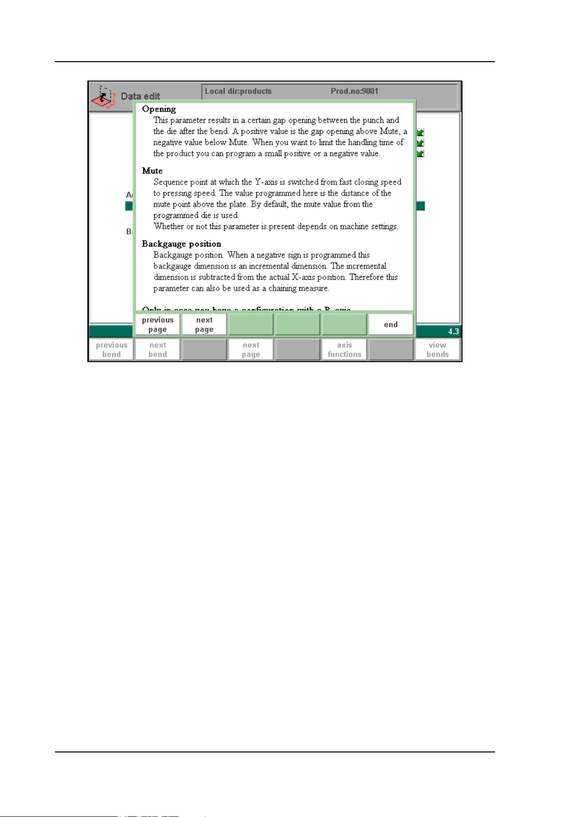
A pop-up window appears with information on the active parameter.
V0606, 1.7
Page 14
1.d
This Help window contains the same information as the Operation manual.
The help window can be used as follows:
Use the arrow keys (up/down) to browse through the help text or use the function keys 'previous page' and 'next page'.
Press the function key 'end' or the END key to close the Help window.
V0606, 1.8
Page 15
Delem
1.4.3. Listbox functionality
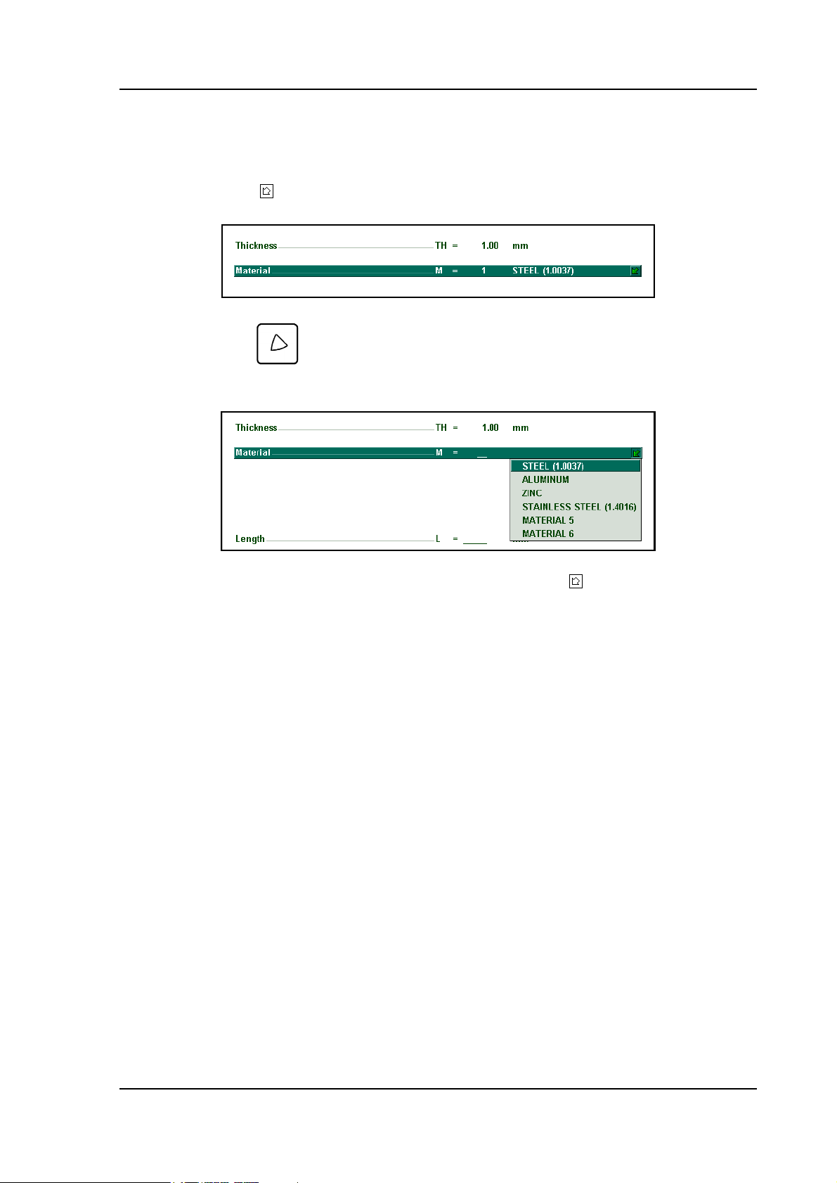
Several parameters on the control have a limited number of possible values. Beside such
parameters, the sign appears.
This means that the key can be pressed to get a listbox with possible values of this
parameter.
This listbox can also be opened by clicking with the mouse on the symbol.
V0606, 1.9
Page 16

1.5. Graphical programming
From the main menu you can select one of the programming possibilities.
In order to design or edit a new product, the graphical programming facility is present.
This facility is a complete product design tool that allows you to draw the profile of your product. It consists of a machine-and tool-library which allows you fast automatic, interactive or
manual bending sequence computations with display of possible product/tool/machine collisions and developed length.
The graphic design tool provides a way of selecting the most optimal bend sequence for a
product, keeping in mind the minimum production time and manipulation possibilities of the
product.
Features of the design tool
- Graphical design of product shapes in 2D and 3D (if available)
- Auto scaling
- Horizontal and vertical projected dimensions can be entered
- Blank length computation
- Real scale tool design
- 10 different upper side shapes and 10 different under side shapes (tables)
- Changing of lengths and angles
- Bumping (big radius)
- Adding or deleting of bends
- Existing products can be copied, changed and stored as a new product
- Production time indication
- Closing dimension or highest precision tolerance selection
- Connecting 2D programs for 3D-production
Bending sequence computation
- Fast automatic computation for minimum production time
- Interactive bending sequence fixation
- Manual bending sequence fixation
- Collision visualisation of product with tools and machine
- Free tool and machine shape selections
- Assignments of turn times, backgauge speed etc.
- Bending sequence simulation
- Free selection of R-axis position
Postprocessing of drawings
The postprocess facility computes:
- Fully automatic
- Machine adjustment such as:
• Y-axis position
• Decompression
• X-axis position
• X-axis retract
• Y-opening
• R-axes
V0606, 1.10
Page 17
Delem
• Z-axes
Axes according to the machine configuration
The 2D-programming will be explained in chapter 2.
The 3D-programming (if available) will be explained in chapter 3.
1.5.1. Control keys
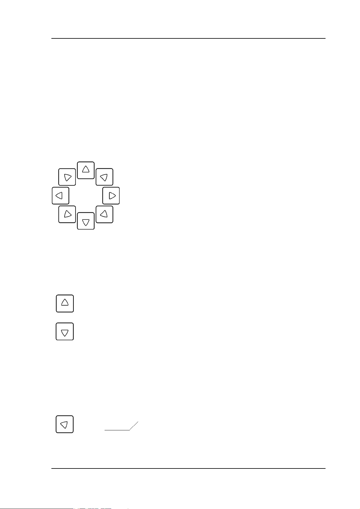
The drawing software uses several function keys on the front panel. The function depends on
the type of control (2D or 3D functionality)
- S1 thru 8
- Drawing cursor control with:
- Zoom function:
At bendsimulation overview in case of 2D-products (bendsequence menu and automatic
mode):
Enlargement
Reducement
- Drawing cursor control for 2D-products
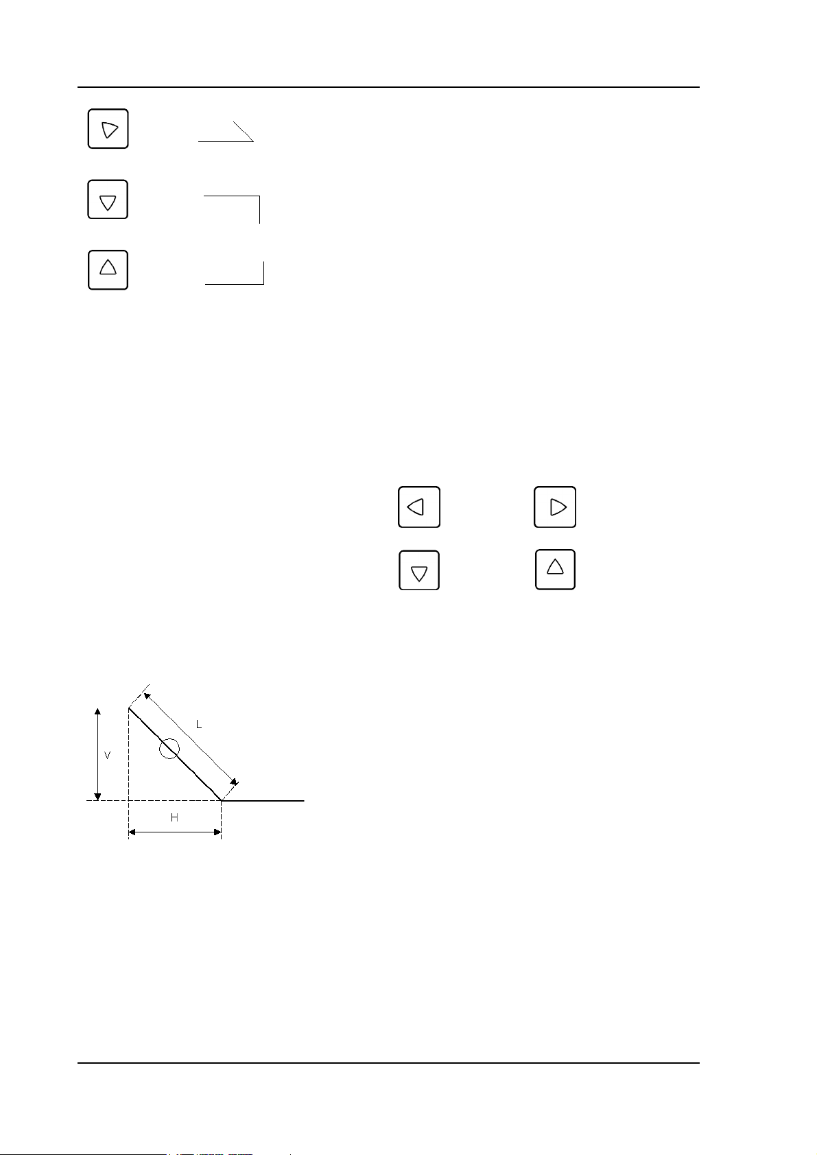
In case you are drawing the profile of your product or tools the cursor keys can be used to give
directly multiples 45 degree angles. e.g.:
a = 135°
V0606, 1.11
Page 18
a = 45°
a = -90°
a = 90°
- Horizontal or vertical projections for 2D-products
After you entered the length of the line interval you can specify if this line interval is either the
nominal length, horizontal or vertical projection. The given length dimension in the enter field
is the line length L if the drawing cursor is in the concerning line.
Horizontal projection with or key
Vertical projection with or key
L is normal entered line length
V is vertical projected line length
H is horizontal projected line length
It will be noted on the screen if projection is not possible.
1.6. Network
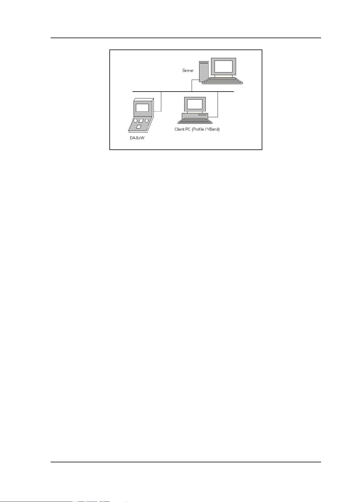
The CNC control is equipped with a network interface. The network function offers the operators the possibility to import product files directly from the network directories or to export the
finished product files to the required network directory.
V0606, 1.12
Page 19
1.e
Chapter 7 contains more information about networking possibilities.
1.7. Software versions
Delem
The version of the software in your control is displayed at the upper side of the menu screen in
the programming mode.
Example of version number:
V 2.1
V stands for version
2 is version number
1 is version level
The version number is increased when new features are added to the software, the level number is increased when minor corrections are needed in the existing version number.
V0606, 1.13
Page 20

1.8. Delem Limited warranty
• This manual does not entitle you to any rights. Delem reserves the right to change this
manual without prior warning.
• All rights reserved. The copyright is held by Delem. No part of this publication may be
copied or reproduced without written permission from Delem BV.
V0606, 1.14
Page 21
Delem
2. Product drawing/Product edit for 2-dimensional products
2.1. Introduction
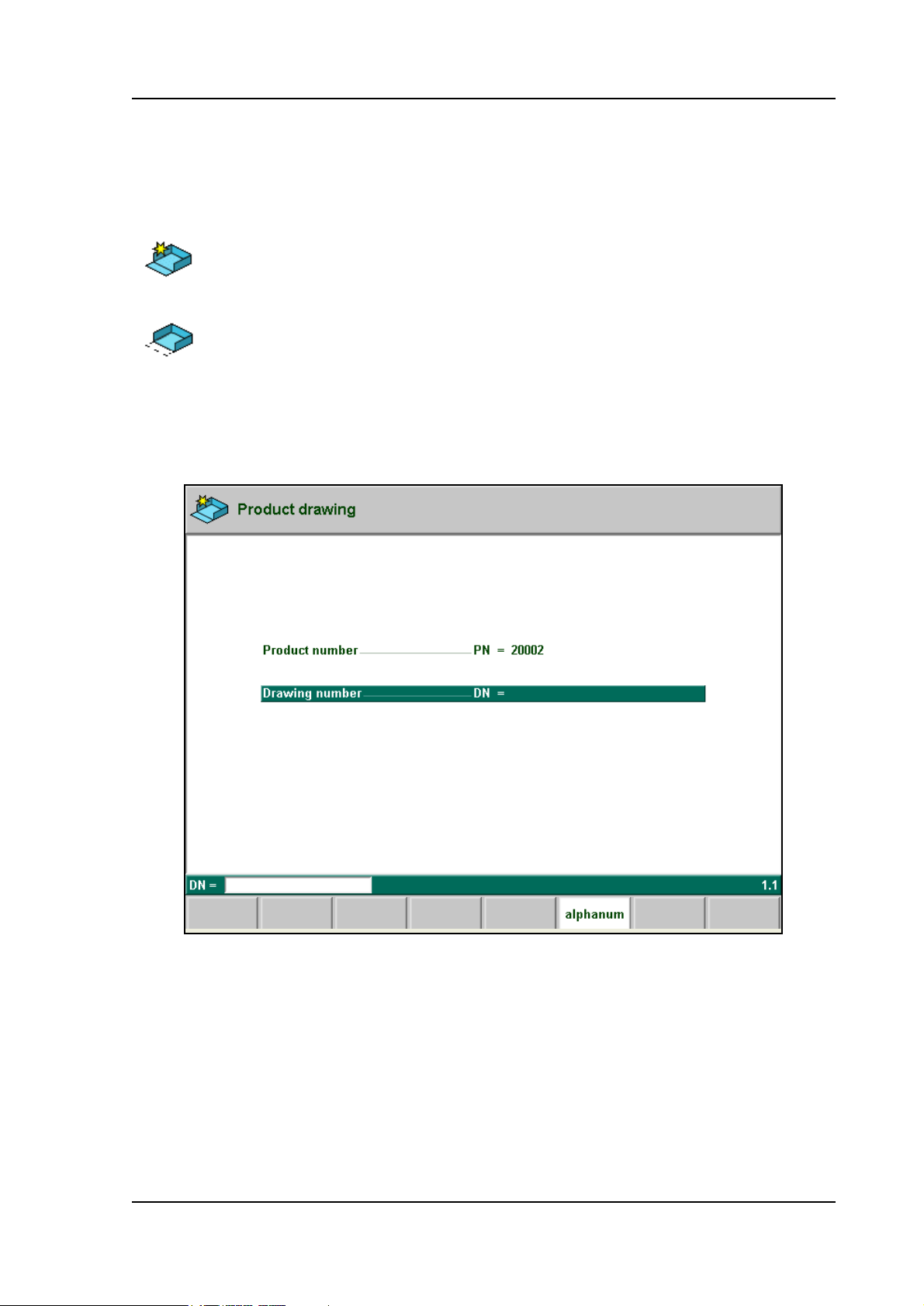
To start a new product drawing, choose product drawing in the
main menu.
To edit an existing product drawing, choose product edit in the
main menu.
On this page you have to enter first the product number and then the drawing number. The
drawing number may also contain alphanumeric characters, which can be entered with the help
of the function key ‘alphanum’ (S6).
2.a
Product number . . . . . . . . . . . . . . . . . . . . . . . . . . . . . . . . . . . . . . . . . . .PN
A unique number to identify a product program. The maximum length is 7 digits.
Drawing number. . . . . . . . . . . . . . . . . . . . . . . . . . . . . . . . . . . . . . . . . . .DN
A name or description of this program. The maximum length is 20 characters.
If an existing product number is entered, a warning appears that this product already exists.
You are asked whether to replace that existing product with the new product or not. If you
choose ‘yes', the existing product is erased. If you choose ‘no', you must enter a new number.
V0606, 2.1
Page 22
The "±" key prompts a "-" character and the "." key prompts a "/" character in the drawing
number.
If 3D is available on the control, it is first required to confirm whether the drawing programming will be effectuated in 2D or 3D. 3D drawing is explained in chapter 3.
After finishing this input you have to enter specific product data. Then you can start drawing
the product.
In the edit mode you also have the possibility to make a copy of the active product. A special
function key ‘copy product’ appears.
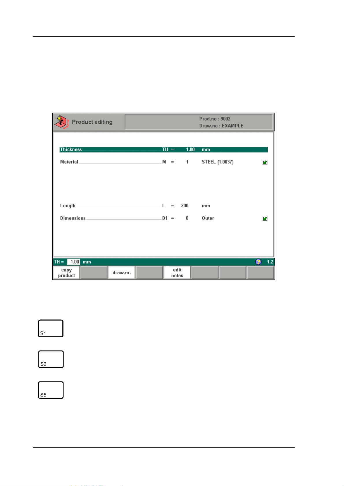
2.b
Function keys
copy product
draw. nr. Go to the screen with product number and drawing num-
edit notes Open a window with notes about the current product.
When the function key ‘edit notes’ has been pressed, a new window appears in which you can
edit the text about the current product. See the chapter ‘Data preparation/Data Edit’ for more
Copy the current product. When pressed, you must enter
a new product number for the new copy.
ber, in order to edit the drawing number.
V0606, 2.2
Page 23
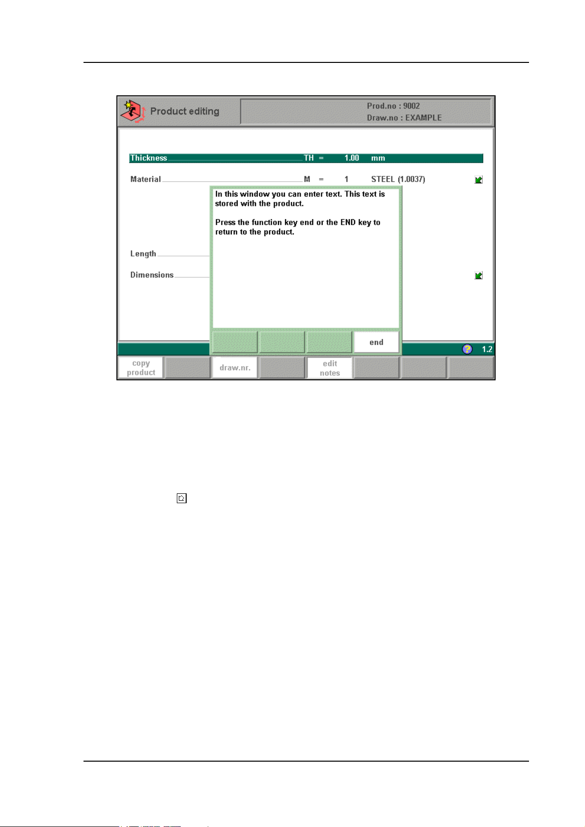
information about product notes.
Delem
2.c
Thickness . . . . . . . . . . . . . . . . . . . . . . . . . . . . . . . . . . . . . . . . . . . . . . . . .TH=
Thickness of the material of the plate in millimeters (mm).
Material . . . . . . . . . . . . . . . . . . . . . . . . . . . . . . . . . . . . . . . . . . . . . . . . . .M=
Selection of the material type. The control contains 4 preprogrammed materials. In total,
99 materials can be programmed on the control. See chapter 8 how to program materials.
Press the key to select the required setting.
Length . . . . . . . . . . . . . . . . . . . . . . . . . . . . . . . . . . . . . . . . . . . . . . . . . . .L=
The Z-length of the plate in millimeters (mm).
Dimensions . . . . . . . . . . . . . . . . . . . . . . . . . . . . . . . . . . . . . . . . . . . . . . .D1=
Determine the use of the outside(A) or the inside(B) dimensions in the product drawing.
V0606, 2.3
Page 24
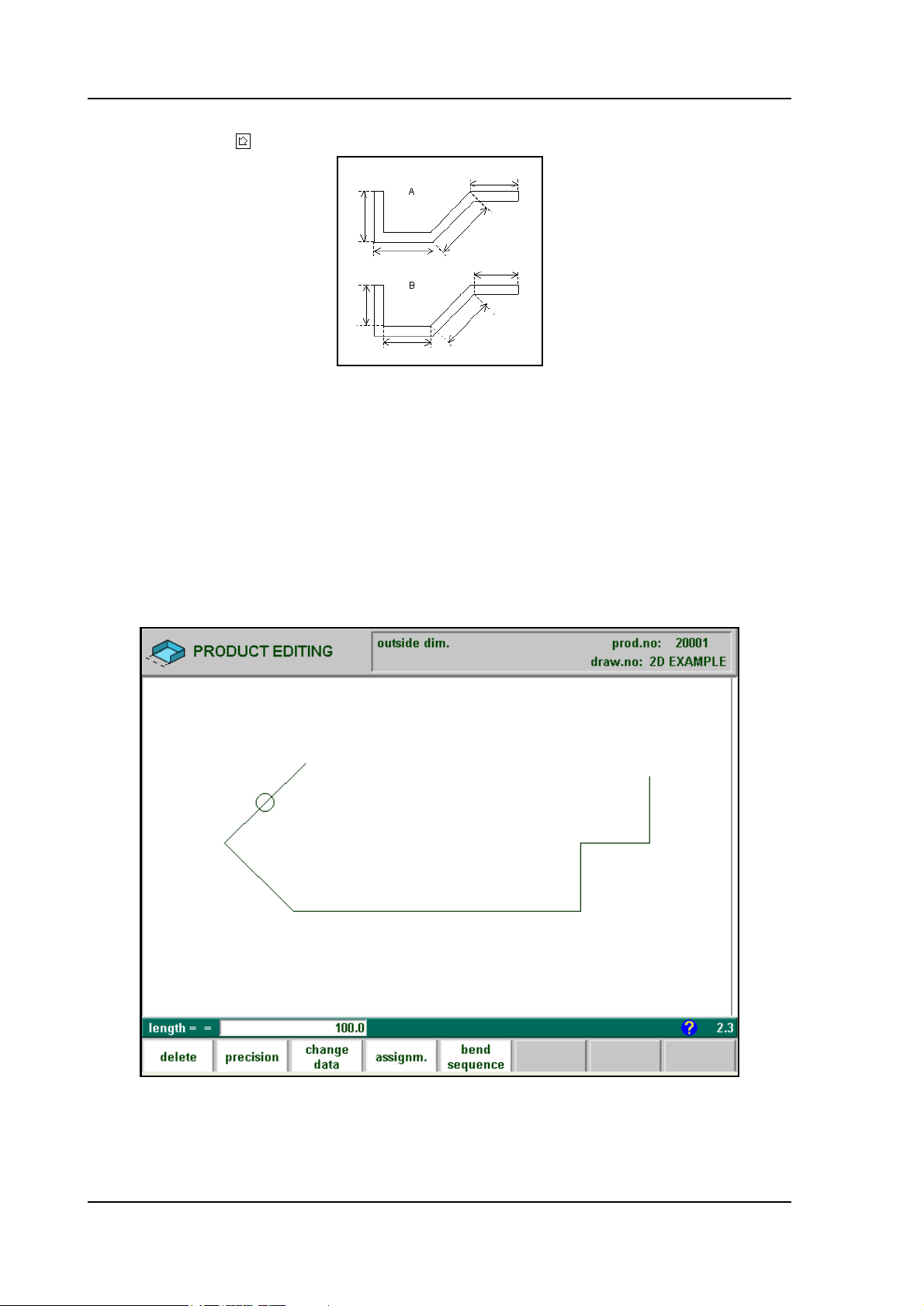
Figure 2.d gives the definition of both the dimensions.
Press the key to select the required setting.
2.d
After entering the general product data the drawing screen appears. In the upper information
row you will find the information about product number, drawing number and inside/outside
dimensions selection.
You create now the bending profile of the product. First you enter the value of the basic length
of the product. Then you enter the angle of the next side followed by the length of that side.
This procedure continues until the product has the desired profile. A circle indicates the actual
position. With the cursor control keys you move this circle to an other position (angle or
length). During the drawing of the profile of the product the graphical software always displays the product at relative scale.
2.e
For creating the product drawing you have to enter the length of a line and the angle to bend or
you can use the cursorkeys for angles of multiple 45 degrees.
V0606, 2.4
Page 25

Delem
In ‘product drawing’ or ‘product edit’ of a 2D product you can program up to a maximal of 99
bendings per product (graphical programming).
Function keys:
insert /
delete
precision To define selected line segment, with round cursor, for
bumping Bumping: when the cursor is on an angle you can create
change
data
assignments
bend
sequence
Delete an angle/line or insert an angle, depending on the
drawing cursor position (section 2.2).
high precision or if it is to be a "closing" dimension (section 2.3).
an angle with a big radius (section 2.4).
To page with product data.
To select assignments for bending sequence computations
(section 2.5).
Program bend sequence (section 2.6).
Return to main menu
These functions will be explained in the sections as indicated in the abovementioned overview.
V0606, 2.5
Page 26
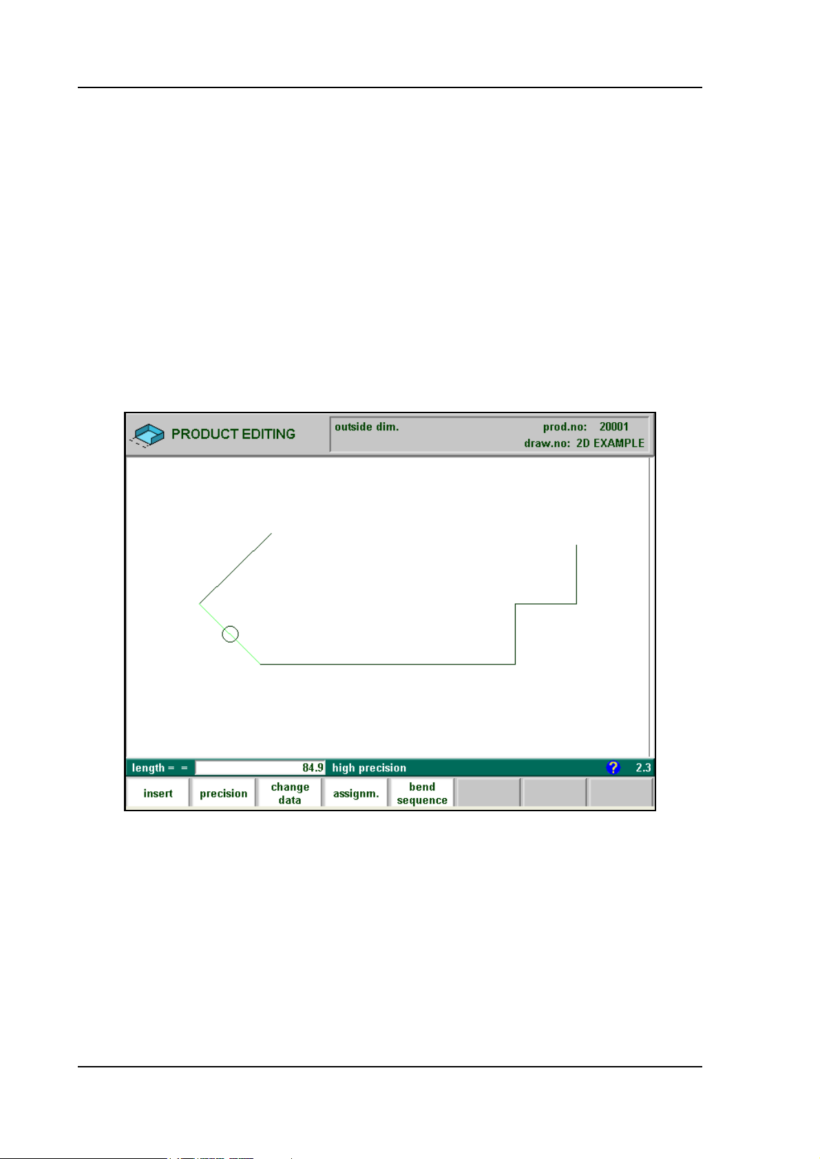
2.2. Delete an angle/line or insert an angle
The function of softkey (S1) depends on the position of the drawing cursor.
- If the cursor is within a line segment, it is possible to insert a new angle to bend, in combination with the enter key.
- If the cursor is positioned on a bend, it is possible to delete that bend.
- If the cursor is at an end line of the product, the line can be deleted.
2.3. Precision selection
When the drawing cursor (small circle) is on a line segment, with S2 high precision or closing
dimension can be selected. With S2 these functions will be toggled giving 3 possibilities (high
precision - closing dimension - normal situation).
2.f
- High precision:
At bend sequence computation the backgauge stop position will be chosen to get the highest
possible precision of this line interval.
- Closing dimension:
At bend sequence computation the backgauge stop position will be chosen to get the resulting
tolerances in this line interval.
V0606, 2.6
Page 27
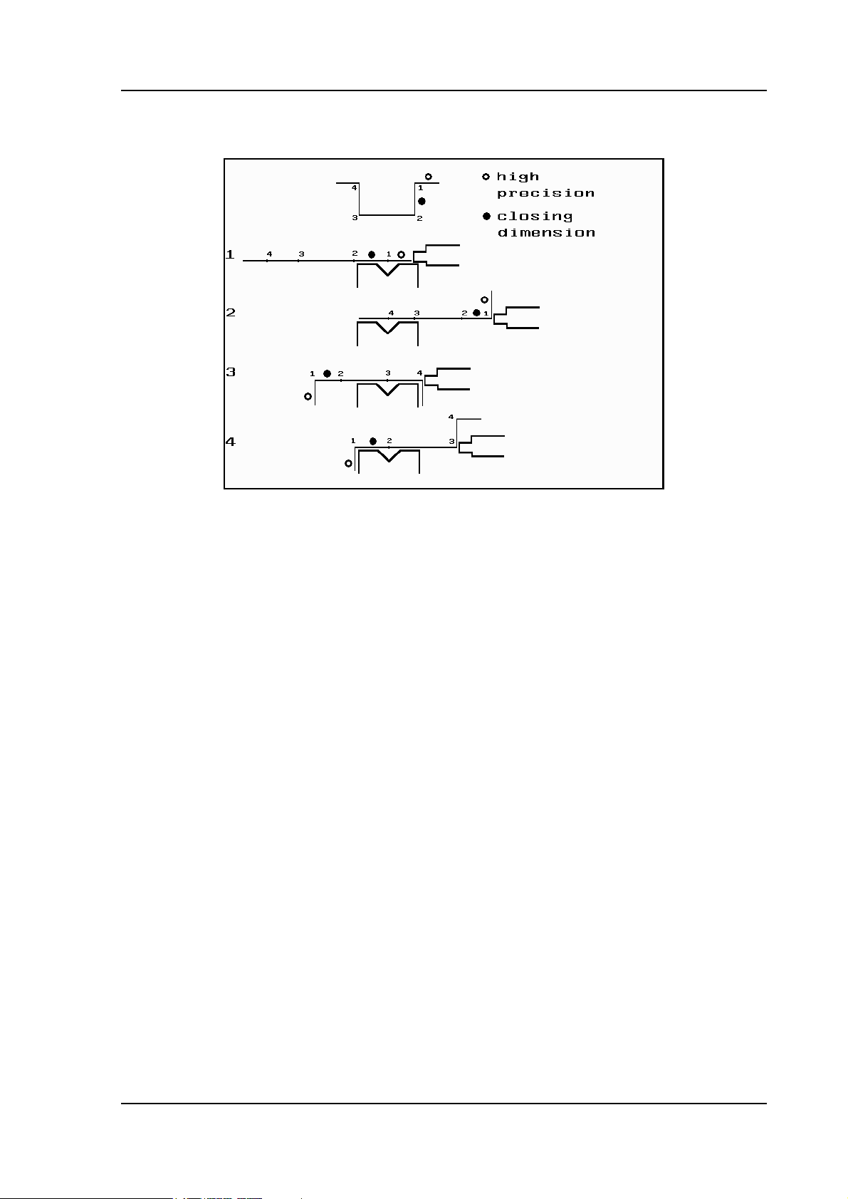
Example:
Delem
2.g
Line interval marked with the open circle should be, if possible, directly placed between back
stop and the centre of the die.
Notes:
Specifying line intervals with high precision and closing dimensions may result in longer production time.
Also it will have priority over the "front extend ratio", if that is set to "comply if possible". See
section 2.5.
V0606, 2.7
Page 28
2.4. Large Radius: Bumping
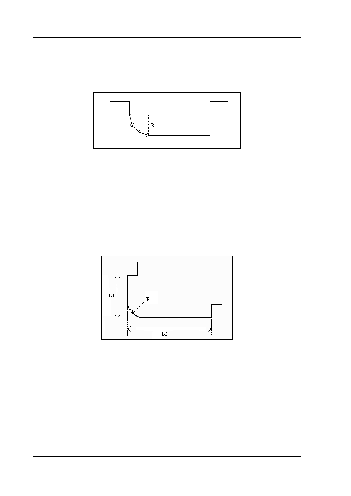
To make a bend with a large radius, the control uses the bumping method. With this method, a
large radius in a product is obtained by a series of slight bends in succession.
2.h
To program such a bend, you must program the following parameters:
radius = the desired radius
segments = number of segments
The number of bends in this radius is the number of segments plus 1.
The more segments you select, the more bendings will be used to create the programmed
radius within a smaller tolerance. With a high number of segments you will need a smaller Vdie opening to be able to bend in a proper way. Which value is acceptable as maximum for the
V-opening of the die is calculated and displayed on the screen.
For the definition of the line lengths to be programmed in the part connected to a bump radius
segment, see figure 2.i.
2.i
Lengths L1 and L2 must be equal or bigger than the radius R.
When you must program such a bend, first program a standard angle with adjacent sides. Then
put the cursor back on the angle and press the function key ‘bumping’ (S2). You will be
prompted to program the radius and the number of segments. After programming these parameters the radius is drawn in the product and the maximal V-opening which can be used is displayed on the screen. This is shown in figure 2.j.
V0606, 2.8
Page 29
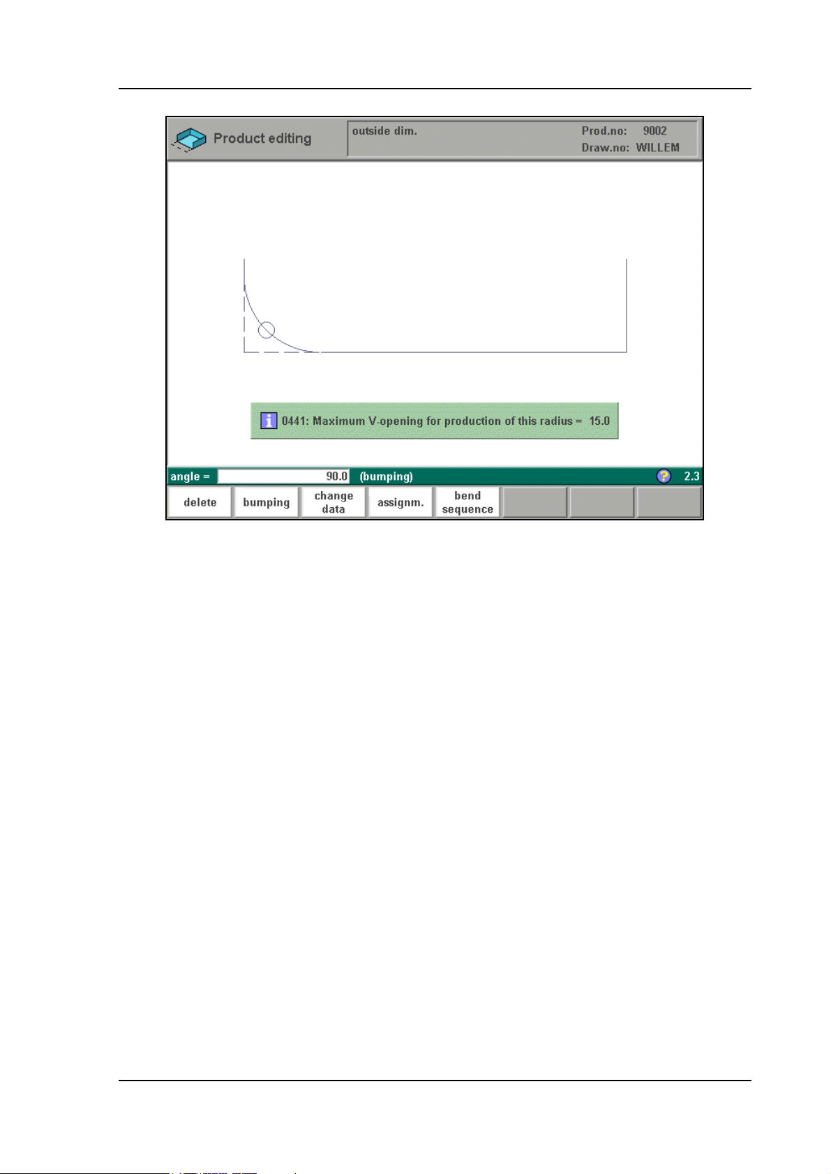
Delem
2.j
Specification items:
Radius input:
min. value = 0.1 mm
max. value = 2500.0 mm
In the ‘assignments’ menu, it is possible to modify the way the radius bend is divided into segments. See section 2.5 for more information.
2.5. Assignments
Pressing ‘Assignments’ results in the parameter pages.
If Variants programming is active (indication 'Variants On' in the title bar), a warning is given
that corrections will be lost. Press 'Yes' to proceed with the assignments or 'No' to go back to
the edit screen.
See section 2.8 for more information about variants progamming.
Automatic bend sequence computation works with several criteria in order to find an optimum
between a minimum production time, handling possibilities without product/machine and
product/tool collision.
In order to find one of the optimums you must program several computation parameters with
which the bend sequence can be computed.
Some of these parameters are machine related, axis speeds a.o. and some are related to handling possibilities and turn times.
There are three screens with parameters for 2D programming.
V0606, 2.9
Page 30
Function keys:
2.k
previous
page
next page
V0606, 2.10
load
defaults
save as
defaults
end To go back to the drawing.
To load default assignment settings. It is possible to
determine a set of assignments which have the most optimal values to work within your surrounding. This set can
be stored into the internal memory by pressing softkey S4
(save as default). While programming another product
you can recall this previous fixed set by loading the values via softkey S3.
Save as default assignments settings
Page 31

Delem
• Parameter explanation
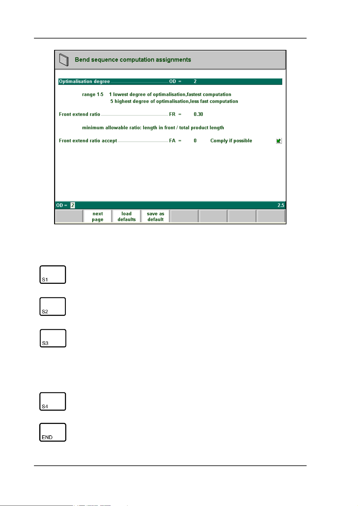
Optimalisation Degree . . . . . . . . . . . . . . . . . . . . . . . . . . . . . . . . . . . . . .OD=
Range 1-5.
The number of alternative sequences to be computed for each bending must be entered
here.
The higher this number the more alternatives are to be examined by the processor, so the
longer the computing time will be.
Front Extend Ratio. . . . . . . . . . . . . . . . . . . . . . . . . . . . . . . . . . . . . . . . .FR=
Range 0.0 - 1.0.
This is the ratio of the minimum allowable length of your product which extends in front
of the press to the total blank length of the product. You must have a minimum length of
your product in front of the press to be able to handle the product.
Front Extend Ratio Accept . . . . . . . . . . . . . . . . . . . . . . . . . . . . . . . . . .FA=
- In case programmed 0 (comply if possible):
This means that when possible the computer tries to comply to the front extend ratio and
only when this will result in no solutions to be found it will accept that the length in front
is smaller than the specified ratio.
- In case programmed 1 (comply always):
The computer will always comply to the front extend ratio. This may result in no solutions to be found.
Press the key to select the required setting.
V0606, 2.11
Page 32
• Parameter explanation
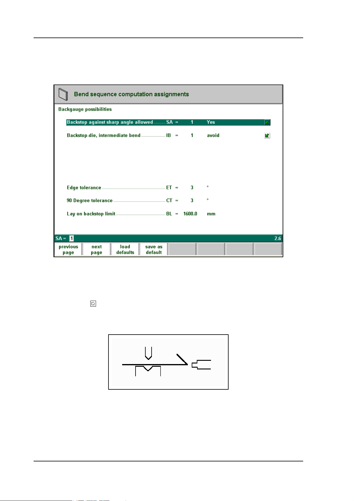
Backgauge possibilities
2.l
Backstop against sharp angle allowed . . . . . . . . . . . . . . . . . . . . . . . . .SA=
0 if not allowed
1 if allowed
Press the key to select the required setting.
Specify if backstop may be placed against an angle smaller than 90°.
2.m
V0606, 2.12
Page 33
Delem
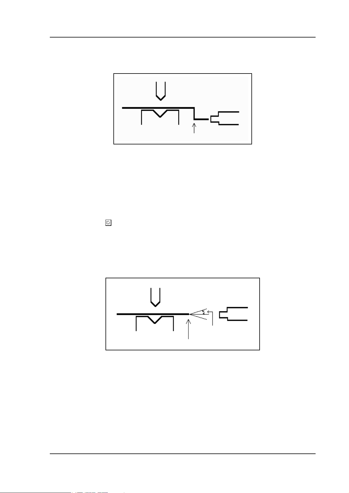
Backstop die, intermediate bend . . . . . . . . . . . . . . . . . . . . . . . . . . . . . .IB=
Set to allow if there may be a bend between the die and backstop.
2.n
Selection possibilities:
0 = permitted
1 = avoid: tries to avoid with low priority
2 = if not avoidable permitted: if it results that no solutions are to be found, than it is permitted
3 = prohibited: never allowable
Press the key to select the required setting.
Edge tolerance. . . . . . . . . . . . . . . . . . . . . . . . . . . . . . . . . . . . . . . . . . . . .ET=
In case backstop is against flat plate an angle tolerance is allowed (deviation from horizontal).
To be programmed in degrees of tolerance (0 - 90° input)
2.o
V0606, 2.13
Page 34
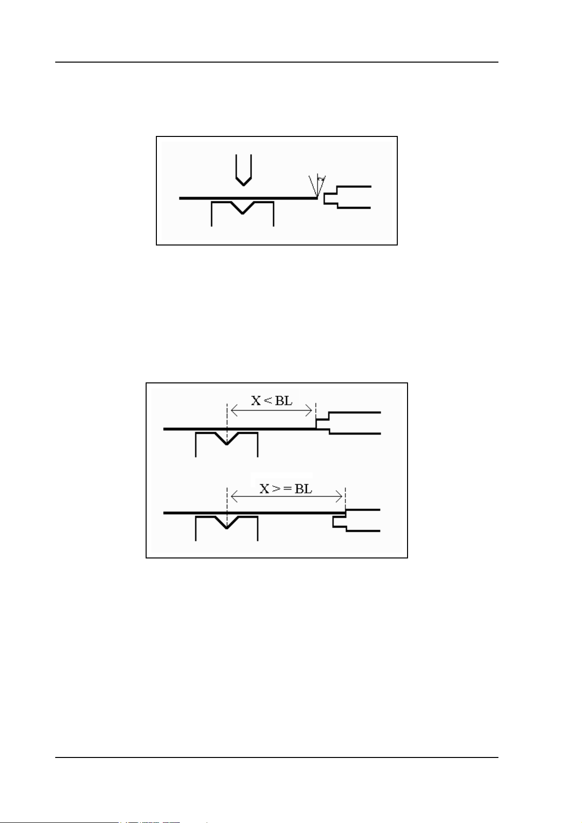
90 Degree tolerance . . . . . . . . . . . . . . . . . . . . . . . . . . . . . . . . . . . . . . . .CT =
The maximum allowed deviation from vertical (90°), when the backgauge is against a
bent angle which is not 90°.
2.p
Lay-on backstop limit . . . . . . . . . . . . . . . . . . . . . . . . . . . . . . . . . . . . . .BL=
This parameter (mm) is usefull in case the pressbrake has been equiped with backgaugefingers on a moving R-axis, having a so-called “lay-on” construction.
When the length of the plate at the backside of the machine is greater than this limit, the
X-axis and R-axis positions will be corrected automatically so the plate will rest on the
backgauge finger (0 - 3200.0 mm).
This is only possible if an automatic R-axis is enabled.
V0606, 2.14
2.q
Page 35
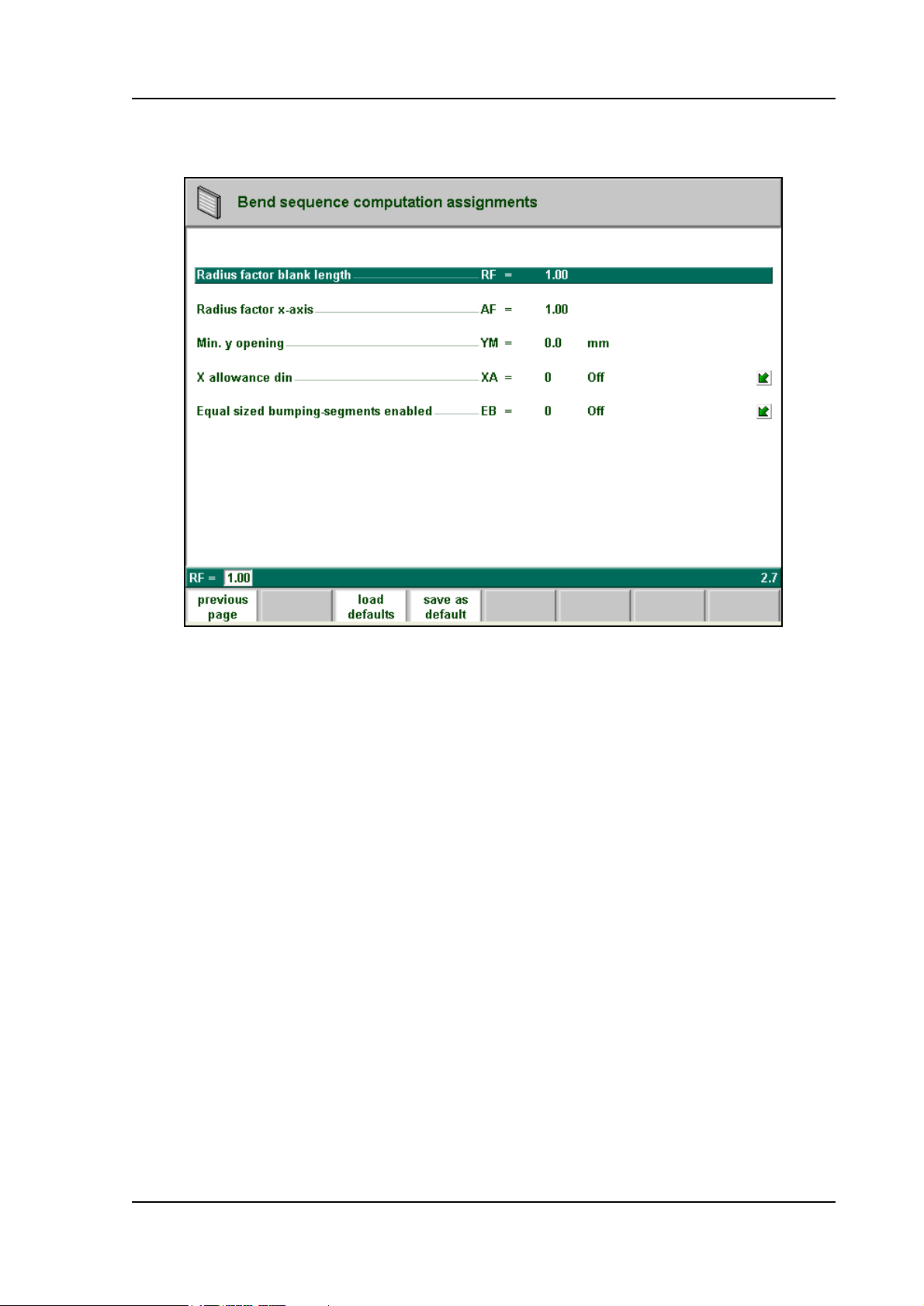
• Parameter explanation
Delem
2.r
Blank length computation
After postprocessing, the controller calculates the developed length of your product and the
bend allowance.
Important for the developed length calculation and the bend allowance is the inner radius of
the bends.
For each of these computations a correction factor can be programmed (RF and AF).
Radius factor blank length . . . . . . . . . . . . . . . . . . . . . . . . . . . . . . . . . .RF=
The computed inner radius is multiplied by this factor to correct the total developed
length of the product. The initial value of RF is 1.
Radius factor X-axis position . . . . . . . . . . . . . . . . . . . . . . . . . . . . . . . .AF=
The computed inner radius is multiplied by this factor to correct the X-axis position in
order to have a correct product dimension after each specific bend (bend allowance).
This factor can be checked by making a product with just one bend and a certain product
dimension e.g. 100 mm (outer dimension). See figure 2.s.
The controller computes the X-axis position necessary to obtain L=100 as shown in figure 2.s.
The accuracy of the length L is dependent on the material parameters like thickness, strength
and kind of material. In order to have a correction possibility with the radius factor AF you can
optimise this computation.
RF and AF do not influence each other. It is recommended that first you optimise the AF factor
V0606, 2.15
Page 36
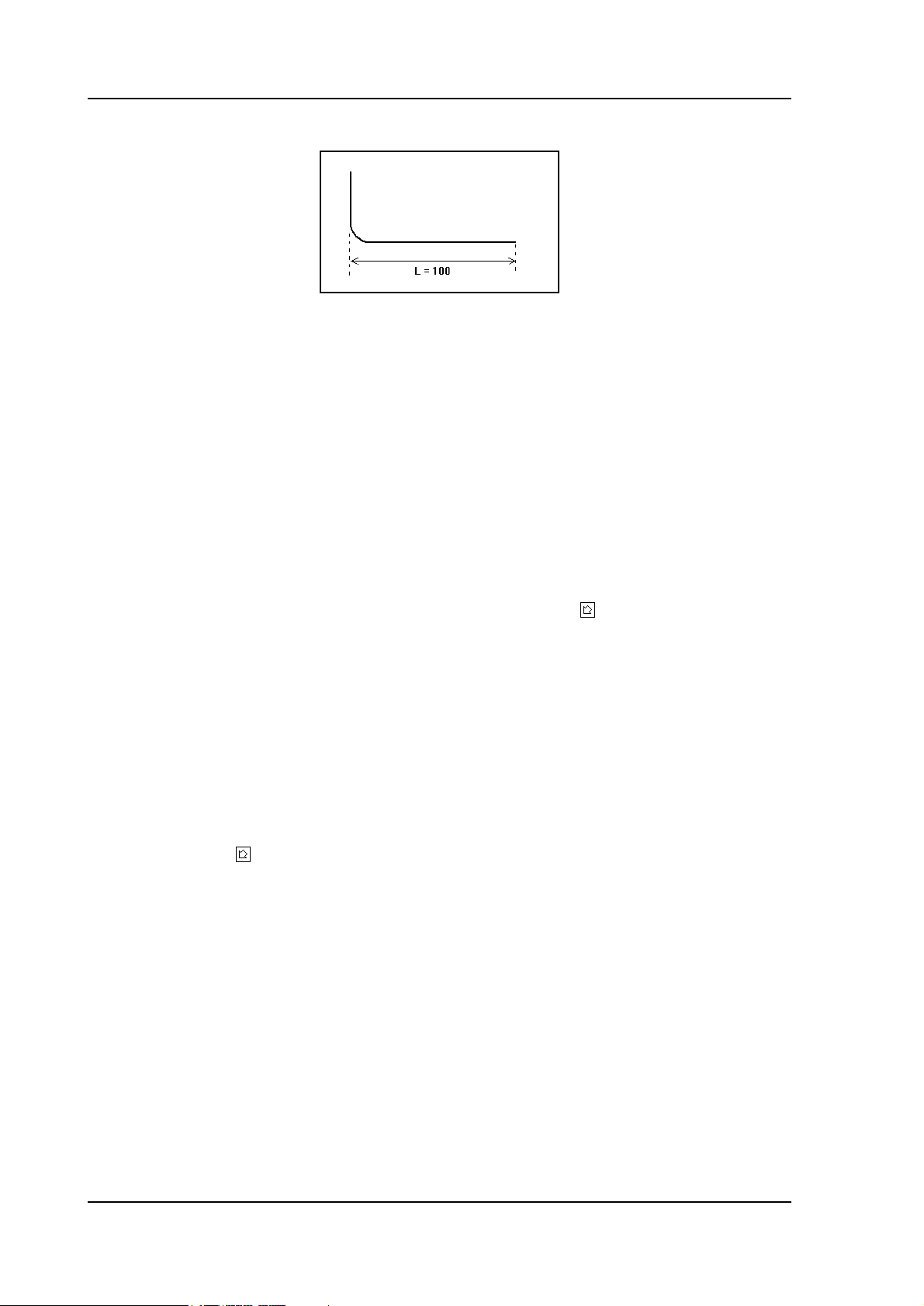
for your product and thereafter find the correct value for the developed length correction RF.
2.s
Minimum Y-axis opening . . . . . . . . . . . . . . . . . . . . . . . . . . . . . . . . . . .YM=
During postprocessing of the programmed product, the control always computes an optimal opening of the pressbeam to handle your product. Here you can program a minimum
required opening. The programmed value is the distance above the speed change point
MUTE.
X-allowance DIN . . . . . . . . . . . . . . . . . . . . . . . . . . . . . . . . . . . . . . . . . .XA =
For the calculation of the developed length and bend-allowance during the postprocessing of a graphical 2D product, a Delem formula is used. It is also possible to select the
standard DIN-formula (DIN6935).
0 = Delem formula (OFF).
1 = DIN formula (ON).
Default setting is zero for the Delem formula. Press the key to select the required setting.
Equal sized bumping segments enabled. . . . . . . . . . . . . . . . . . . . . . . .EB=
When a product has a radius bend, the segment size is computed from the number of segments, which has been defined by the user. Standard the first and last segment are calculated half the size of the mid segments to obtain a better result. However, it can be a
problem selecting a die suitable to bend these small segments. Therefore the control can
calculate an equal size for all segments. This can be defined with this parameter.
0 = disabled (no equal sizes).
1 = enabled (equal sizes).
Press the key to select the required setting.
When this parameter is set to 1, all segments will have an equal size.
If it is set to 0 the calculation is as before, including half size segments. If in this case a
problem with the size of the V die is detected in the bend sequence menu, the user is
asked whether or not to select a re-calculation with equal size segments.
2.6. Bend sequence
After completion of your drawing, with function key S5 you select the "bend sequence" mode.
You will have to enter the number of the machine lowerside, the die, the machine upperside
and the punch first. This number corresponds with the number in the respective tool libraries
(menu number 7, 8, 9 and 10).
If the number entered is not known, the controller prompts the message "not programmed".
You have to program the machine parts and tools before you can compute the bend sequence.
Programming can be done via the respective selections in the program menu. The several tools
V0606, 2.16
Page 37
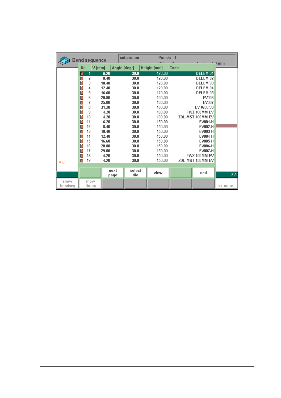
Delem
as available in the respective tool libraries can be shown on the screen with S2 (show library).
This selection will give an overview of the tools including the main properties of each tool.
2.t
If this overview is not sufficient to select a tool, press the function key ‘view’ and the key
‘graph. dir’ to get a graphical overview of available tools.
V0606, 2.17
Page 38
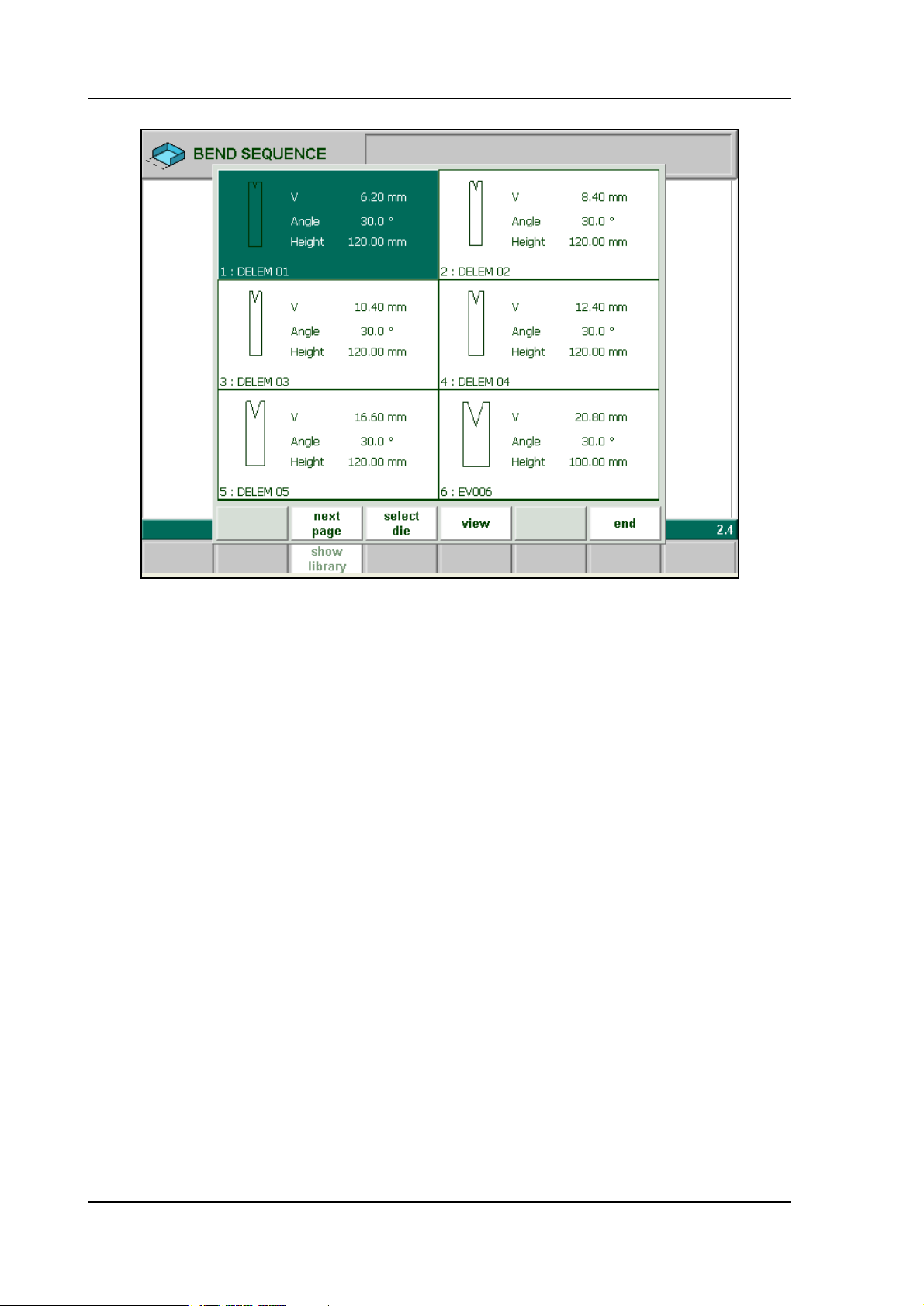
2.u
In your machine and tool library you can program 10 different machine uppersides, 10 different machine undersides (tables), 99 different dies and 99 different punches. One of each must
be selected, and can also be changed during the bending sequence determination. These selections are prompted in the lower left corner of the screen. Within the bend sequence screen, the
softkey ‘show library’ will remain available to get a graphical overview of the tool library as
shown above.
After specifying machine part and tools the product and machine will be drawn on the screen.
V0606, 2.18
Page 39
Delem
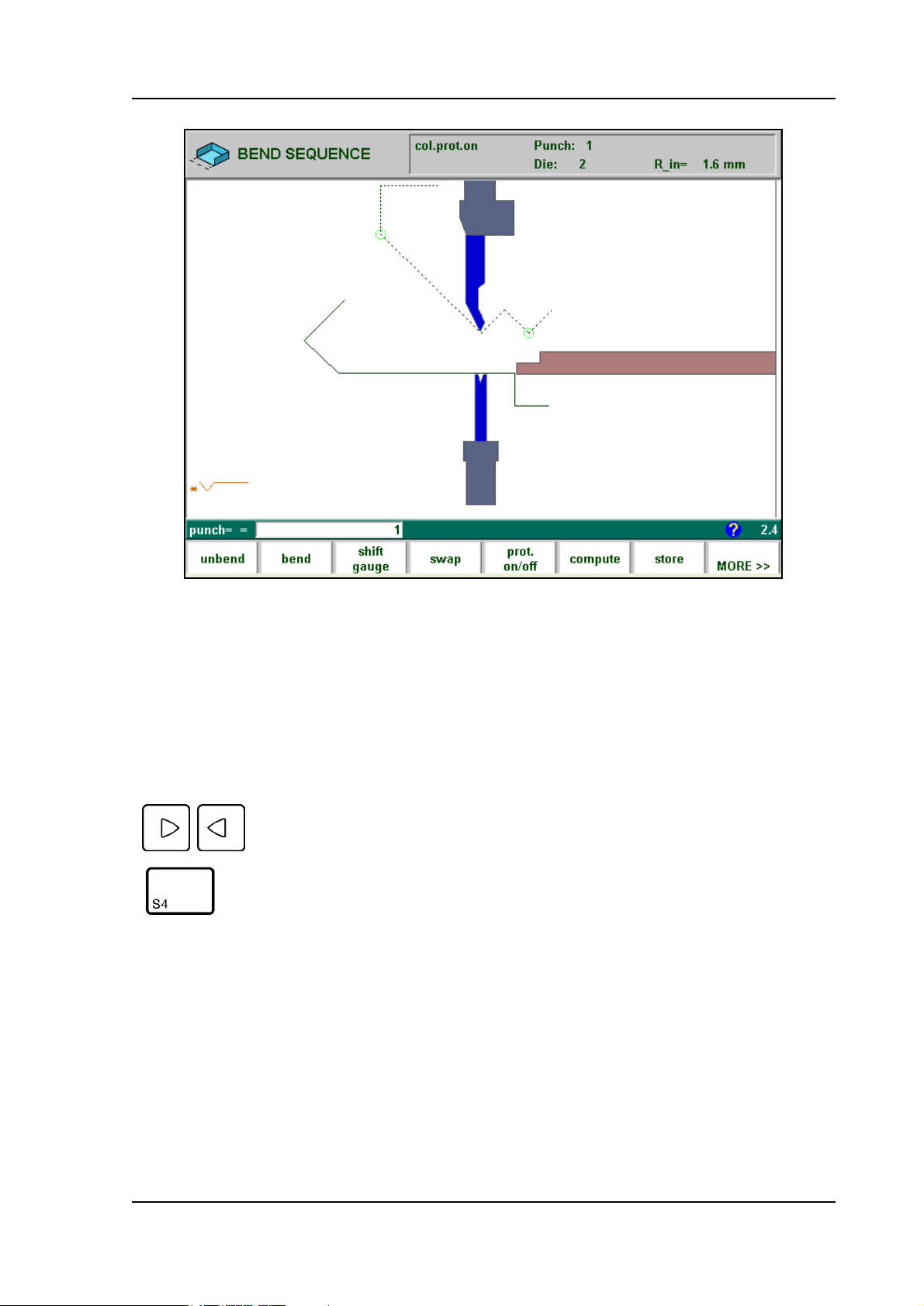
2.v
The product, as it was drawn, is placed directly under the punch, at one of the last bending
positions possible.
The shape of your product before this last bend is placed on top of the die. A bigger circle on
an angle indicates that this bending is also possible without collision.
A complete overview of available softkeys in this screen is given on page 2.25. The function
key ‘more>>’ serves to switch between the primary and secondary row with function keys.
With these keys you can select any of the other bendings which you
If the product has collision with the tools or machine it will be indicated via a warning message
on the screen.
prefer to be the last bending. The bends possible are indicated with
the round cursor.
V0606, 2.19
Page 40
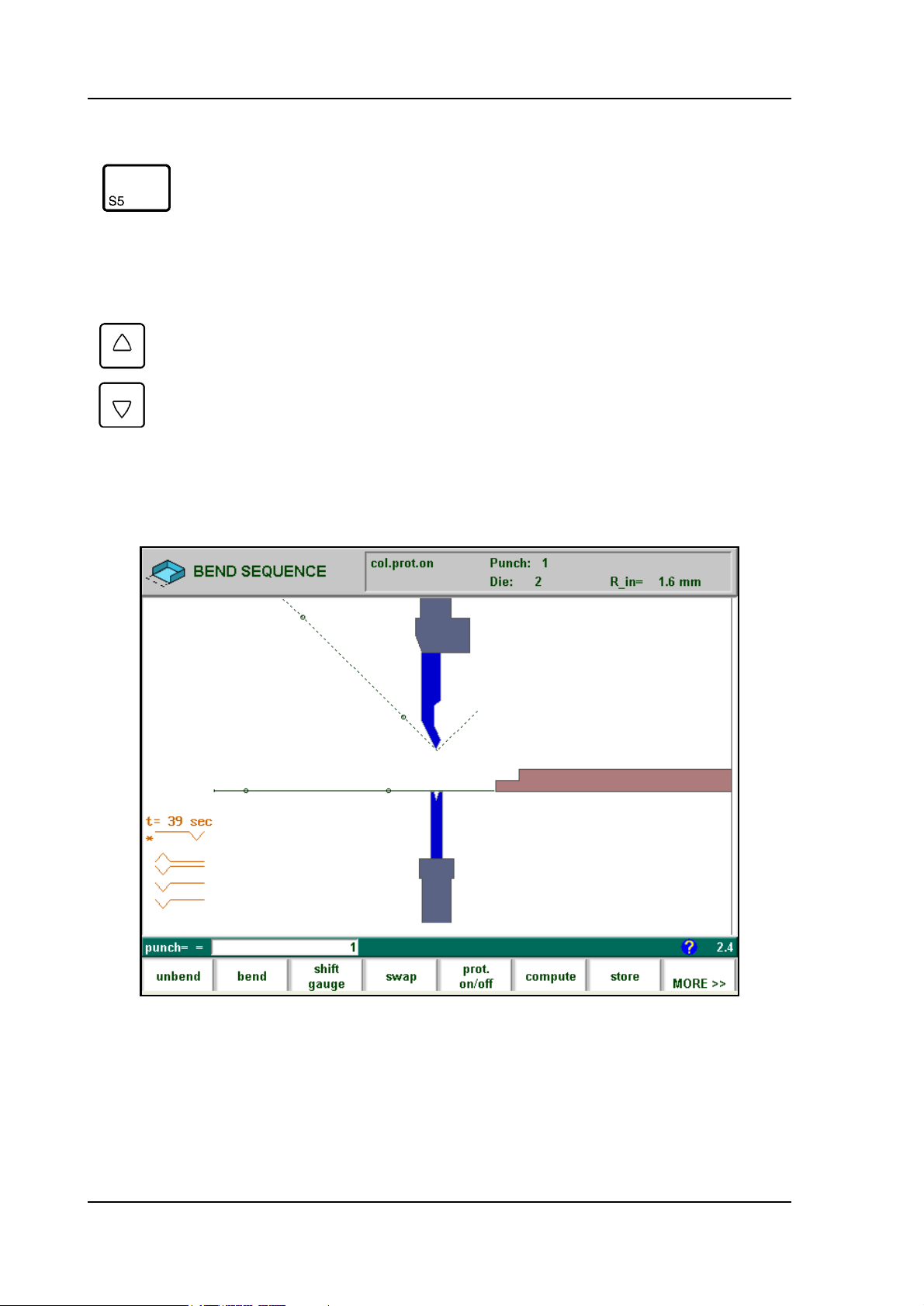
With this function key you can switch the collision protection check
on or off.
This is indicated at the top of the screen. When you have selected
collision "off" you can also select other bends which will give collision with the tools or machine parts.
The inner radius resulting after this bend is displayed at the top of
the screen.
To enlarge or reduce the complete drawing.
After pressing "unbend" the position of the bending is indicated by a small circle, see figure
2.w.
2.w
Note:
A big radius (bumping) is shown during bend sequence computation but is treated as a single
bending.
The CNC-data of the bendings necessary to produce the radius are computed during postprocessing.
V0606, 2.20
Page 41
Delem
The bendsequence computation can be activated from the last bending upwards to the first, but
it is also possible to activate for instance the last 2 bendings manually and to compute the optimal bendsequence for the rest of the bendings. This computation will start from the bending
indicated with an asterisk. With this possibility and with help of the swap function you can
compute several possibilities.
During the automatic bendsequence computation you can always
interrupt the computation by pressing "Abort computation".
If the computation is interrupted, the computer will give most of the
times a suggestion for the bendsequence. It is possibly not the most
optimal solution.
When a bendsequence has been determined, a CNC program can be
calculated and stored. This process is called postprocessing. When
postprocessing is finished, the ‘blank length’ of the product is displayed.
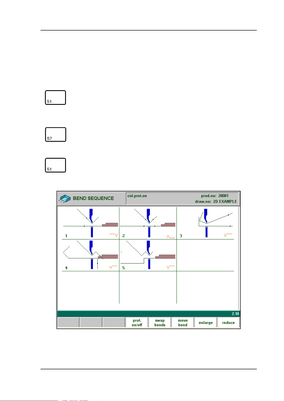
(second row) Open a graphical overview of the bend sequence, in
order to have a visual check.
2.x
The images in this graphical overview can be zoomed-in or zoomed-out with the cursor- up
and cursor- down key. The function keys S7 and S8 enlarge or reduce the number of images
that is displayed on the screen at once (minimal 4 and maximal 25).
V0606, 2.21
Page 42

Function keys:
Swap bends Let two bends exchange place in the bend sequence.
Move bend Move a certain bend to another place in the bend
sequence.
Enlarge Enlarge all bend pictures, thereby decreasing the number
of bends shown on the screen.
Reduce Shrink the bend pictures, thereby increasing the number
of bends shown on the screen.
Move bend
In the graphical overview of the bendsequence, it is possible to change the order of bends simply by moving a bend to another place. Press the button ‘Move bend’ and the number of the
first bend is highlighted. Use the arrow keys to move this cursor to the bend that must be
moved. When the correct bend number is highlighted, press the enter key to select this bend.
Now use the arrow key to move the bend to the right place in the sequence. If the bend is on the
correct place, press 'enter' to confirm.
Swap Bends
With this command, two bends can change place in the bend sequence. Press the ‘swap bends’
button. Move the cursor to one of the required bends and press the ‘swap’ button or press enter.
Then move the cursor to the bend with which it must be swapped and press the enter key or the
‘swap’ button. Now the bends have been swapped. If for any reason the action must be cancelled, press the softkey ‘abort swap’ during the procedure.
• Restoring a bend sequence
A (partly) determined bend sequence is not automatically reset after leaving the bend sequence
menu.
After you re-enter the bend sequence menu it is possible to continue with the existing bend
sequence.
If you re-enter the bend sequence menu you have the following options:
V0606, 2.22
Page 43
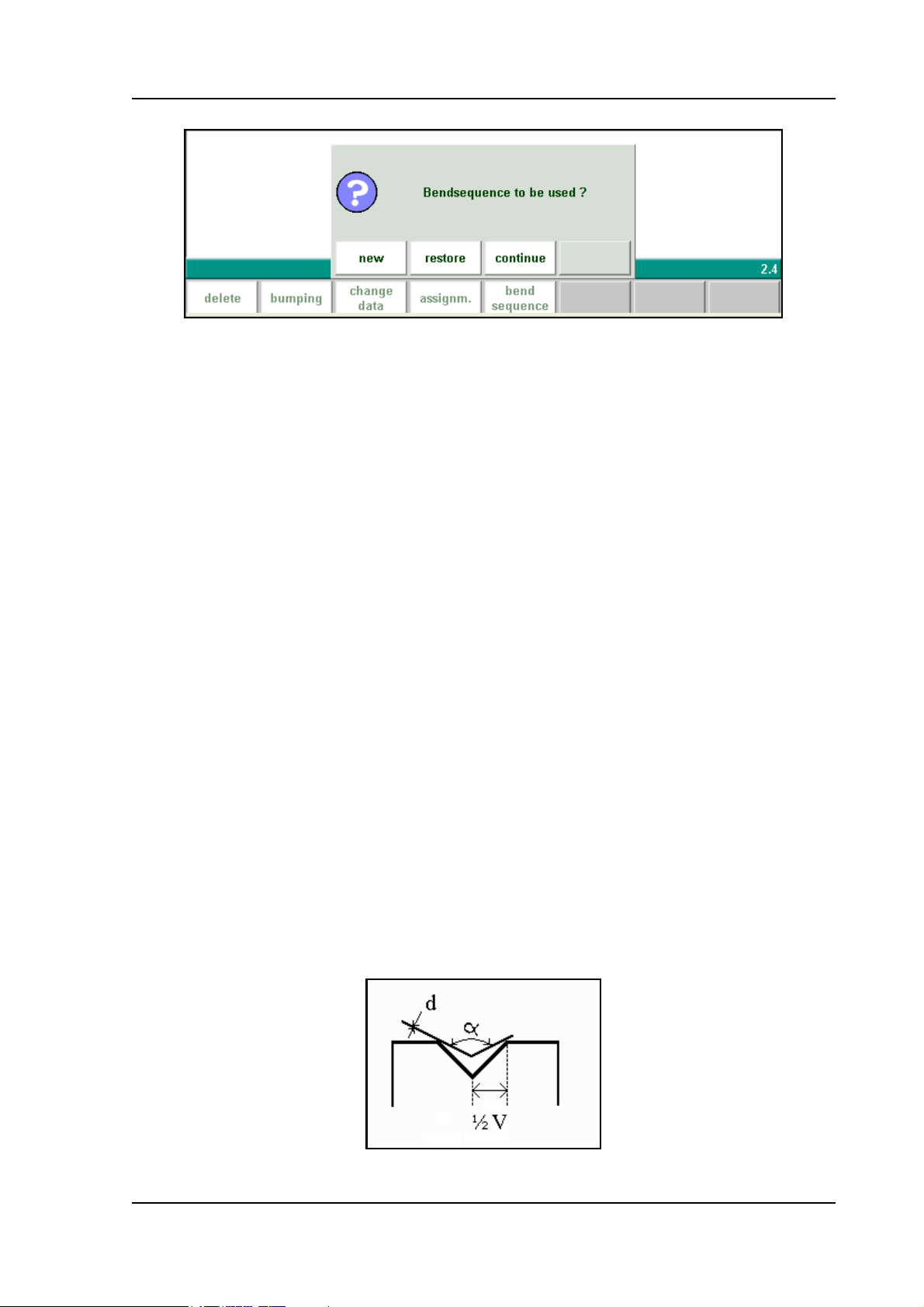
Delem
2.y
‘new’ start new bend sequence, the existing bend sequence is
reset
‘continue’ continue with current bend sequence, the existing (par-
tial) bend sequence is restored and shown on the screen
If you have loaded a drawing from which a postprocessed bending program already exists,
there is a third option when you enter the bend sequence menu:
‘restore’ restore bend sequence from postprocessed program, the
bend sequence is restored from this postprocessed bending program and shown on the screen
If you have drawn a new product in the menu "Product drawing" and you enter the bend
sequence menu for the first time, there is no existing bend sequence and postprocessed program yet, these previously mentioned selections are not shown.
• Minimum bending length
The minimum possible bending length will be calculated from the V-opening parameter (½ V),
but also depends on the angle to bend and the thickness of the material to be bend, see figure
2.z. If the programmed value for the wanted product does not correspond with the minimum
possible length, you will get a warning message on the screen.
2.z
V0606, 2.23
Page 44
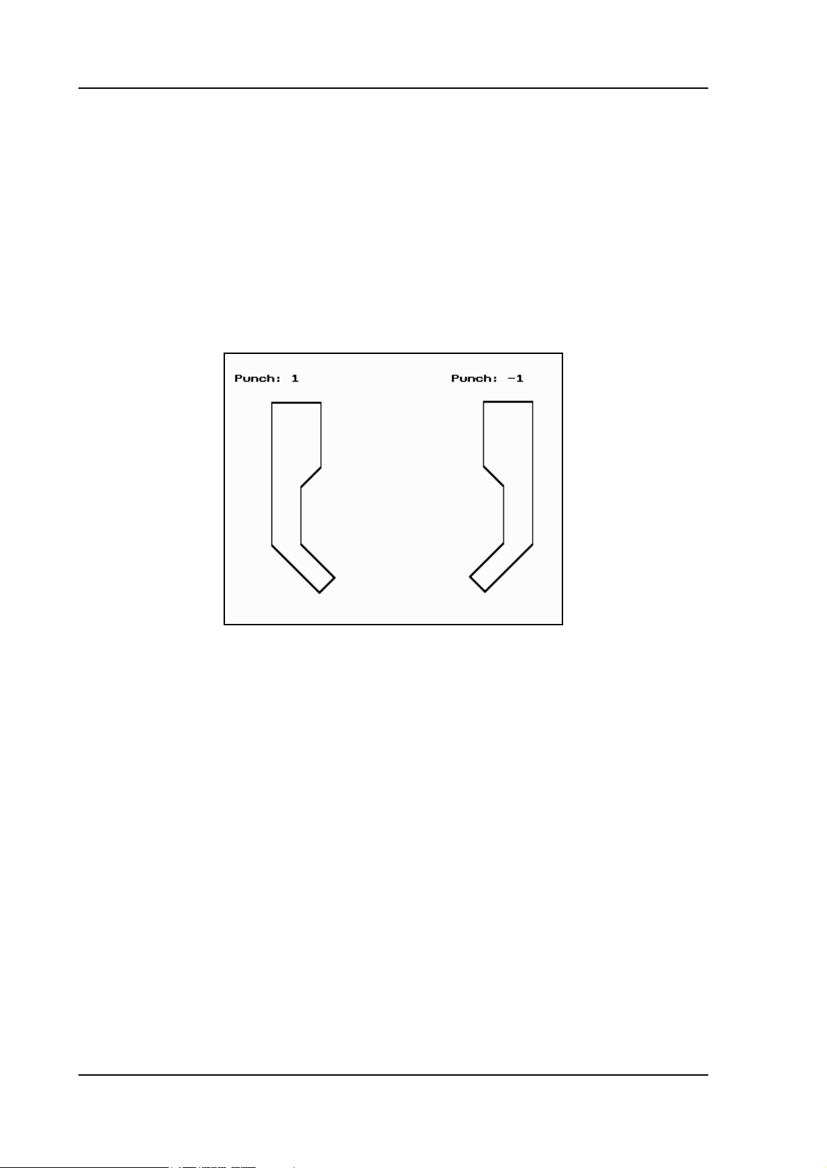
• Machine/Tool selection
At each bend you can select one of the tools or machine shapes which are present in your
library. The displayed number is the number of the tool and machine part which is presently
selected.
Entering a new number will select another tool or machine part which will be drawn directly
on the screen.
With the "enter" key you can toggle between punch-, die-, machine upper- and lower part number.
It is also possible to turn the punch and die with respect to the machine shapes. To achieve this,
the tool number must be programmed negative.
2.aa
In order to get a graphical overview of the available tools while you are in the bend sequence
menu, press the function key 'show library' (S2). If pressed, an overview appears of available
tools.
Which type of tools is shown depends on which type was prompted in the bend sequence
screen: punch, die, machine upper- or lowerside.
• Turn indication
In the lower left corner a bend turn indication is displayed at each bend of bend sequence.
V0606, 2.24
Page 45
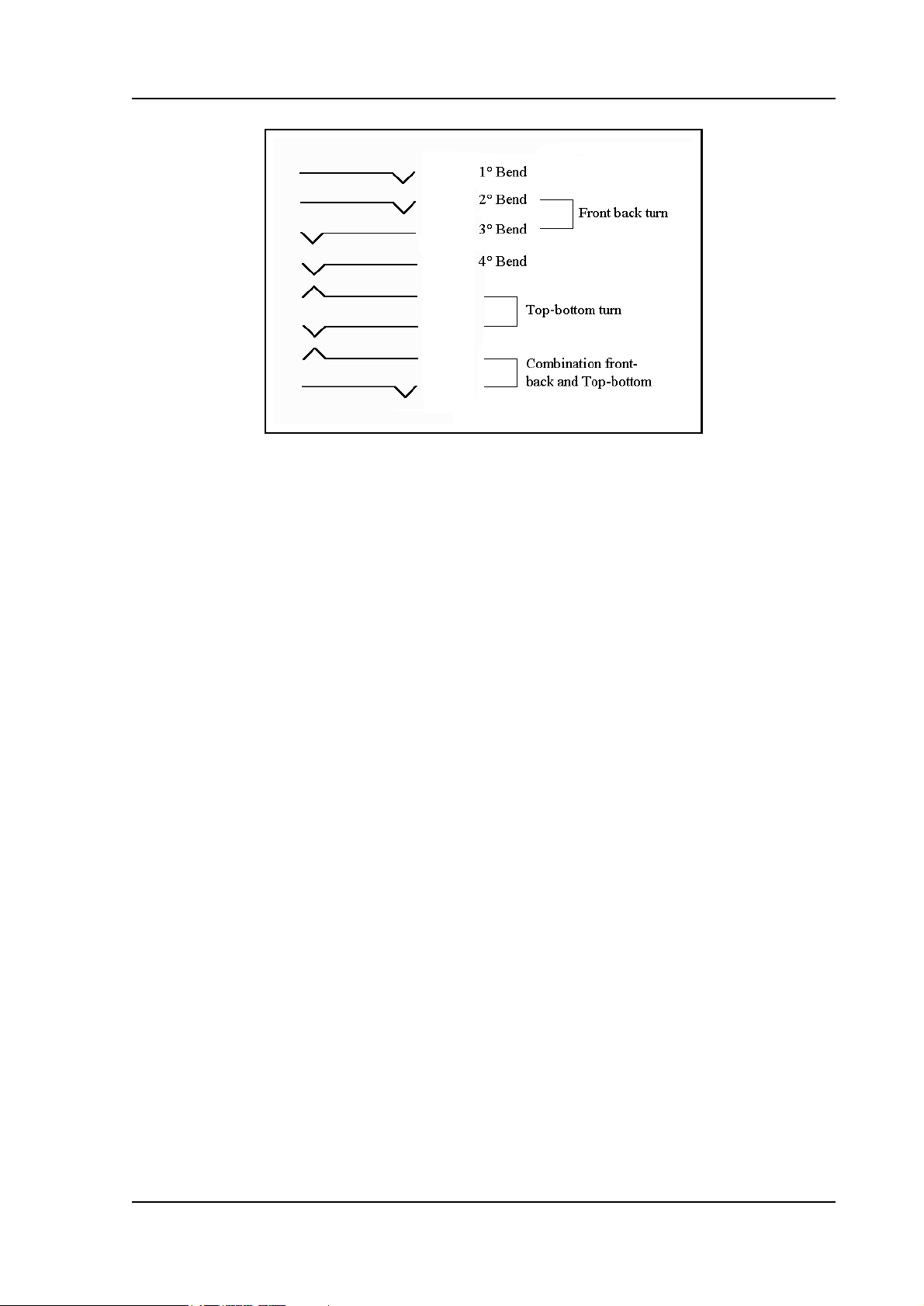
2.ab
The asterisk indicates which bend is presently displayed.
Delem
• Production time
At the top of the turn information (before the first bend) the total production time is indicated.
This time is calculated from the following settings:
- X-axis speed
- Y-opening and Y-axis speeds
- R-axis speed
- Turn time programmed in the turn time table of the assignment
With automatic bend sequence computation the controller tries to find the minimum production time.
• Screen data
On top of the screen some general important data is displayed.
Col.prot.on Collision and backgauge checks on or off
Punch: 1 Punch number selected
die: 1 Die number selected
R-in = 1.3 Inner radius of the bend to be obtained with selected die
Variants On Variants programming enabled: the product has a valid CNC pro-
gram that can be modified from the graphical menu.
V0606, 2.25
Page 46

• Function- and control keys summary
Function keys:
unbend/
next
bend/previous
shift gauge Select backgauge position
swap Front to back turn of the product.
protection
on/off
compute The sequence calculation starts from the bend number
To unbend the graphical product
To bend the graphical product
To switch the collision detection with collision warning
On or Off.
presently selected. This feature gives you the unique possibility to fix the bending sequence interactively, e.g.
partly manual partly automatic.
store Automatic computation of all axes positions (complete
more>> The softkeys for this mode are divided in two rows. Press
end To go back to the drawing.
Function keys secondary row:
show bendseq.
CNC program) and storage in the product library of the
postprocessed product.
this key to switch from one row to another.
To show a mosaic screen with a step-by-step graphical
overview of the bendsequence.
V0606, 2.26
Page 47
Function keys secondary row:
Delem
show
library
Control keys:
Zoom enlargement
Zoom reducement
Softkey to get a graphical overview of the tool library.
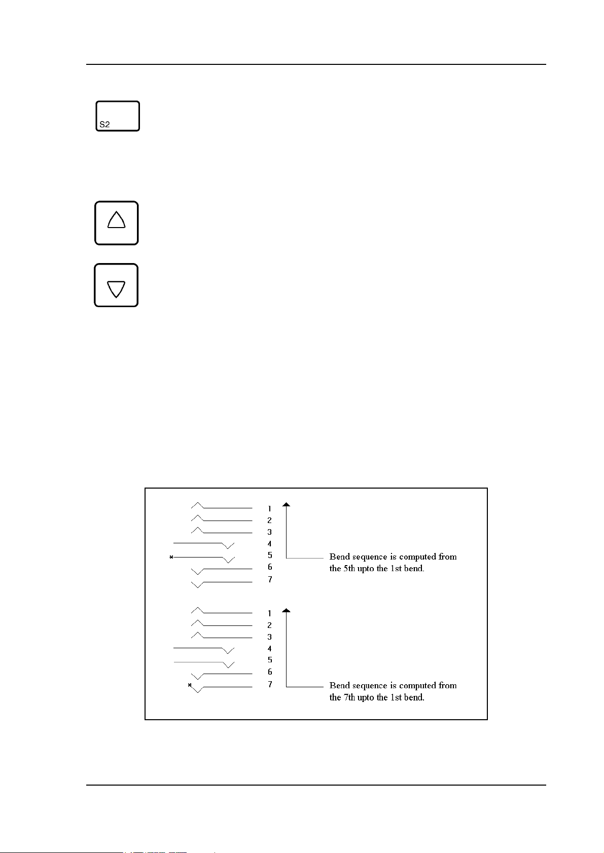
• Bend sequence computation
With ‘compute’ the bend sequence can be computed automatically.
The computation is done only with one set of tools. These are the tools selected at the last
bend.
The computation of the bend sequence starts always at the bend which is indicated with the *
at the lower left corner of the screen.
Example: Product with 7 bends
2.ac
In the first example the bend no. 7 and no. 6 are chosen manually, from 5 up to 1 thereafter are
V0606, 2.27
Page 48
computed automatically.
In the second example the complete bend sequence is computed (7 up to 1).
During the computation all assignments are important so you must be sure before starting the
bend order computation that all assignments are set correctly.
•Store
After you have completed the bend sequence a CNC-program can be generated. This generated
program will be stored in the controller program memory.
2.7. Variants programming
The term ‘Variants programming’ means that the operator can make modifications to an existing program in the graphic menu, without having to build a new CNC program from scratch.
An existing program can be altered without loss of existing corrections and bendsequence. If
such an existing program contains proper axis values and product positions then this information can stay intact, only the latest changes (angle, sheet length) are recalculated and entered
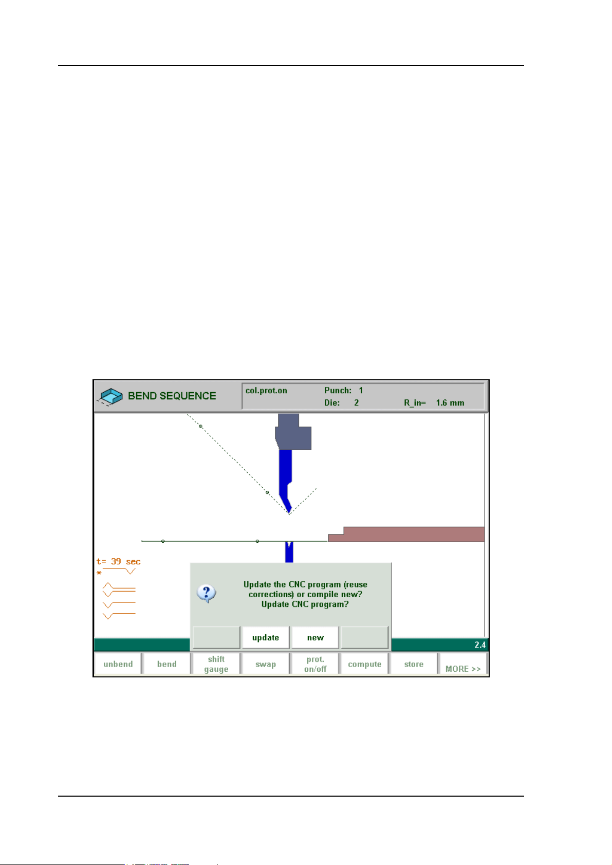
into the program.
For instance, when a side length has been altered in the graphical bend overview and the
‘store’ command is given, then a question appears how to compute a CNC program.
2.ad
When update (S4) is chosen, the existing CNC program is changed with regard to modified
values (angle, length), but other values of bend parameters stay the same. The expression ‘reuse corrections’ refers to the corrections that may have been entered in one of the production
modes. These production modes are explained in chapter 10.
When new (S5) is chosen, a new CNC program is calculated. Corrections in the existing CNC
V0606, 2.28
Page 49
Delem
program are lost.
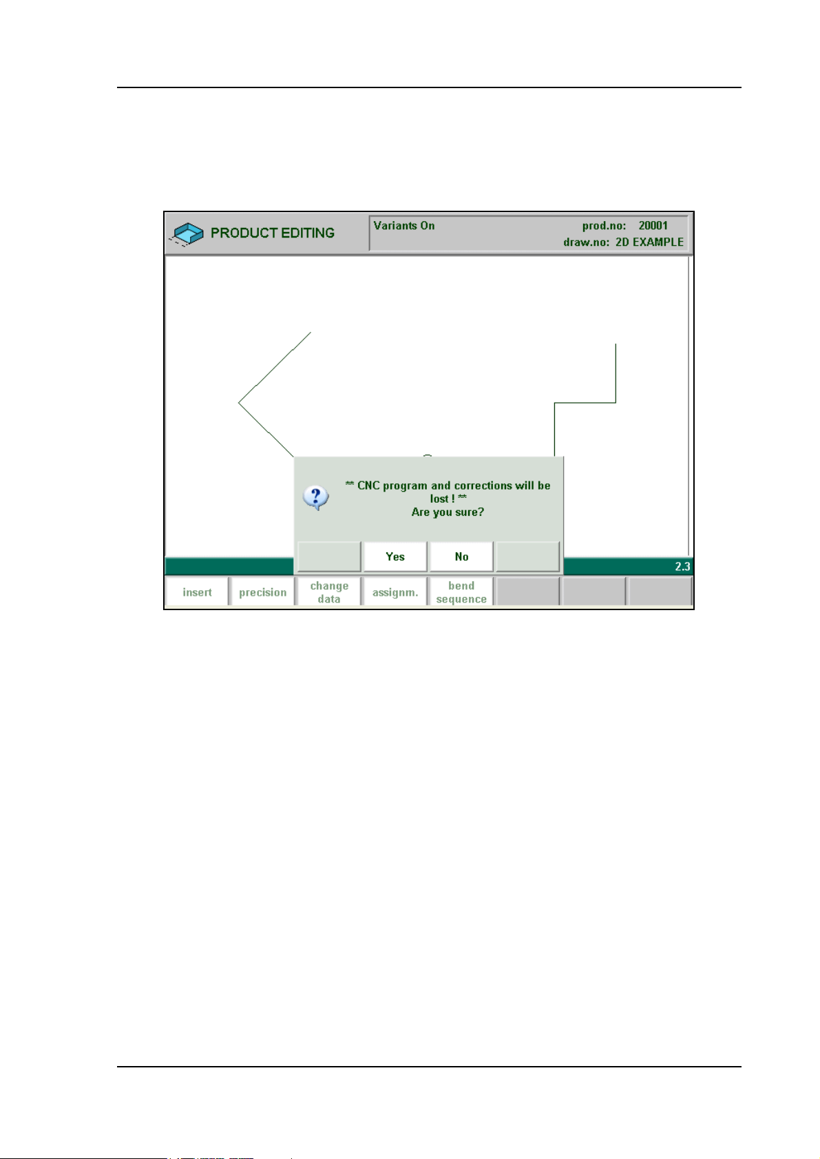
In order to keep the existing program, check that the indication ‘Variants On’ remains in the
title bar. When you start an action or command that would seriously change the program, a
warning is issued by the control:
2.ae
If you choose 'yes' (S4), the indication 'Variants On' will disappear from the title bar. This
means that the next time when a new 'postprocess' command is started, a new CNC program is
built and old corrections will be lost. When 'No' (S5) is chosen, the action is cancelled and
'Variants on' remains.
The message "CNC program and corrections will be lost" is not literally true. The CNC program is still present, but it cannot be updated anymore from the graphical menu. If the old
CNC program must be stored, it is still possible to go to ‘data edit’ mode and store the program
under a different product number.
V0606, 2.29
Page 50

V0606, 2.30
Page 51
Delem
4. Data preparation/Data edit
4.1. Introduction
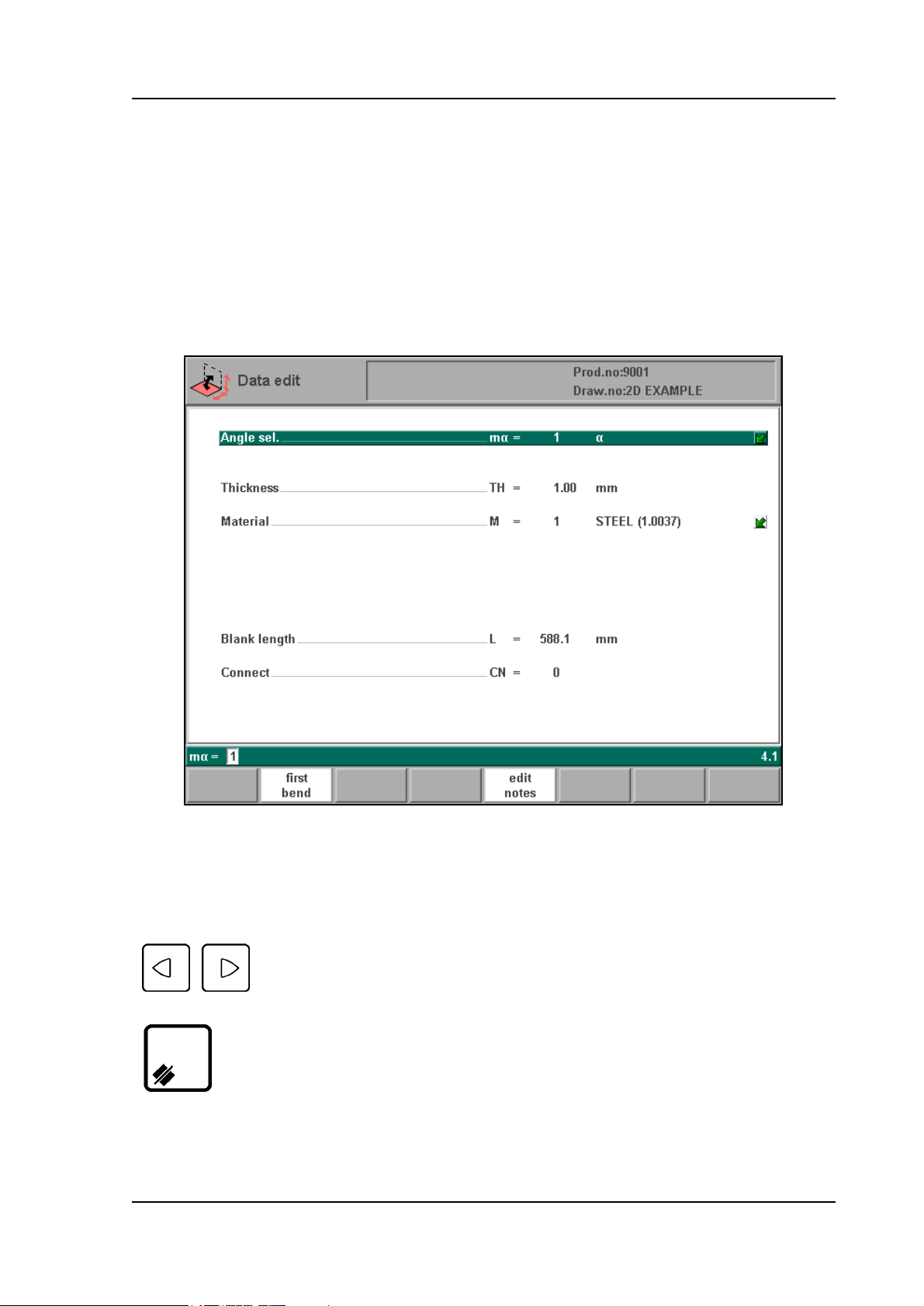
To create a new CNC program, choose ‘Data preparation’ in the main menu.
To edit an existing CNC program, choose ‘Data edit’ in the main menu.
In both cases, a screen as shown below should appear. Programming and changing data is done
in the same way for both modes.
To edit a program that is not currently loaded, choose ‘Product selection’ in the main menu. In
the offered list, you have to select the wanted program number.
4.a
This page gives all data which are the same for every bending of the program (main data of
program).
For placing the cursor at one of the parameters. The
value entered for the selected parameter appears in the
entering field, situated in the lower left corner.
The input can be cleared for entering new input data.
Data has to be given to be able to continue programming.
V0606, 4.1
Page 52
Function keys:
first bend The cursor jumps to the page with the first bend informa-
edit notes Open a window with notes about the current product.
END Finishing the data preparation and returning to the pro-
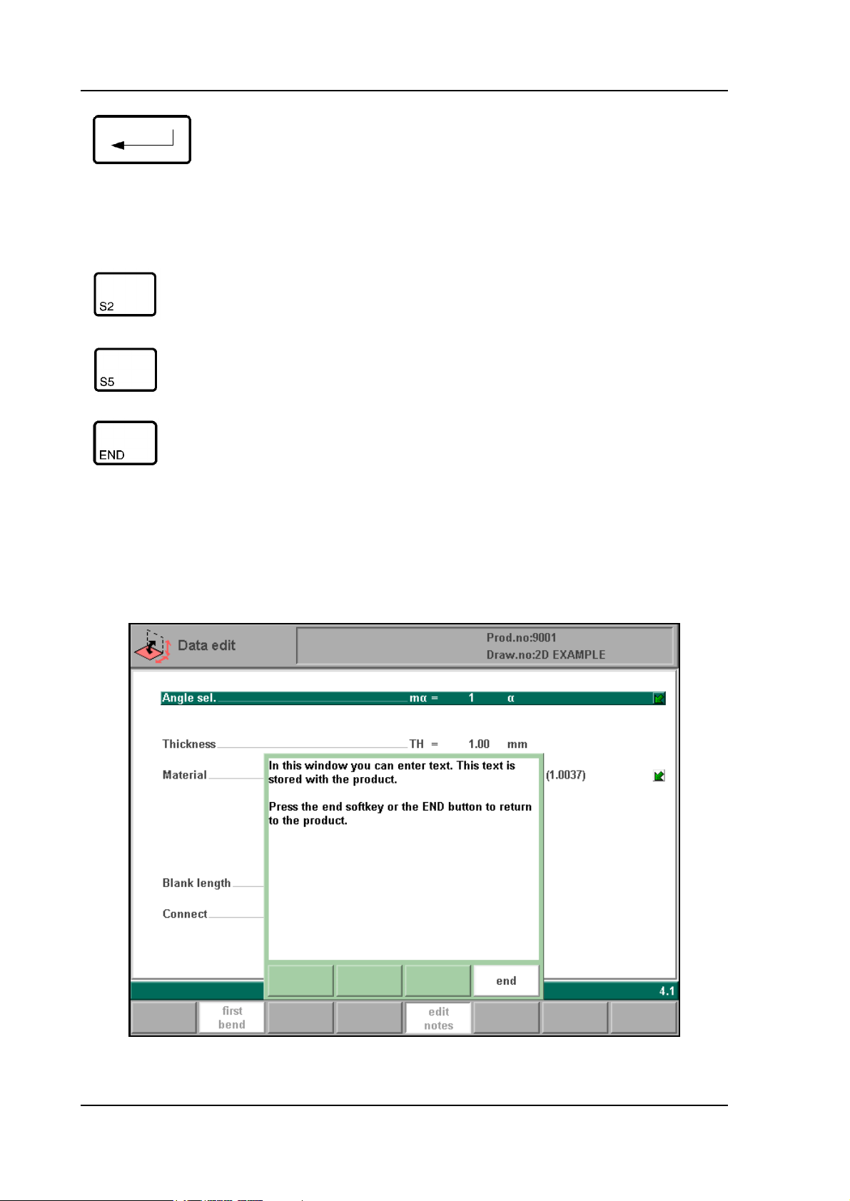
• Edit notes
After pressing the enter key the programmed value will
be placed at the corresponding parameter.
tion.
gram menu.
It is possible to add a note to your product, in order to store comment or background information about the current product.
V0606, 4.2
4.b
Page 53

Delem
The note is a simple text field, it has no influence on product values or bend sequence calculations. The maximum allowed length of the note is 1023 characters.
The possible characters in a note are the following:
a-z
A-Z
0-9
?!%*/\+-:;,._
To edit a note, a keyboard is needed. Depending on the control type, you can connect an external USB keyboard or use an integrated keyboard option.
To exit the note, press the END key choose function key ‘end’. If you have made changes in
the note, you are asked whether or not to save the changed note or to leave it as it was before.
• Parameter explanation
Angle selection . . . . . . . . . . . . . . . . . . . . . . . . . . . . . . . . . . . . . . . . . . . .mα
Selection of the programming mode for the Y-axis.
0 = absolute: program the absolute Y-axis position for a bend.
1 = α: program the angle to bend. The required Y-axis position is computed.
Depending on this parameter, either the parameter 'angle' or the parameter 'bend position'
will appear.
Press the key to select the required setting.
Thickness . . . . . . . . . . . . . . . . . . . . . . . . . . . . . . . . . . . . . . . . . . . . . . . . .TH
Thickness of the plate in millimetres.
Material . . . . . . . . . . . . . . . . . . . . . . . . . . . . . . . . . . . . . . . . . . . . . . . . . .M
Selection of one of the programmed materials, which are used to calculate the bending
depths. The control contains 4 preprogrammed materials. In total, 99 materials can be
programmed on the control. See the chapter about programming constants how to program materials.
Press the key to select the required setting.
1 = Steel
2 = Aluminium
3 = Zinc
4 = Stainless steel
E-MODULE
(N/mm²)
210.000
70.000
94.000
210.000
TENSILE
STRENGTH
(N/mm²)
400
200
200
700
Blank length . . . . . . . . . . . . . . . . . . . . . . . . . . . . . . . . . . . . . . . . . . . . . .L
The required length of the original sheet from which the product is bent. If the program
has been processed from a 2D drawing, this value has been calculated.
This parameter is also required for 2D visualisation in a production mode (Automatic or
Step).
V0606, 4.3
Page 54

Connect . . . . . . . . . . . . . . . . . . . . . . . . . . . . . . . . . . . . . . . . . . . . . . . . . .CN
The parameter "connect" is to have a possibility to connect certain programs to one
another. This option can be used to produce 3-dimensional products.
• Connecting CNC programs
With the parameter Connect it is possible to create a 3-dimensional product. The control automatically executes the bend sequences in the different directions in succession. You program
the control as follows:
Instruction for 3-dimensional product programming (9 steps)
1 Create the product in one direction.
2 Create the product in the other direction.
There are now two bendprograms of one product in two directions. You connect these programs as follows:
3 Select the program with the bendsequence in the direction which you want to execute in
the first place. You select the program of the product via menu 3, product selection.
4 Go to menu 2, data editing. Select the parameter CONNECT. Enter the program number
of the product in the other direction.
5 Select the second program as in step 3. Repeat step 4. If you want to connect two pro-
grams, as in this example, you enter the program number of the first program. The cycle
is closed.
When you want to execute more than two programs in succession (not necessarily to create a
3-dimensional product) the second program must refer to the third. The third program to the
fourth and so on. The final program of the cycle must always refer to the first program.
To produce products with connected programs the next four actions are necessary.
6 Select the first program
7 Select the Automatic mode
8 Program the amount of products you want to produce with the ‘stock count’ parameter.
9 Push the Start key.
When the first program has been finished the second program starts automatically. The program counter indicates the remaining amount of repeats.
V0606, 4.4
Page 55
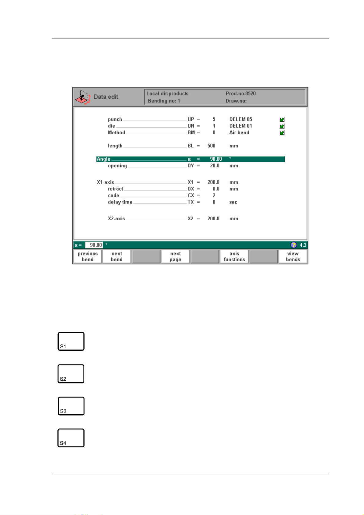
4.2. Bend programming
The parameters of one bend are divided over 2 screen pages.
Delem
4.c
The bend number, product number and drawing number are displayed in the top row on the
screen, the function of the "softkeys" in the bottom row.
Function keys:
previous
bend
next bend select next bend
show
library
next page next page, to select the second page of the parameters to
select previous bend
Open a window with an overview of the tool library.
From here, a tool can be selected. Only available if the
program cursor is positioned on a tool.
be programmed for this bending.
V0606, 4.5
Page 56
Function keys:
axis functions
all bends to the listing of all bends of this program (only possible in
END To end the data prep./edit mode and return to the main
axis functions, to change speed and retract distance of
available axes in the current bend. This function is
machine-dependant.
data-editing).
menu. In the dialogue that appears, enter a new product
number or confirm the existing number.
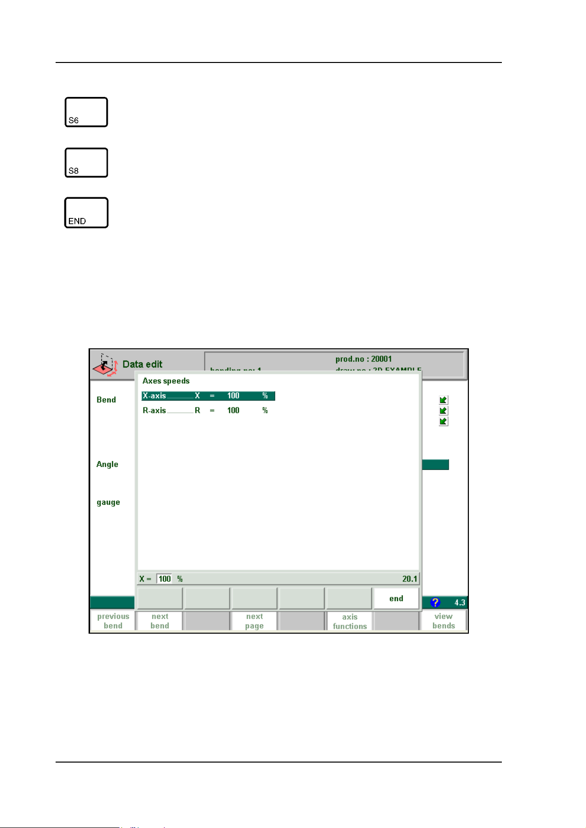
• Axis functions
With this command, speed and retraction of the available axes on the machine can be programmed. This function is machine-dependant. The function is activated by pressing S6 in the
‘Data edit’ screen:
4.d
A pop-up window appears, in which all programmable dimensions for the axes are shown.
Which axes are shown here depends on the machine configuration.
Press the ‘END’ button to leave this window.
Axis speeds
Speed of the selected axis in the current bend. Speed can be programmed in a percentage of the
V0606, 4.6
Page 57
Delem
maximum possible speed.
Retract
Retract distance of the selected axis in the current bend. The distance is always programmed in
millimeters. If the retract distance of the X-axis is altered in this window, the Retract parameter
of the X-axis is automatically adjusted.
• Parameter explanation
Punch . . . . . . . . . . . . . . . . . . . . . . . . . . . . . . . . . . . . . . . . . . . . . . . . . . . .UP
Number of punch in library.
Die . . . . . . . . . . . . . . . . . . . . . . . . . . . . . . . . . . . . . . . . . . . . . . . . . . . . . .UN
Number of die in library.
Program the required tool numbers or press the key to select a tool from the list. Use the
function key ‘Show library’ to check the available tools.
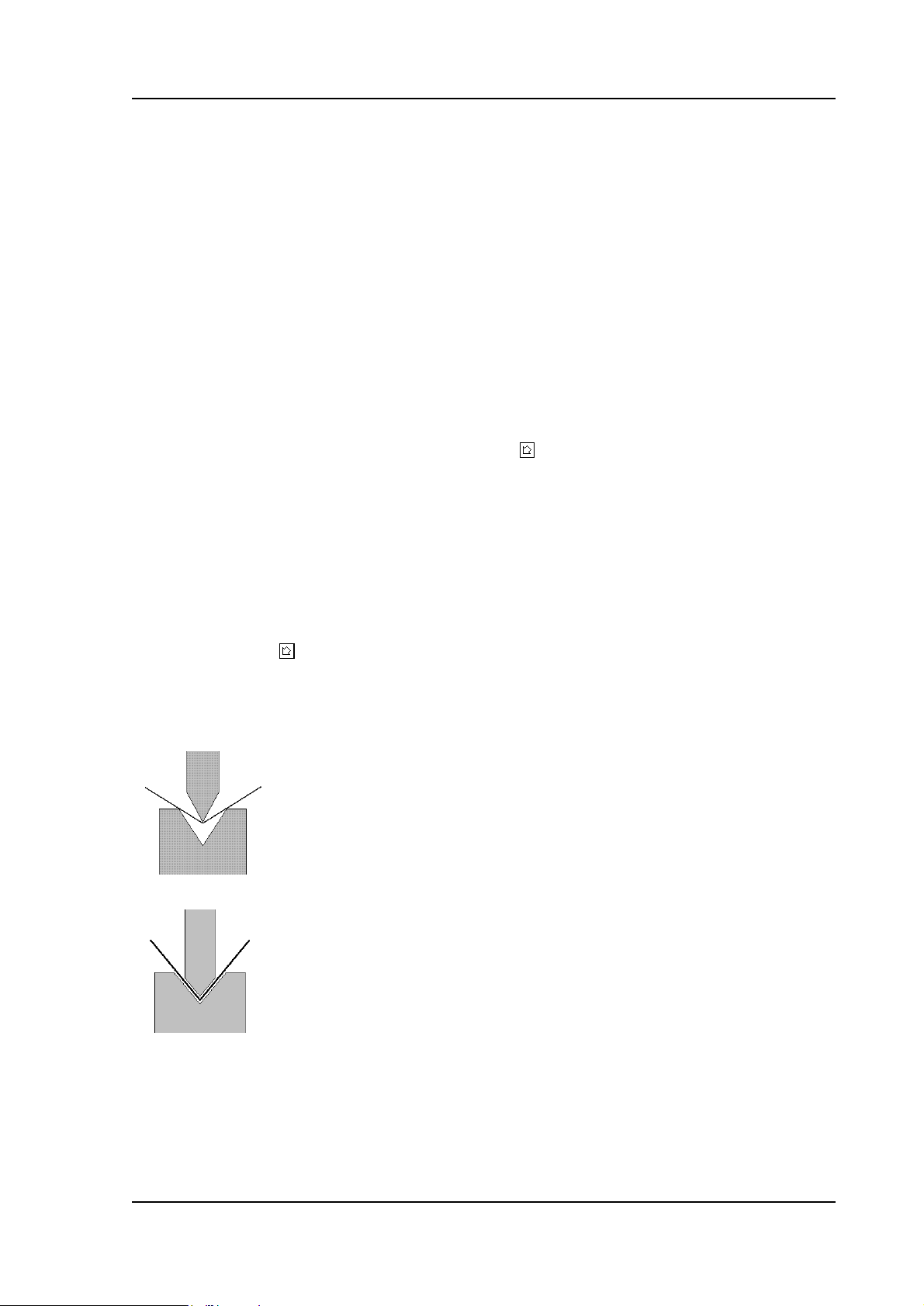
Method. . . . . . . . . . . . . . . . . . . . . . . . . . . . . . . . . . . . . . . . . . . . . . . . . . .BM
Select the required bending method. The control supports 4 methods:
Air bend
Bottoming
Flattening
Flattening & bottoming.
Press the key to select the required setting.
Bend methods:
air bend The sheet is bent to the programmed angle by
bottoming The sheet is bent by squeezing the sheet
bringing the punch to the required depth. The
control calculates the required Y-axis position
to obtain the programmed angle.
between the punch and the die. The control
assumes the bottom of the die as required Yaxis position.
V0606, 4.7
Page 58

flattening The sheet is folded in two. This is possible
after the sheet has been bent into a sharp
angle in a previous bend. The control calculates the precise Y-axis position for this
action: the surface of the die plus twice the
sheet thickness.
Y-axis positioning can be adjusted by programming a 'flattening offset'.
flattening and
bottoming
Note 1:
The flattening bends are shown here with a special flattening punch, but this is not required.
Note 2:
When bottoming operation is selected, the end of bend position of the Y-axis beam is depending on the working tonnage. If however the force is sufficient for the beam to go to the calculated Y-axis end of bend position, the beam stroke will be limited by the position value.
Length . . . . . . . . . . . . . . . . . . . . . . . . . . . . . . . . . . . . . . . . . . . . . . . . . . .BL
Length of plate between tools.
Angle . . . . . . . . . . . . . . . . . . . . . . . . . . . . . . . . . . . . . . . . . . . . . . . . . . . .α
The required angle of this bend. This parameter only appears if angle programming is
selected with the parameter 'Angle sel.' and the bend method is an air bend.
The same as flattening, but now the control
assumes the top of the die as required Y-axis
position. The folded sheet is squeezed
between punch and die.
Bend position . . . . . . . . . . . . . . . . . . . . . . . . . . . . . . . . . . . . . . . . . . . . .Y
The required Y-axis position for this bend. This parameter only appears if absolute programming is selected with the parameter 'Angle sel.' This parameter also appears if the
bend method is bottoming and/or flattening.
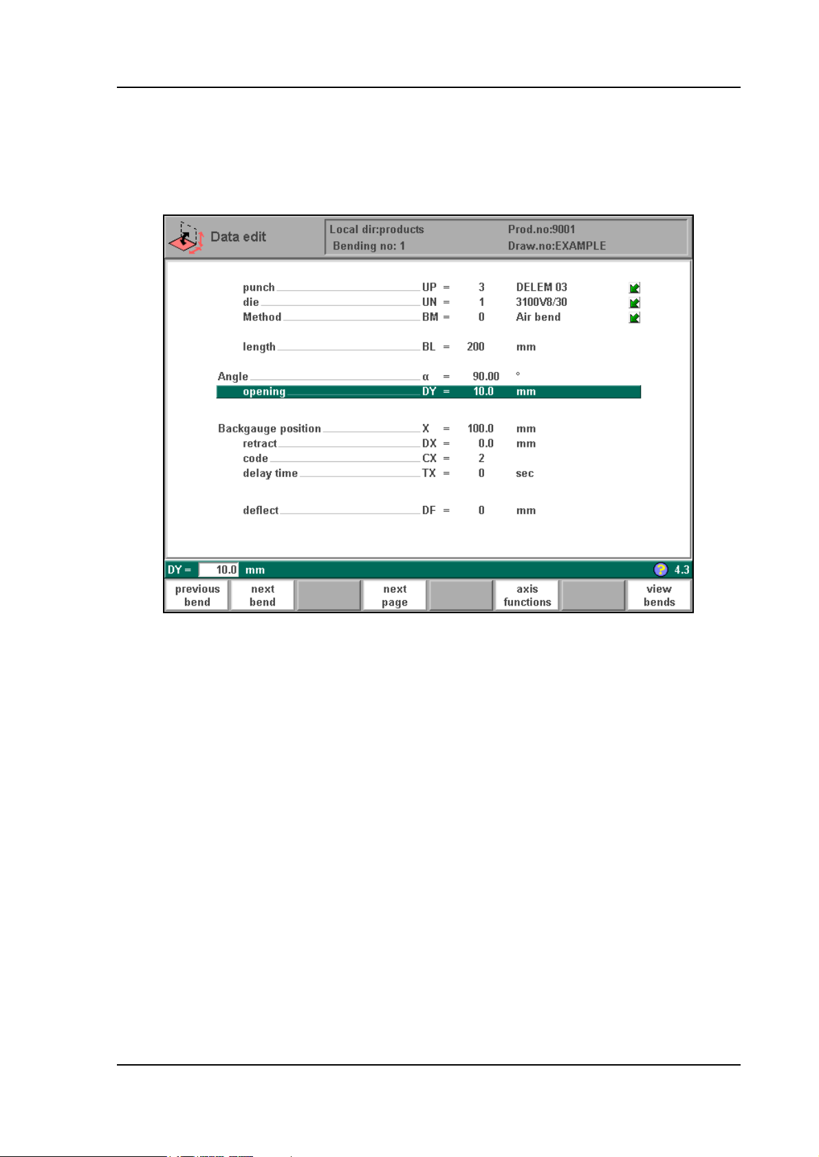
Opening. . . . . . . . . . . . . . . . . . . . . . . . . . . . . . . . . . . . . . . . . . . . . . . . . .DY
This parameter results in a certain gap opening between the punch and the die after the
bend. A positive value is the gap opening above Mute, a negative value below Mute.
When you want to limit the handling time of the product you can program a small positive or a negative value.
Mute . . . . . . . . . . . . . . . . . . . . . . . . . . . . . . . . . . . . . . . . . . . . . . . . . . . .M
Sequence point at which the Y-axis is switched from fast closing speed to pressing speed.
The value programmed here is the distance of the mute point above the plate. By default,
the mute value from the programmed die is used.
Whether or not this parameter is present depends on machine settings.
V0606, 4.8
Page 59
Delem
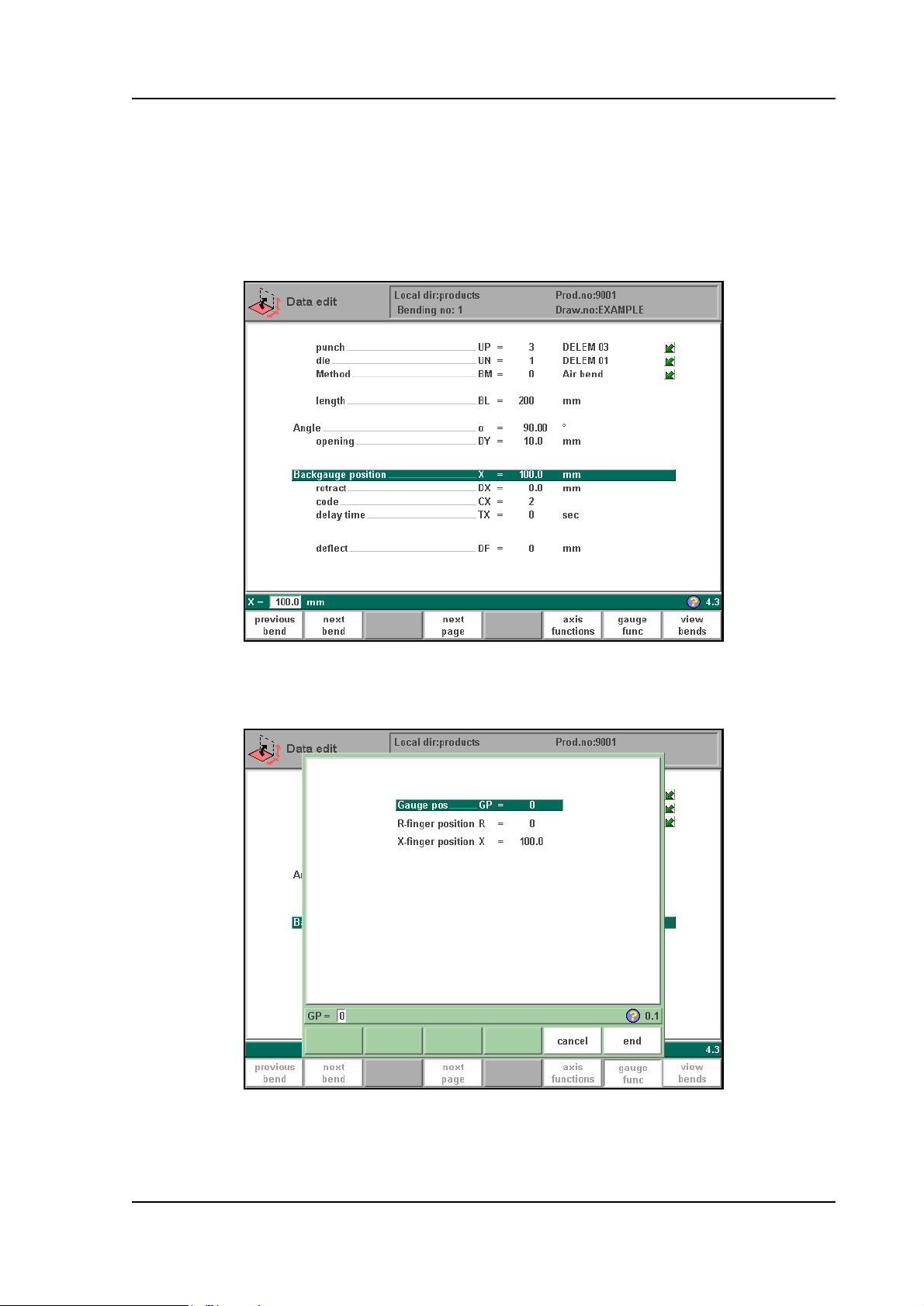
Backgauge position. . . . . . . . . . . . . . . . . . . . . . . . . . . . . . . . . . . . . . . . .X
Backgauge position. When a negative sign is programmed this backgauge dimension is
an incremental dimension. The incremental dimension is subtracted from the actual Xaxis position. Therefore this parameter can also be used as a chaining measure.
Only in case you have a configuration with a R-axis.
The function key (‘gauge func’) appears when you put the cursor bar on this X-axis parameter.
4.e
If you press ‘gauge func’ a window appears with three programmable parameters.
4.f
Gauge pos. . . . . . . . . . . . . . . . . . . . . . . . . . . . . . . . . . . . . . . . . . . . . . . . GP
With this function you can program another ‘gauge position’ for this specific bend. The
V0606, 4.9
Page 60
gauge position (parameter GP) you can program depends on the backgauge dimensions.
Backgauge dimensions are programmed in the menu ‘program constants’.
Default gauge position = 0 (no lay on)
Other possibilities are:
gauge position = 1, lay on first level
gauge position = 2, lay on second level (only possible when number of gauge positions
(GN) = 3)
gauge position = 3, lay on third level (only possible when number of gauge positions
(GN) =4)
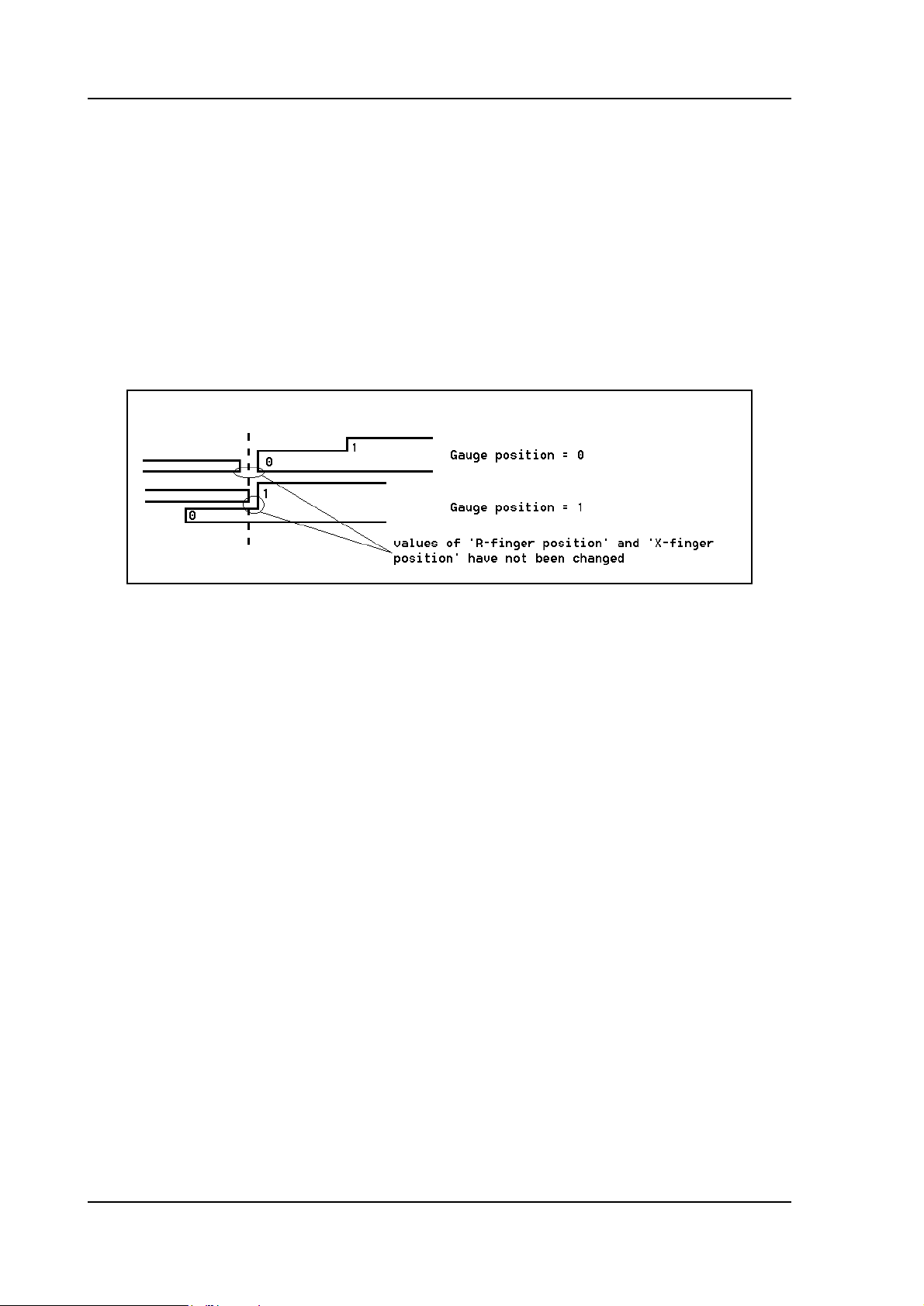
When you program another ‘Gauge position’ the backgauge position changes, but the
gauge position for the plate does not change. This means that the next two parameters
‘R-finger position’ and ‘X-finger position’ remain the same. See also example below.
4.g
R-finger position. . . . . . . . . . . . . . . . . . . . . . . . . . . . . . . . . . . . . . . . . . .R
Default value = the height (R direction) of the gauge position of the plate. This value can
manually be adjusted in this window, if required.
X-finger position. . . . . . . . . . . . . . . . . . . . . . . . . . . . . . . . . . . . . . . . . . .X
Default value = the value in X-direction of the gauge position for the plate. This value
can manually be adjusted in this window, if required.
With ‘END’ you leave the window and the new values have been saved. If you press
‘cancel’ you leave the window without changes.
When you have changed the ‘Gauge position’ then the axes positions in X- and R-direction have also been changed. Therefore the parameters ‘backgauge position...X’ and ‘R-
axis....R’ have been changed. The new values depend on the dimensions of the back-
gauge finger which you have programmed in the menu ‘program constants’. When you
have changed the values of ‘R-finger position’ and ‘X-finger position’, then these
changes are also included.
Retract. . . . . . . . . . . . . . . . . . . . . . . . . . . . . . . . . . . . . . . . . . . . . . . . . . .DX
Retract distance of backgauge during the bending. The "backgauge retract" is started at
the pinching point of the plate.
code . . . . . . . . . . . . . . . . . . . . . . . . . . . . . . . . . . . . . . . . . . . . . . . . . . . . .CX
Programmable parameter which determines when the parameter values for the next
bending will be active. The possibilities are:
0 = Bending number change (step change) at end of decompression (next bend parame-
V0606, 4.10
Page 61

Delem
ters active).
1 = Step change at muting position when the beam moves in opening direction.
2 = Step change at upper dead point.
3 = Step change at upper dead point without movement of any axis and the control goes
to "stop".
4 = Step change if C-input signal becomes active, without movement of the beam. When
you still have a beam movement there will be no retract function of the backgauge performed. See also code 5.
5 = Step change if C-input signal becomes active and the beam is in the upper dead point.
Now you may move the beam and the retract function of the backgauge will be performed.
10= Step change at end of decompression with the Y-axis beam waiting at the pinching
point until the backgauge is at the retract position.
11= Step change at mute position when the beam moves in the opening direction, with
the Y-axis beam waiting at the pinching point until the backgauge is at the retract position.
12= Step change at upper dead point, with the Y-axis beam waiting at the pinching point
until the backgauge is at the retract position.
13= Step change at upper dead point without movement of any axis. The Y-axis beam
will wait at the sheet clamp point until the backgauge is at the retract position. After the
bending with this code, the control goes to "stop".
15= Step change if C-input signal becomes active and the beam is in the upper dead
point. The beam may be moved but not necessarily. The Y-axis beam will wait at the
sheet clamp point until the backgauge is at the retract position.
The not mentioned CX-values have no meaning.
Delay time . . . . . . . . . . . . . . . . . . . . . . . . . . . . . . . . . . . . . . . . . . . . . . . .TX
Programmable delay time before step change (0-30sec)
• Parameter explication (second page)
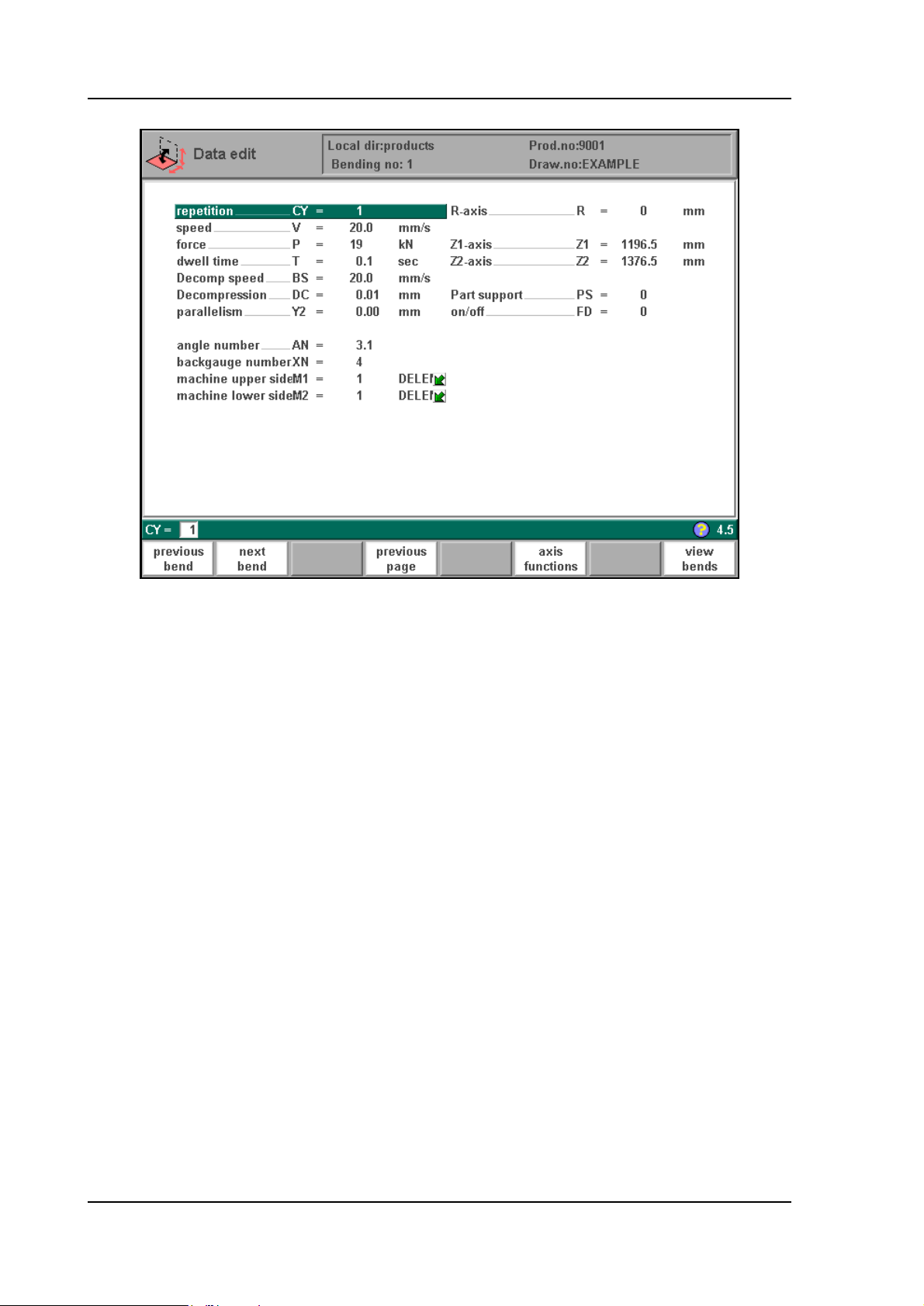
Auxiliary functions of the bending can be programmed on this page.
V0606, 4.11
Page 62
4.h
Repetition . . . . . . . . . . . . . . . . . . . . . . . . . . . . . . . . . . . . . . . . . . . . . . . .CY
0 = bending is skipped
1 through 99 = the number of times this bending will be repeated
Speed . . . . . . . . . . . . . . . . . . . . . . . . . . . . . . . . . . . . . . . . . . . . . . . . . . . .V
Working speed (pressing speed). Initially, the value for this parameter is copied from the
parameter ‘pressing speed’ in the programming constants menu.
Force . . . . . . . . . . . . . . . . . . . . . . . . . . . . . . . . . . . . . . . . . . . . . . . . . . . .P
Max. adjusted tonnage during pressing (auto calculated)
Dwell time . . . . . . . . . . . . . . . . . . . . . . . . . . . . . . . . . . . . . . . . . . . . . . . .T
Holding time of punch at bending point
Decomp speed . . . . . . . . . . . . . . . . . . . . . . . . . . . . . . . . . . . . . . . . . . . . .BS
The decompression speed is the programmable speed which is active during the programmed decompression stroke.
Decompression . . . . . . . . . . . . . . . . . . . . . . . . . . . . . . . . . . . . . . . . . . . .DC
Decompression stroke after bending to release the working pressure
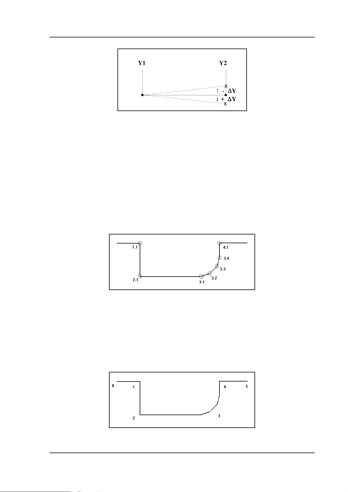
Parallelism . . . . . . . . . . . . . . . . . . . . . . . . . . . . . . . . . . . . . . . . . . . . . . .Y2
Difference of left- and right hand side cylinder (Y1 and Y2). When positive, right hand
side lower. When negative, right hand side higher. The programmed value is active
below the clamping point.
V0606, 4.12
Page 63
Delem
4.i
Auxiliary axis . . . . . . . . . . . . . . . . . . . . . . . . . . . . . . . . . . . . . . . . . . . . .R/Z/Aux.
If you have one or more auxiliary axes (for instance a R-axis, Z-axis or part support) the
parameters of these axes appear here.
Angle number . . . . . . . . . . . . . . . . . . . . . . . . . . . . . . . . . . . . . . . . . . . . .AN
The rank number of this angle, when counted from left to right through the product profile (figure 4.j). The digit before the dot describes this rank number, the digit after the dot
descibes the rank number of this bend in case of a bumping sequence.
In case of a normal angle, the bumping number should always be 1. In the case of a
radius bend, all bends in the bumping sequence should have the same angle number but a
different bumping number. Programming a radius bend in this manner will allow for
bumping correction in the production mode.
4.j
Backgauge number. . . . . . . . . . . . . . . . . . . . . . . . . . . . . . . . . . . . . . . . .XN
A backgauge number refers to a certain spot of the product, that can be placed against the
backgauge during bending. Such a spot is either a product end or an angle. The backgauge numbers in the product are counted from left to right, starting with 0 (see figure
4.k). For each bend you must program here which spot must be placed against the backstop. If the plate must rest on the backgauge finger, add 100 to the XN value. For each
next lay-on position, add another 100 to the backgauge value (200, 300, etc.).
4.k
V0606, 4.13
Page 64

Machine upper side . . . . . . . . . . . . . . . . . . . . . . . . . . . . . . . . . . . . . . . .M1
Machine lower side . . . . . . . . . . . . . . . . . . . . . . . . . . . . . . . . . . . . . . . .M2
The machine number part which is used to make this product and has been drawn in the
machine part library.
Note:
The last 4 parameters are used for graphic simulation of the product in a production mode
(Automatic mode or Step mode). This visualisation does not require a product drawing, only
these parameters must be programmed correctly. Furthermore, the parameter ‘Blank Length’
must be programmed correctly in order to obtain a visualisation.
Note:
After selecting a new bend this will be a copy of the preceding one; you only have to program
those parameters which are different from the preceding bend.
V0606, 4.14
Page 65
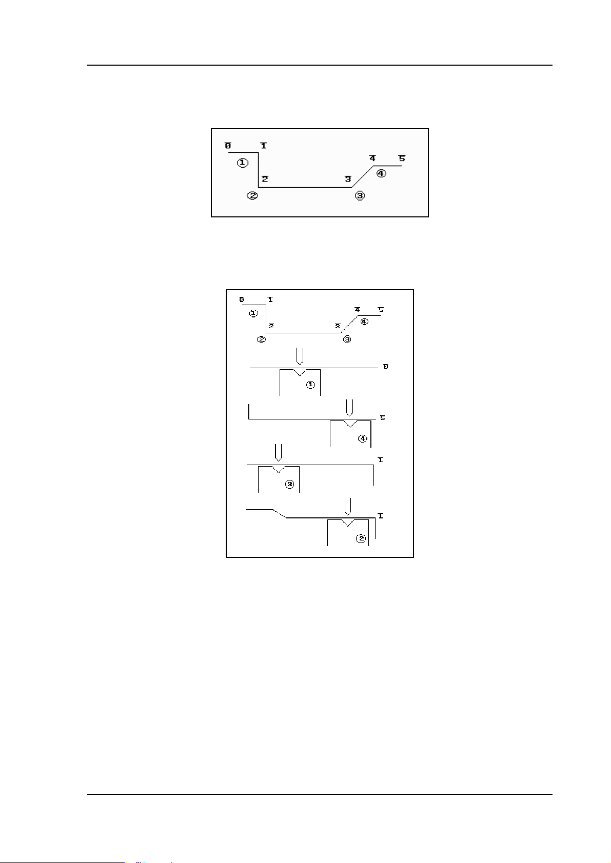
Example:
Product to make:
0 to 5 are possible backgauge positions.
1 to 4 are angle numbers.
Delem
4.l
4.m
Bend Angle (AN) Backgauge (XN)
11 0
24 5
33 1
42 1
V0606, 4.15
Page 66
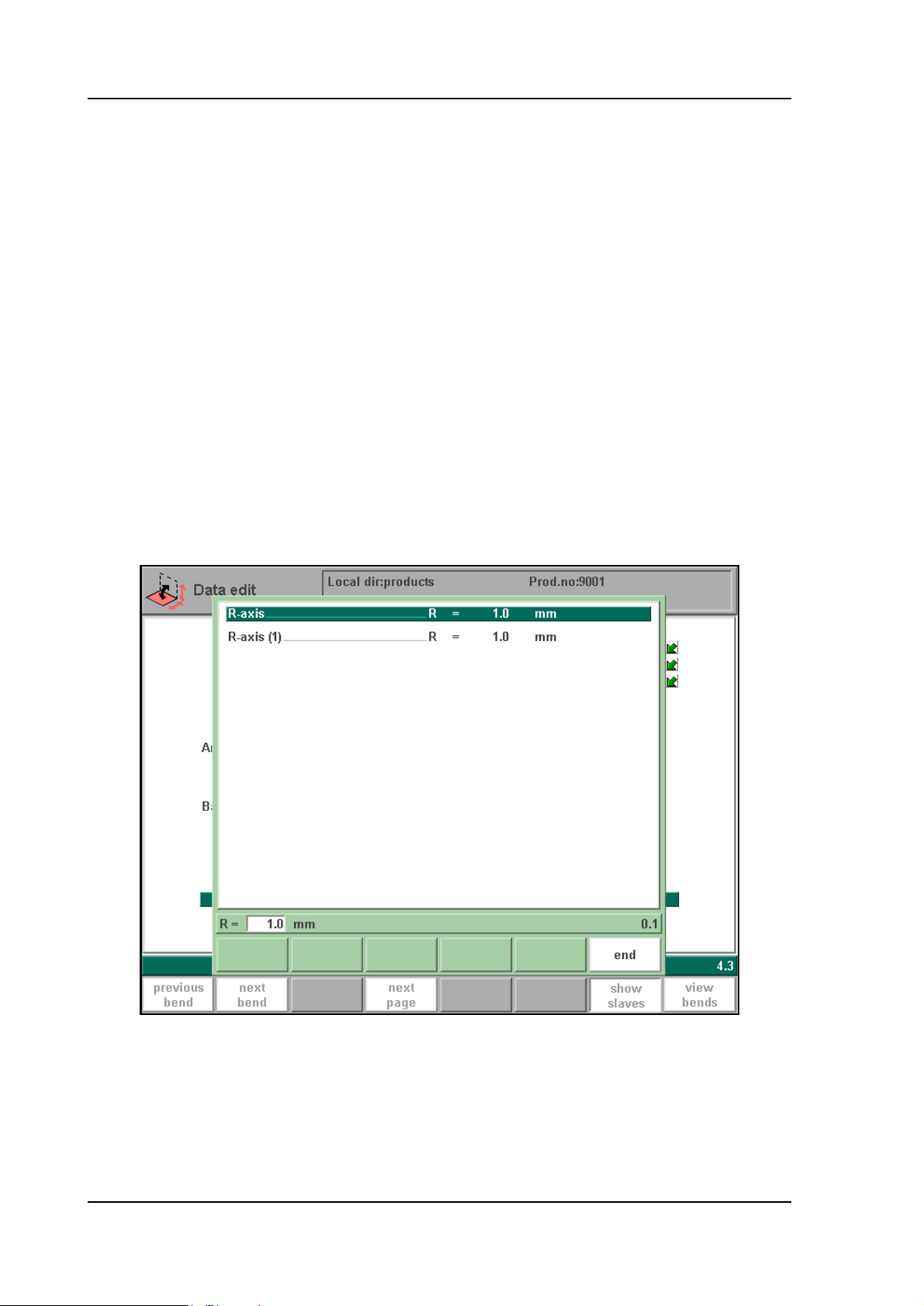
When in, for example, the 1st bend the plate must rest on the backgauge finger, see table below
for programming values.
Bend Angle (AN) Backgauge (XN)
11 100
24 5
33 1
42 1
• Slave axes
Depending on machine settings, it is possible that an auxiliary axis is accompanied by one or
more slave axes that can be programmed individually.
By default, each slave axis follows the position of its master. To progam a different position for
a slave axis, move the cursor to the required axis. The softkey ‘show slaves’ (S7) will appear.
After pressing this key, a new pop-up window appears in which the values of the axis and its
slaves are shown.
4.n
Each slave can be programmed with a different value. If no values are programmed, the slaves
will follow the master. Furthermore, the same minimum and maximum values apply for the
slaves as for the master axis.
This pop-up window is also activated when you move the cursor to an axis parameter and you
type a new value. When this new value is different from the value of the slave(s), the control
V0606, 4.16
Page 67
Delem
will prompt a warning:
"Value will be copied to slave axes. Are you sure?"
If you choose 'yes', the values are copied to the slaves. If you choose 'no', the pop-up window
will be opened automatically. Once you have accepted this copy action with ‘yes’, the value
will be copied to the slaves automatically in the future.
Press END to leave this window.
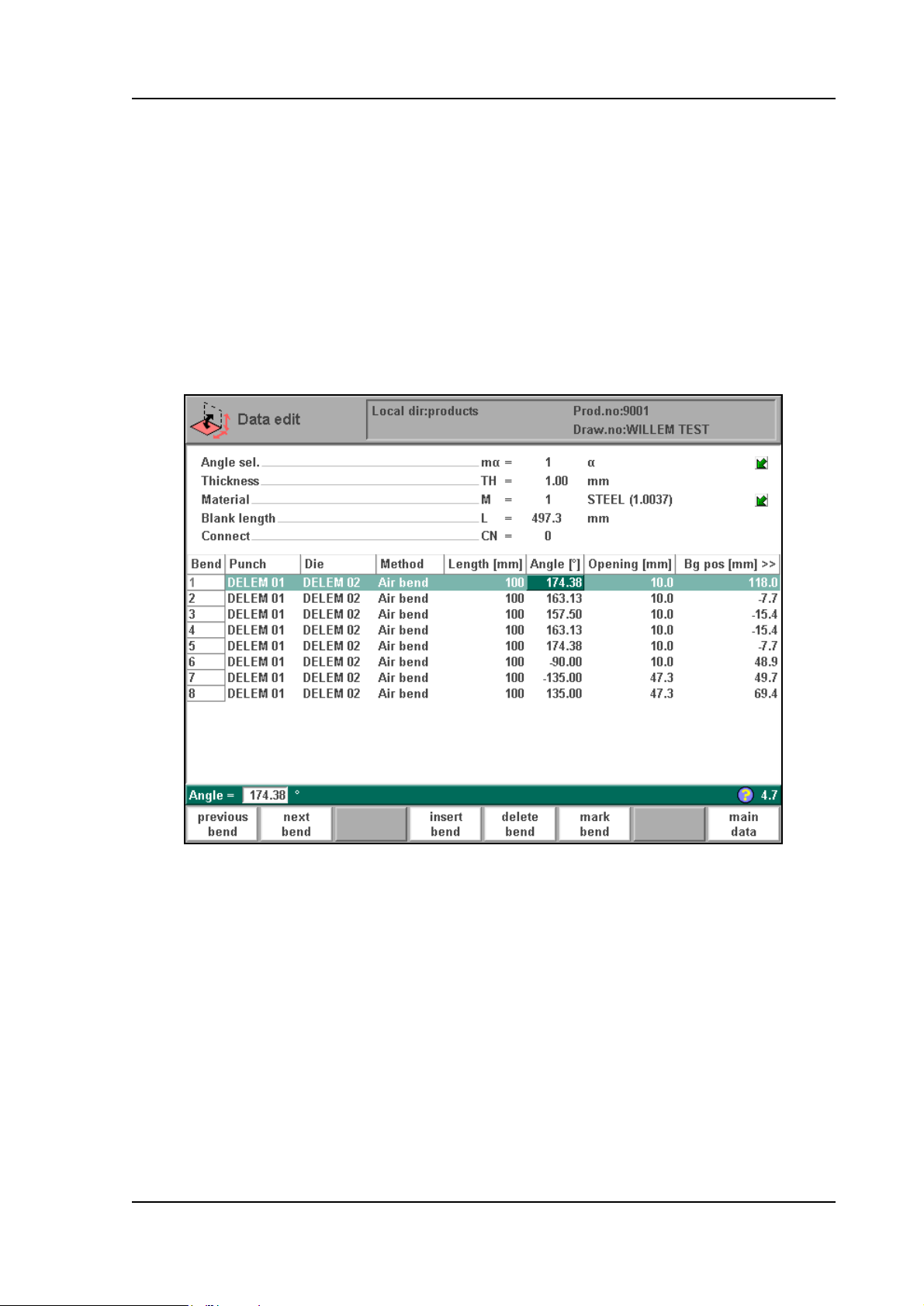
• List of bendings of the prepared program
Pressing this softkey in the data editing mode will result in a complete overview of the bendings programmed. After pushing END the page will be restored from which this page was
selected, with the cursor on the parameter selected before.
4.o
A specific bend can be selected on the screen by putting the highlighted bar on that bend, then
pressing END.
The view is split in two parts. At the top of the parameter screen, the general parameters of the
product are shown. In the main section of the screen, the bend parameters are shown in a
spreadsheet view.
From within this screen, the complete CNC program can be edited. All bend parameters can be
edited within the spreadsheet and bends can be swapped, moved, added and deleted.
V0606, 4.17
Page 68

Function keys:
prev. bend To go to a previous bend when available.
next bend To go to a next bend when available.
insert bend To insert a new bend between one of the bends, select
with the cursor keys first the bend after which a bend
must be inserted. Then push S1 for inserting, results in a
new bend which is a copy of the previous one.
delete bend To delete a bend of the program first select this bend with
the cursor (highlighted bar).
mark bend Mark the current bend, in order to prepare it for another
action, like move or swap. See description below.
END Back to bend parameters.
When a bend has been marked with the function key 'mark bend' several other function keys
become available:
Function keys:
move bend With this command the bend sequence can be edited in
this screen.
swap bends Let two bends exchange places.
abort mark Remove the mark from the currently marked bend.
Move bend
In the spreadsheet overview of the bendsequence, it is possible to change the order of bends
simply by moving a bend to another place. Use the arrow keys to move the cursor to the bend
V0606, 4.18
Page 69
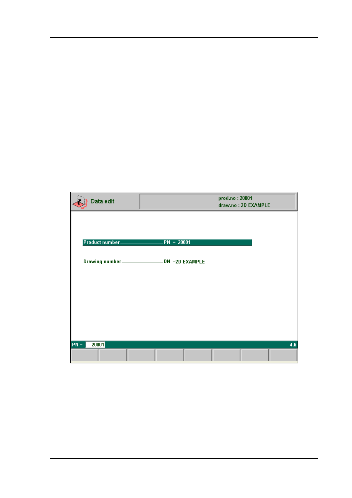
Delem
that must be replaced. Then press the button ‘mark bend’ and the bend is highlighted. Now use
the arrow key to move to the right place in the sequence. When the correct bend number is
highlighted, press ‘move bend’. The bend will be inserted on the current place.
Swap bends
With this command, two bends can change place in the bend sequence. Move the cursor to one
of the required bends and press the ‘mark bend’ button. Then move the cursor to the bend with
which it must be swapped and press ‘swap bends’. If for any reason the action must be cancelled, press the softkey ‘abort mark’ during the procedure.
A bend is no longer marked when the mark is aborted, when an action is finished or when this
menu is left.
• Ending data preparation/data editing
After pushing the END key in the Data edit screen, a new page with product number and drawing number appears.
4.p
At this page the program number and the drawing number must be given to the new prepared
program, or can be changed in the edit mode.
If either way the number is changed into an existing product number, a warning appears that
this product already exists. You are asked whether to replace that existing product with the new
product or not. If you press ‘yes’ (S4), the existing product is replaced by the current product.
If you press ‘no’ (S5), you have to enter a new number.
After typing the product number, press ‘enter’ to confirm it and to return to the main menu.
V0606, 4.19
Page 70

4.3. Special edit function
When a new program has been made and several tests are required, the operator can switch
from "editing"-mode directly to the "auto"-mode and vice versa by pressing the particular
mode buttons.
When in "data editing" a specific bending is selected, the operator can now select the "automatic mode" or "step by step mode".
In case one wants to edit the program, the edit mode can be selected directly with the programming key. In this way many key operations are saved in order to make program changes
quickly.
Note:
This special edit function can not be used with connected programs.
4.4. Edit notes
After changing program data in the menu ‘Data edit’ the control will not automatically calculate:
1Force
2 Decompression
3 Crowning device setting
4 Z-axis position offset
5 X-axis position correction
Parameters 1 through 4 are only automatically recalculated if the parameter Auto computa-
tions edit (see the menu ‘program constants’) has been activated (value = 1).
Parameter 5 is only automatically recalculated if the parameter Bend allowance (see the menu
‘program constants’) has been activated (value =1). Additional corrections on the X-axis position can be made with the parameter corr.X (per bend) and G-corr.X (for all the bends of the
active program) in the automatic and step-by-step mode.
For detailed information upon both parameters see the chapter about Automatic mode and
Step-by-step mode.
There is one exception: when the parameter bendmethod is changed the “force” and “Decompression” will be adjusted automatically.
Also you may find that the graphical simulation will not go properly when you have changed
tools and/or X-axis dimensions.
V0606, 4.20
Page 71
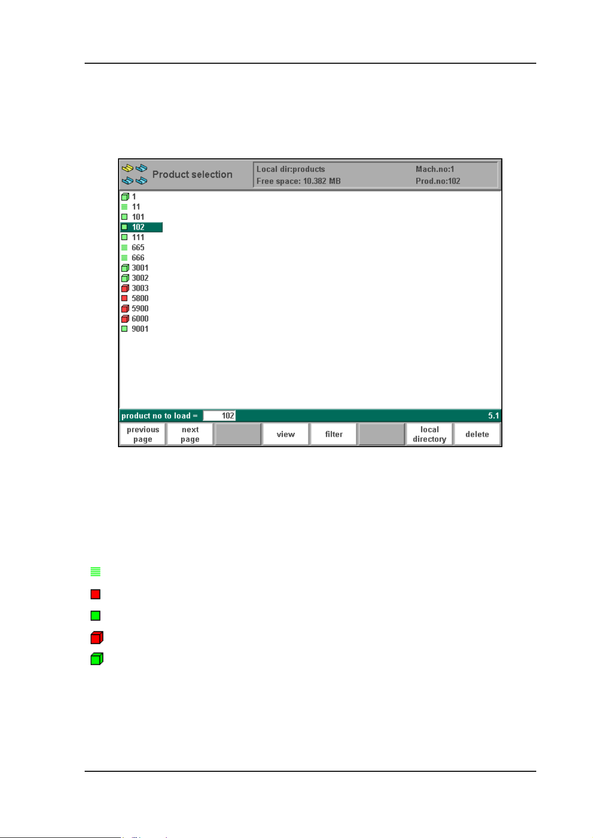
5. Product selection
5.1. Introduction
This chapter describes the menu ‘product selection’.
Delem
5.a
In the "product selection" overview, a listing of all the programs which are present in the main
memory is given. In the enter field a new product number or drawing number can be entered to
select (load) a new program from the mainmemory. The loaded product can directly be executed in the automatic mode. Each item in the list consists of a symbol and a number. The
number is simply the product number, the symbol can have the following meanings:
the product has a CNC program, there is no drawing
(red)
(green)
(red)
(green)
the product consists of a 2D drawing, there is no CNC program
the product has a 2D drawing and a CNC program
the product consists of a 3D drawing, there is no CNC program
the product has a 3D drawing and a CNC program
V0606, 5.1
Page 72
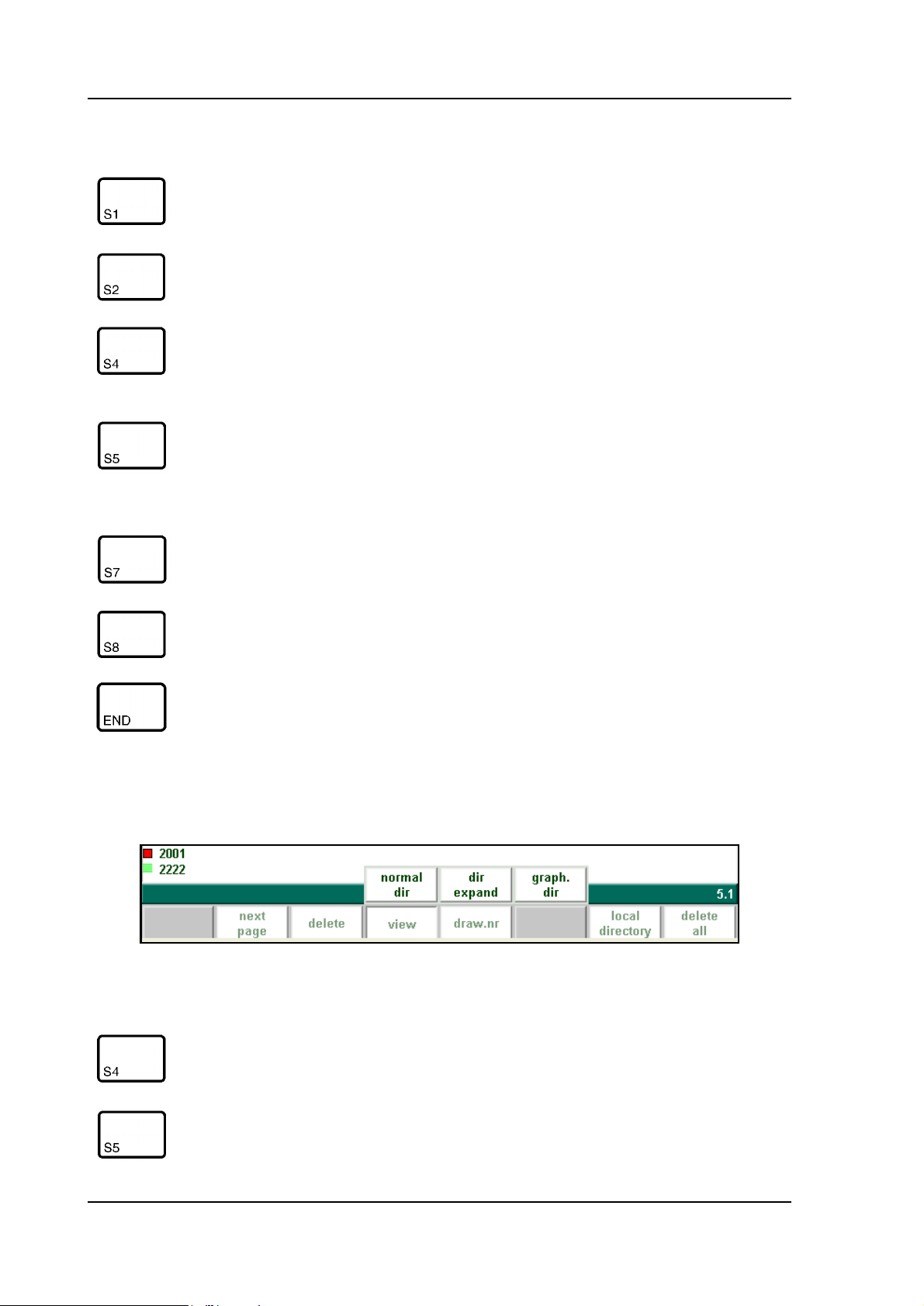
Functions keys:
previous
page
next page Next page with products overview
view Button to select one out of three possible viewing modes:
filter Function key to open a new button bar with extra function
local directory
delete Delete programs from the memory
Previous page with products overview
- normal dir.
- dir. expand
- graph. dir.
keys for product selection functions:
- prod. nr.
- draw nr.
- search
Via ‘local directory’ you get an overview of the manually
created product directory structure.
End the product selection
When the function key ‘View’ has been pressed a new, temporary button bar appears with
additional softkeys:
5.b
Function keys:
normal dir. Select a normal view of the product collection. This is the
standard setting.
dir. expand To obtain a detailed overview of the product collection,
with additional information for each product
V0606, 5.2
Page 73
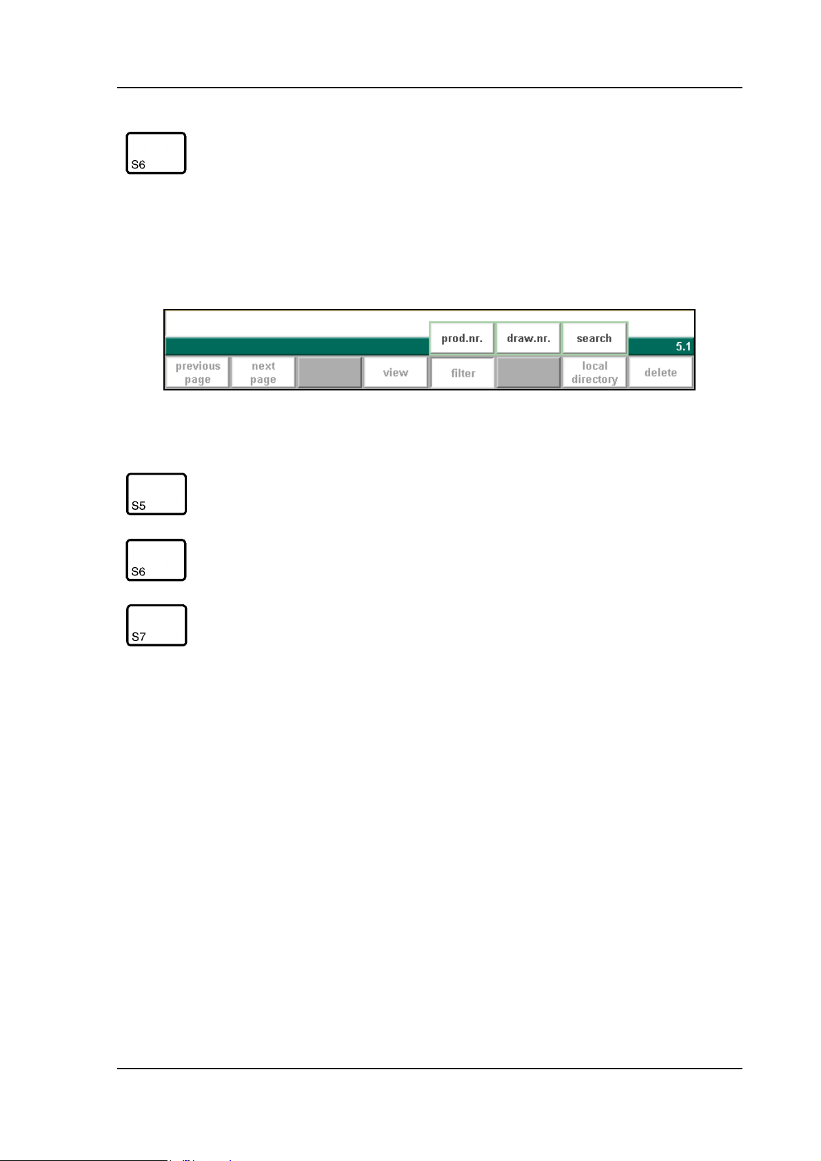
Delem
Function keys:
graph. dir. Select a graphical overview of the product collection.
The other function keys cannot be selected here, until one of these three function keys has been
chosen. The temporary bar will disappear again.
When the function key ‘filter’ has been pressed a new, temporary button bar appears with additional softkeys:
5.c
Function keys:
prod. nr. Products are shown in columns with symbols and product
number, they are sorted on product number. This is the
default view.
draw nr. If this key is pressed in this screen the list of products is
automatically sorted on the alphabetical order of drawing
numbers.
search Start the search function, to search for a specific name or
number.
V0606, 5.3
Page 74
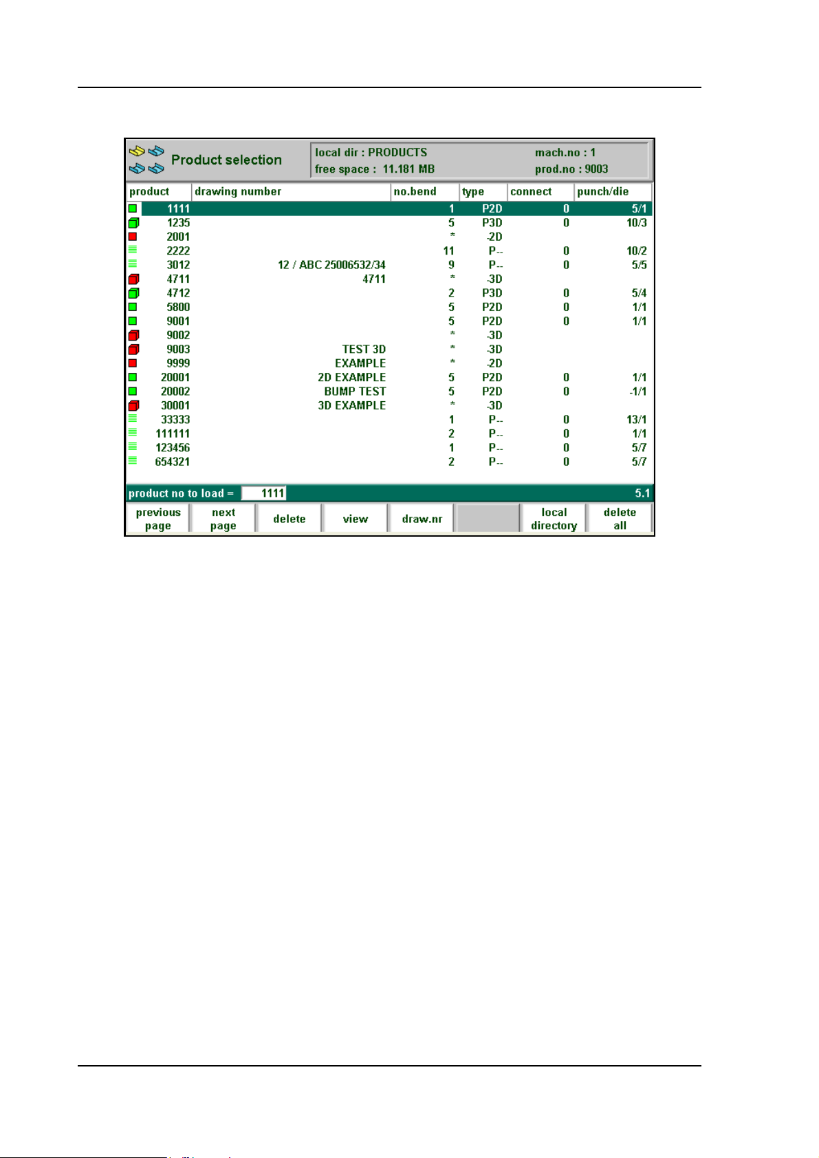
• Expanded directory
5.d
Expanded directory, a product overview which contains the following information for each
product is displayed:
• Product number
• Drawing number
• Number of bends
• Type indication
• Connected program (0 = no connection)
• Selected tools (in first bend)
• Search function
When the search function is selected, you can search for products with a certain number or
name. At the bottom of the screen the text “search to load” is displayed, to indicate that you
may enter a string the control will search for. You can either enter a complete name or number
or only a part of it. Press ‘enter’ to start a search.
If you enter part of a name and this part occurs in several product names, the control will show
all product names that contain the given characters. It is also possible to enter a combination of
name and number.
V0606, 5.4
Page 75
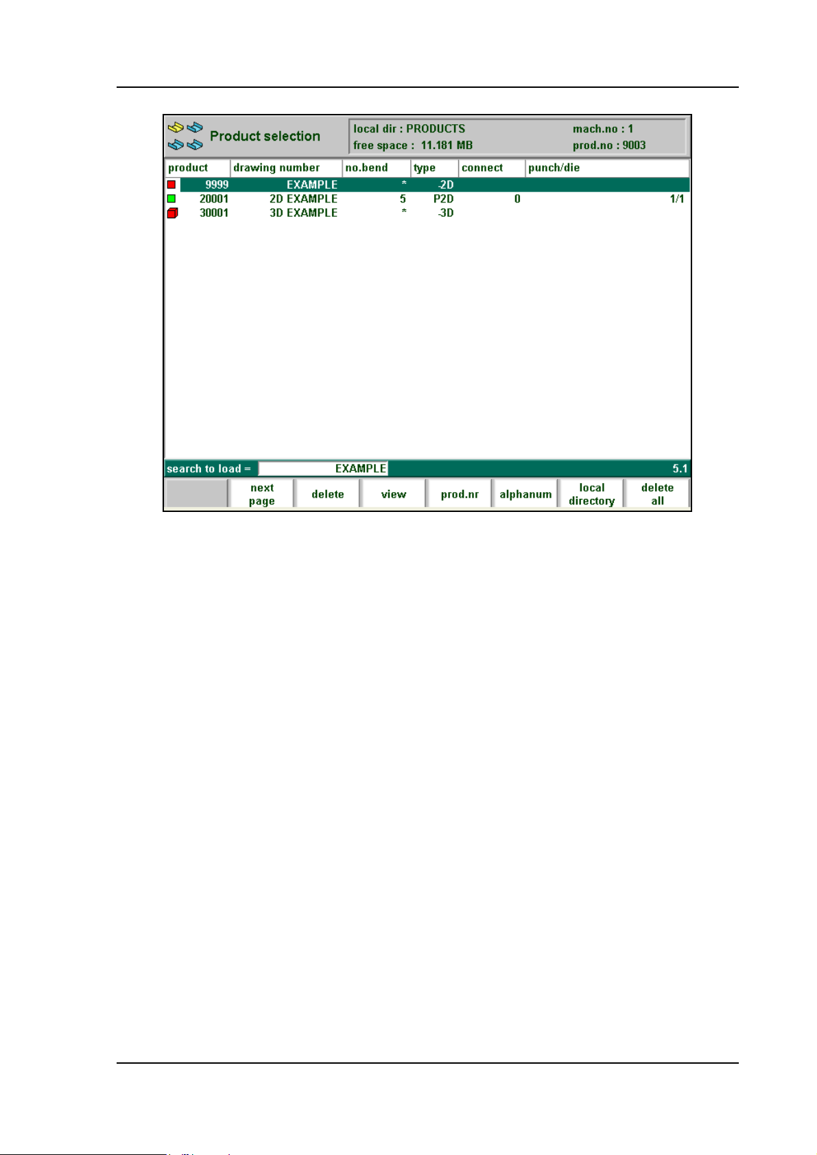
Delem
5.e
V0606, 5.5
Page 76
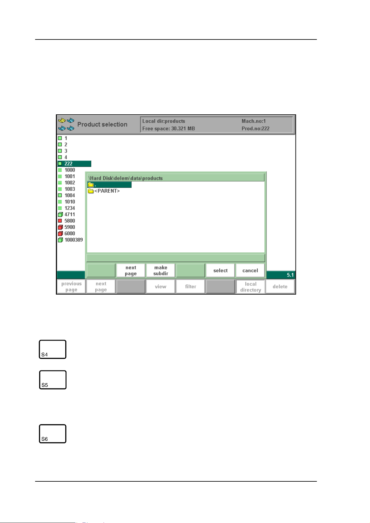
5.2. Directories
Bend programs on the control can be stored in different directories. The active local directory
name is displayed in the header.
When the function key ‘local directory’ has been pressed in the product menu, a new window
appears with an overview of directories on the control.
Function keys:
5.f
make subdir Add a new subdirectory. The name of the subdirectory can
be any alpha numeric string of maximal 8 characters.
(Avoid the use of slashes ‘/’).
remove subdir
select To select the directory on which the cursor is placed.
Delete a subdirectory. If the subdirectory is not empty, the
control returns the message ‘UNABLE TO REMOVE
DIRECTORY’. An empty subdirectory is deleted without
warning. The default directory “PRODUCTS” can also be
deleted. When all the subdirectories have been removed
the control creates automatically the default directory
V0606, 5.6
Page 77
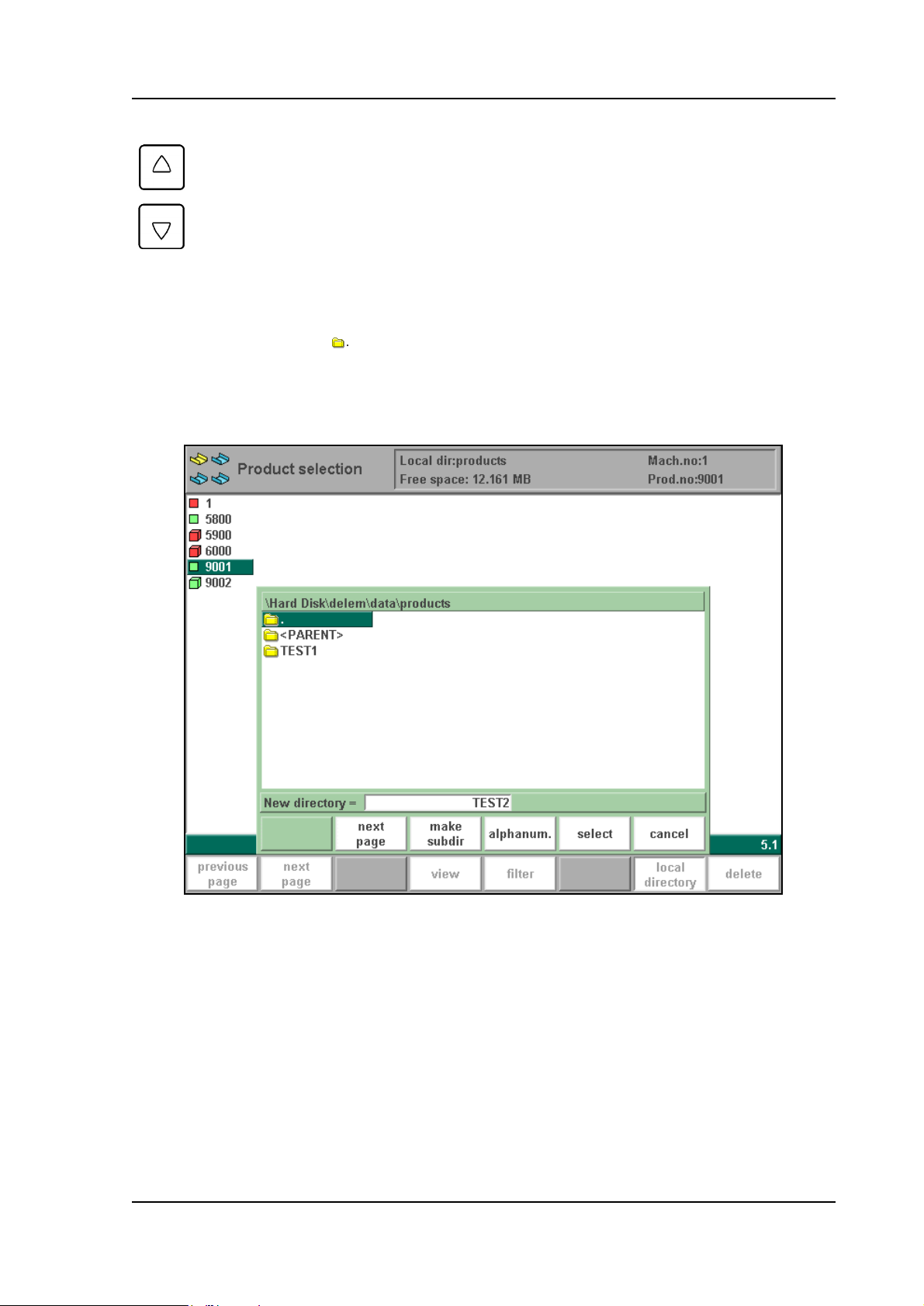
Function keys:
Delem
Cursor key
Up/Dn
Use the function key 'select' to make a subdirectory active. Press ENTER to look inside a subdirectory. To move up, go to the <PARENT> map and press ENTER. To select the directory
you are currently in, go to and press ‘select’.
In this menu it is also possible to remove existing subdirectories (only an empty one) and to
make new subdirectories. Press ‘make subdir’ and enter the new name. Subdirectories are
called subdirectories because these directories reside under the local directory ‘\PRODUCTS’.
Select another subdirectory.
5.g
It is not possible to copy products from one subdirectory to another subdirectory. A product
must be restored in a subdirectory via the menu ‘product backup’. You cannot change the name
of the subdirectory.
When you leave the product selection menu the control remembers the active subdirectory and
the active product (if a product was selected) until another directory or product is selected.
V0606, 5.7
Page 78

V0606, 5.8
Page 79
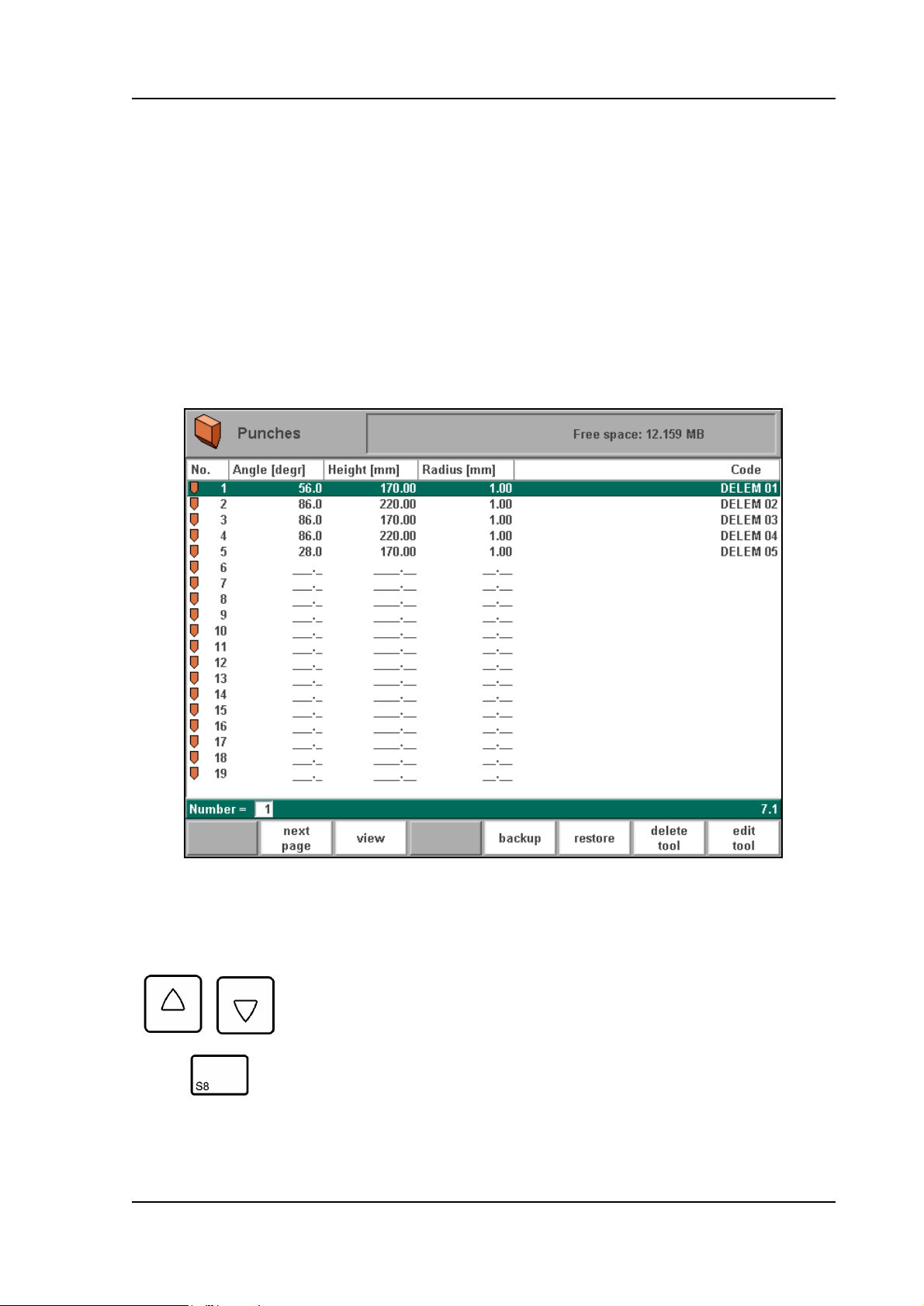
Delem
6. Programming of tools
6.1. Introduction
This chapter describes the programming of the tools and machine shapes.
6.2. Programming of Punches
6.2.1. The punch menu
The programming of punches is started by choosing ‘Punches’ in the main menu. The punch
profile can be created with help of the programming facilities of the control.
6.a
A listing of punches programmed into the memory is given.
The punch is selected by moving the highlighted cursor
bar resulting in the drawing of the upper tool.
V0606, 6.1
Page 80
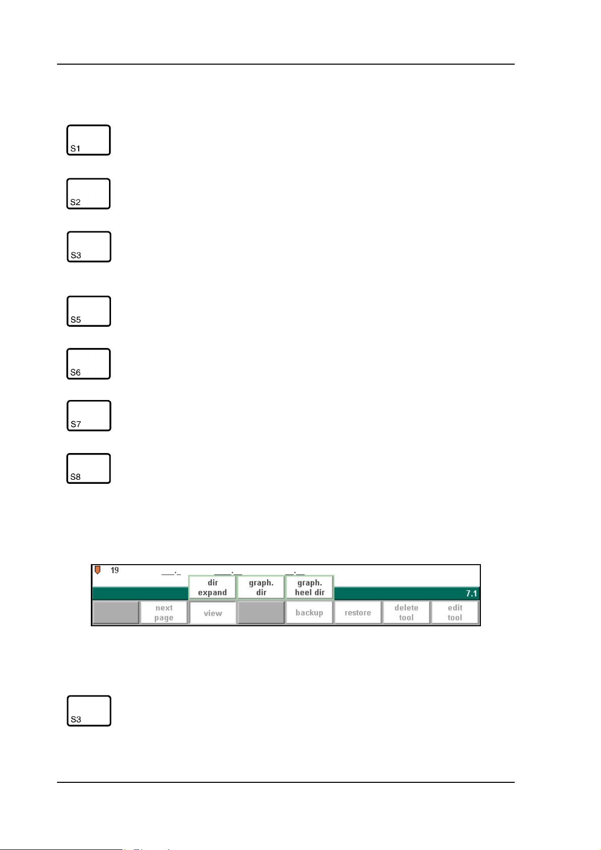
Function keys:
previous
page
next page To select the next page within the several pages of the
view Button to select one of the possible viewing modes:
backup Save tools from library to disk.
restore Load tools from disk into the control.
delete tool Remove tool from library.
To select a previous page within the several pages of the
punch library.
punch library
- dir. expand
- graph. dir.
- graph. heel dir.
edit tool To edit the tool drawing or edit the punch data.
When the function key ‘View’ has been pressed a new, temporary button bar appears with
additional softkeys:
6.b
Function keys:
dir. expand Select the normal view of the tool collection. This is the
standard setting.
V0606, 6.2
Page 81
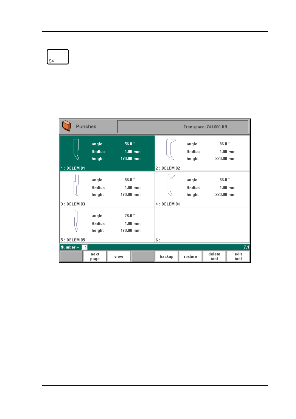
Delem
Function keys:
graph. dir To get a graphical overview of the tools as available in
the library including main dimensions of the tool.
The other function keys cannot be selected here, until one of these three function keys has been
chosen. The temporary bar will disappear again.
• Graphical directory
6.c
V0606, 6.3
Page 82
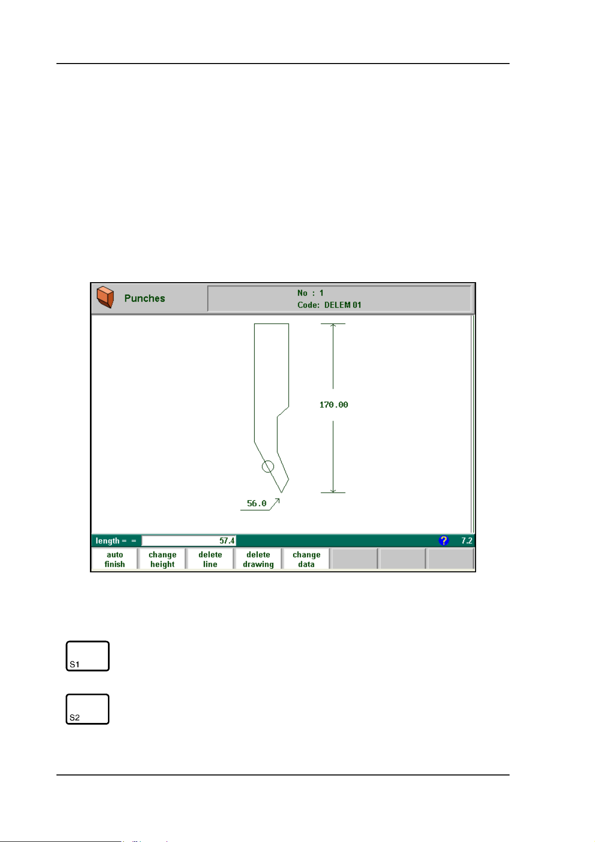
• Edit punch drawing
The display starts prompting the initial dimensions of your punch in the case of programming a
new punch.
Height . . . . . . . . . . . . . . . . . . . . . . . . . . . . . . . . . . . . . . . . . . . . . . . . . . .H
The height of the tool. Important: this height value will be used in bend depth calculation.
Angle . . . . . . . . . . . . . . . . . . . . . . . . . . . . . . . . . . . . . . . . . . . . . . . . . . . .a
The angle of the punch tip.
Hereafter you can enter angle and length dimensions as in the product drawing facilities.
Function keys:
V0606, 6.4
6.d
auto finish Finishing the tool outline to the top of the tool automati-
cally
change
height
To change the height dimension of the tool
Page 83
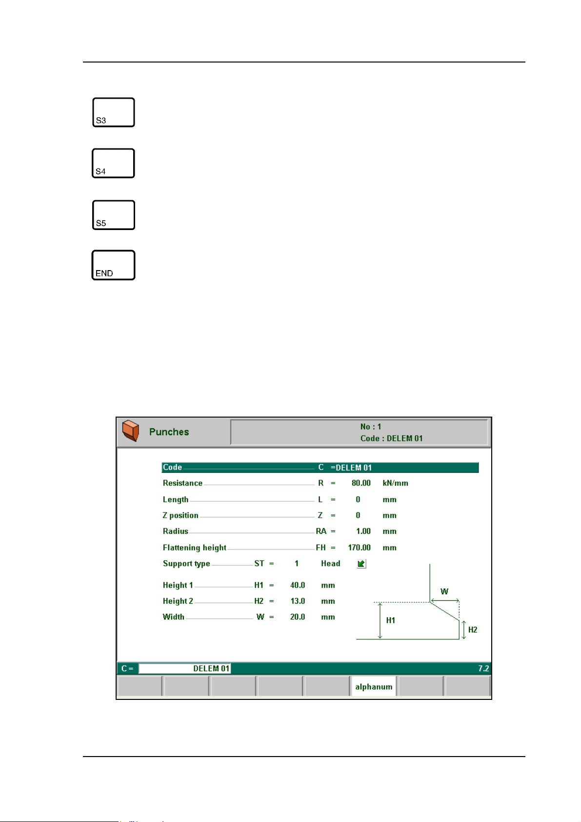
Function keys:
Delem
delete line To delete a line segment
delete
drawing
change
data
To delete the complete tool from the library
To change specific tool data and code (see section 6.2.2.)
To return to the directory overview
• Drawing orientation of the punch on the screen
The right hand side of the tool is the backgauge side.
The bottom point of the punch will be placed on the center line of the press brake shape.
6.2.2. Specific Punch Data
6.e
V0606, 6.5
Page 84
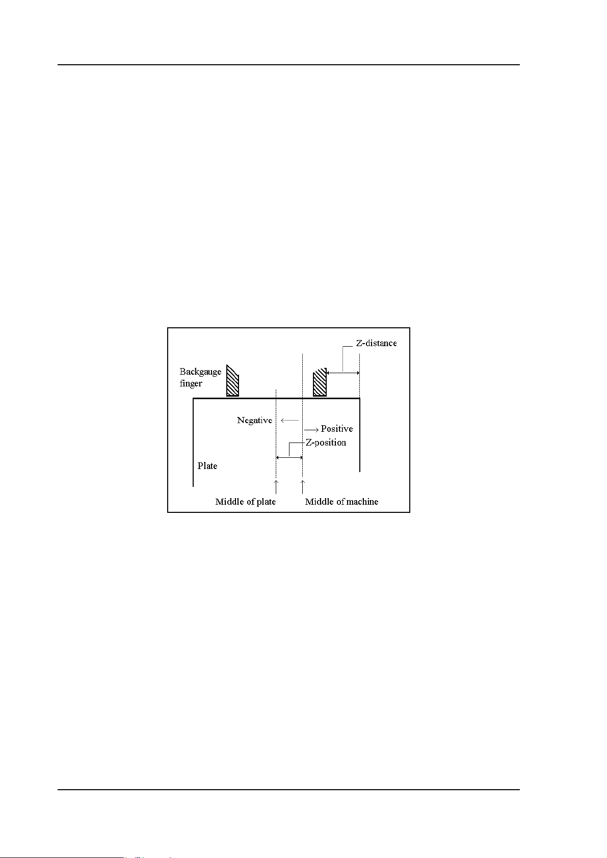
Code. . . . . . . . . . . . . . . . . . . . . . . . . . . . . . . . . . . . . . . . . . . . . . . . . . . . .C
Alphanumeric tool name with a maximum of 20 characters
Resistance . . . . . . . . . . . . . . . . . . . . . . . . . . . . . . . . . . . . . . . . . . . . . . . .R
Maximum allowable force on punch in kN/mm
Length . . . . . . . . . . . . . . . . . . . . . . . . . . . . . . . . . . . . . . . . . . . . . . . . . . .L
Length of the punch to be used
Z-position . . . . . . . . . . . . . . . . . . . . . . . . . . . . . . . . . . . . . . . . . . . . . . . .Z
Offset position of the middle position of the punch in relation to the middle of the press
brake.
(Default value is 00 mm)
In case automatic Z-axis are used the Z-axis value is computed from the: plate length, Zdistance (menu ‘Program constants’) and Z-position.
Top vi e w
6.f
Radius . . . . . . . . . . . . . . . . . . . . . . . . . . . . . . . . . . . . . . . . . . . . . . . . . . .RA
The radius of the punch.
This parameter has to be used as selection criterium, the value will not be used in computation formulas.
Flattening height . . . . . . . . . . . . . . . . . . . . . . . . . . . . . . . . . . . . . . . . . .FH
The flattening height need to be programmed when you make use of a special flattening
punch to flatten your product.
The programmable height is used to calculate the Y-axis value in case of "flattening". The
default-value for this parameter is the standard tool height, which is already programmed.
Every time that this standard height is changed, the flattening height will be made equal to this
tool height (due to safety reasons). See figure 6.g.
The total toolheight will be used to calculate the speed change point mute and the flattening
height will be used to calculate the end position of the Y-axis beam to flatten the product. The
V0606, 6.6
Page 85
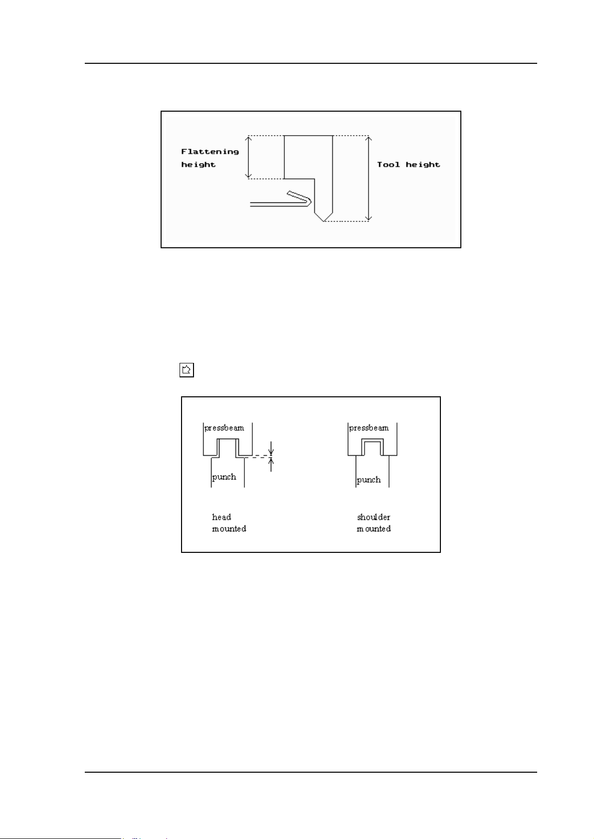
Delem
calculation will take 2x sheet thickness into account. Also you can program a flattening offset
in the menu ‘Program constants’. This value will be added to the value of 2x sheet thickness.
6.g
Support type . . . . . . . . . . . . . . . . . . . . . . . . . . . . . . . . . . . . . . . . . . . . . .ST
Switch parameter, to account for differently mounted punches. Such punches could
cause inaccuracies in the tool height and the resulting Y-axis position. The control makes
a distinction between two settings, 'head mounted' and 'shoulder mounted'.
0 = shoulder mounted (default setting)
1 = head mounted
Press the key to select the required setting.
6.h
If 'shoulder mounted' is chosen, the Y-axis position is calculated from the standard tool height.
This is the default setting.
If 'head mounted' is chosen, a correction is made for Y-axis computation.
V0606, 6.7
Page 86
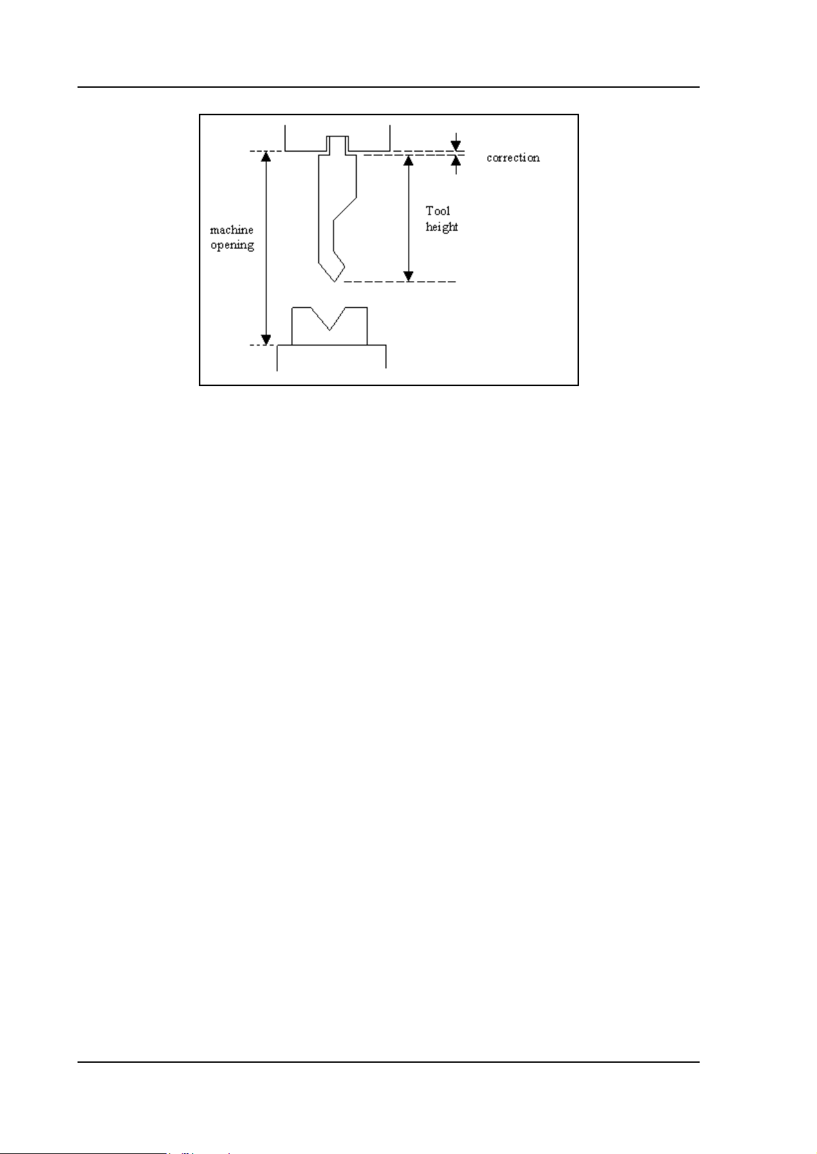
6.i
V0606, 6.8
Page 87
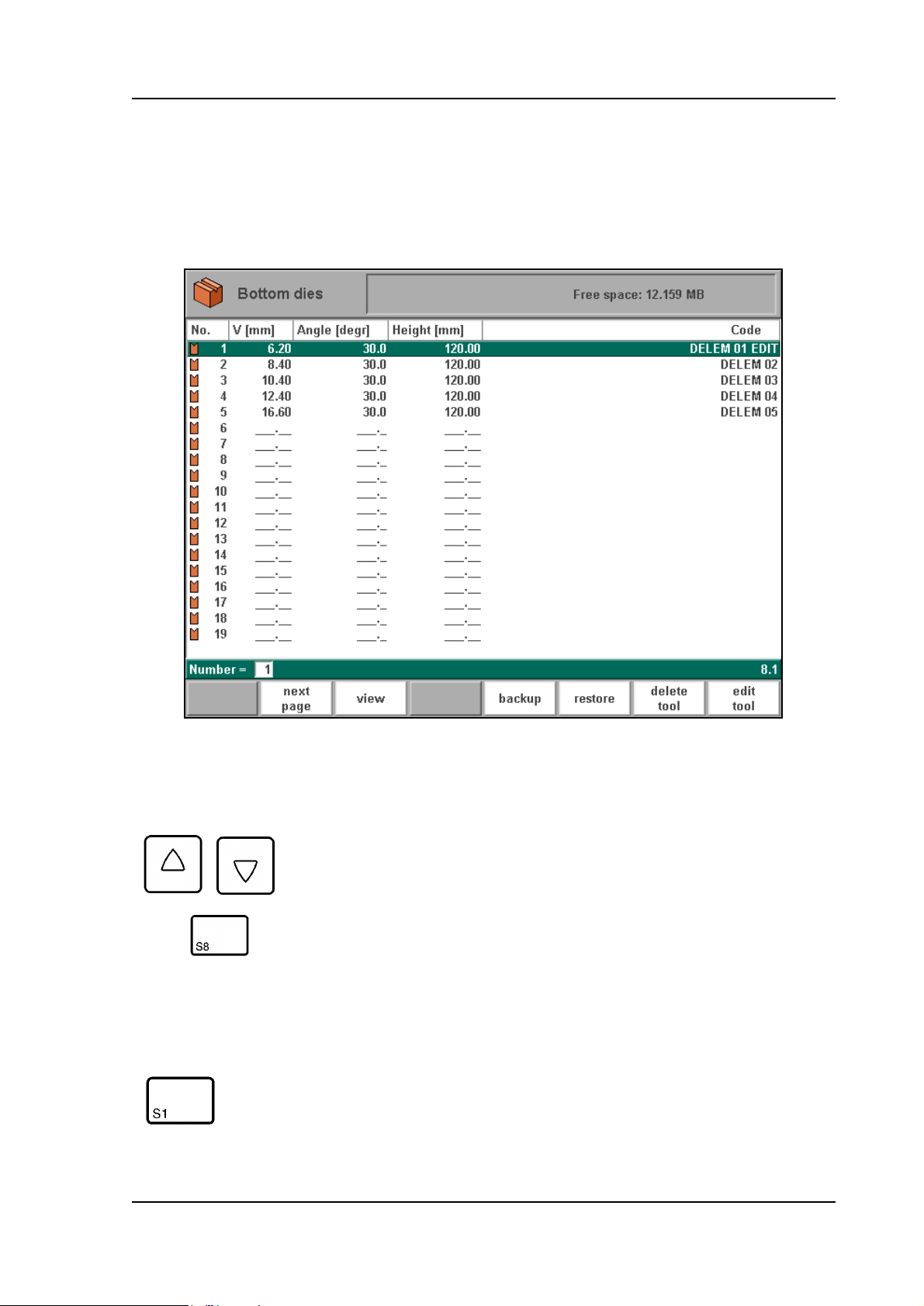
Delem
6.3. Programming of bottom dies
6.3.1. The die menu
The programming of dies is started by choosing ‘Bottom dies’ in the main menu.
A listing of the programmed dies is given.
A die can be selected with the highlighted cursor.
Function keys:
previous
page
To select a previous page within the several pages of the
available dies in the library.
6.j
V0606, 6.9
Page 88
Function keys:
next page To select the next page within the several pages of the die
library.
view Button to select one of the possible viewing modes:
- dir. expand
- graph. dir.
backup Save tools from library to disk.
restore Load tools from disk into the control.
delete tool Remove tool from library.
edit tool To edit the tool drawing or check the die data.
To return to the program menu.
When the function key ‘View’ has been pressed a new, temporary button bar appears with
additional softkeys:
6.k
Function keys:
dir. expand Select the normal view of the tool collection. This is the
standard setting.
graph. dir To get a graphical overview of the tools as available in
the library including main dimensions of the tool.
V0606, 6.10
Page 89
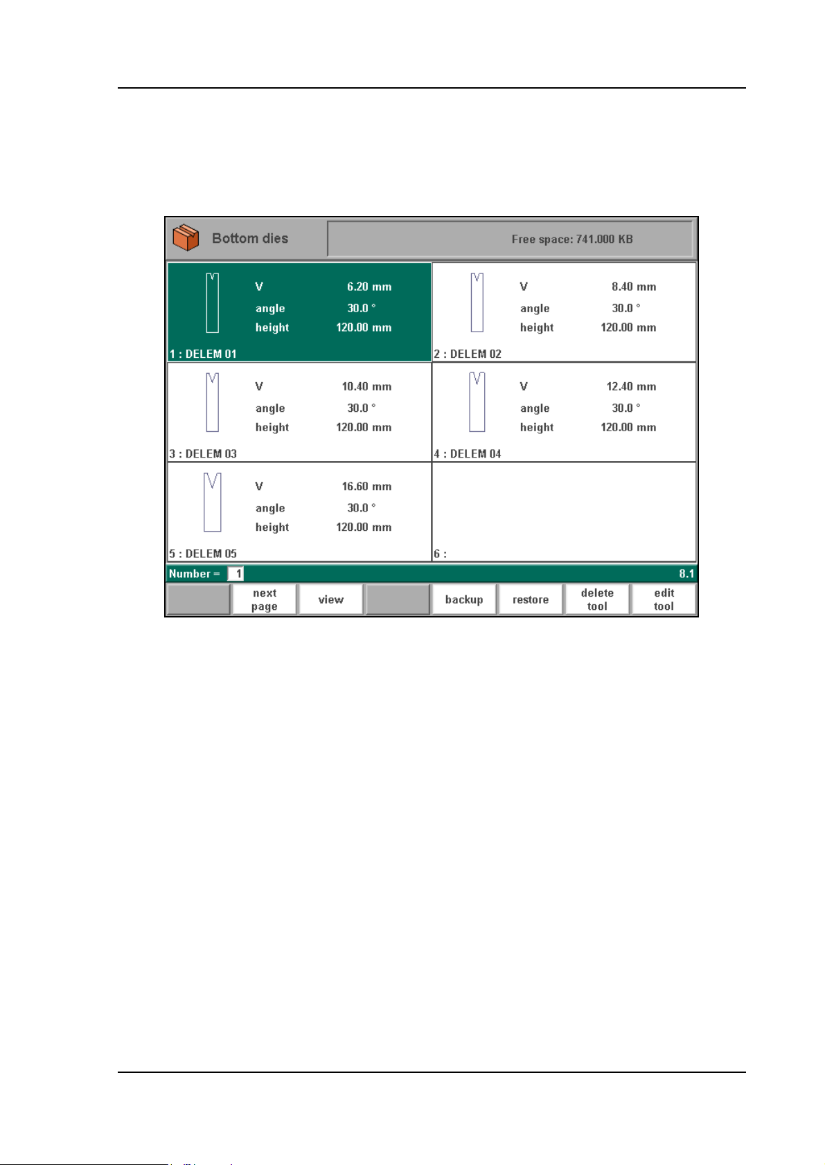
Delem
The other function keys cannot be selected here, until one of these three function keys has been
chosen. The temporary bar will disappear again.
• Graphical directory dies
6.l
• Edit die drawing
When starting the die drawing, the display prompts the main dimensions of the die:
Height. . . . . . . . . . . . . . . . . . . . . . . . . . . . . . . . . . . . . . . . . . . . . . . . . . . .H
The height of the tool. Important: this height value will be used in bend depth calculation.
V-opening. . . . . . . . . . . . . . . . . . . . . . . . . . . . . . . . . . . . . . . . . . . . . . . . .W
The V-opening of the die.
Angle . . . . . . . . . . . . . . . . . . . . . . . . . . . . . . . . . . . . . . . . . . . . . . . . . . . .α
The angle of the die.
Radius . . . . . . . . . . . . . . . . . . . . . . . . . . . . . . . . . . . . . . . . . . . . . . . . . . .RA
The radius of the edges of the V-opening.
V0606, 6.11
Page 90
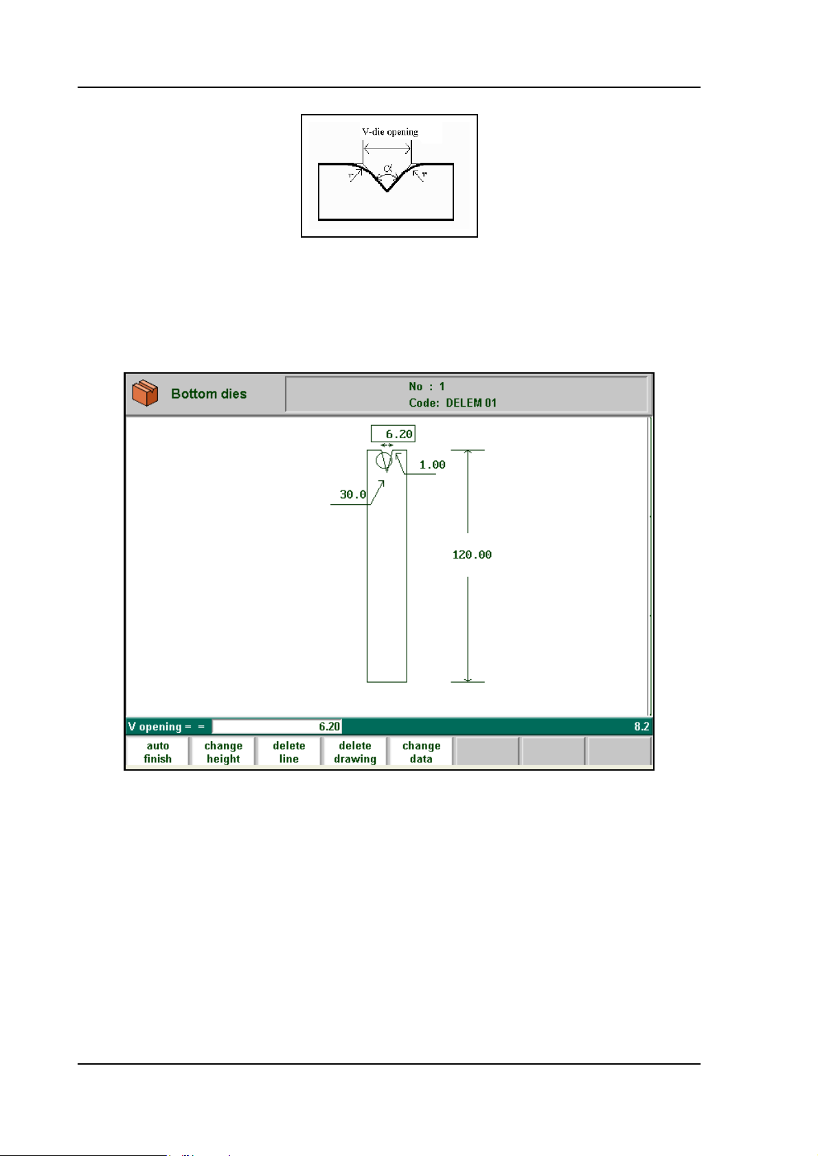
V-die opening:
6.m
The width V is the distance between the touching lines crossing.
After entering these parameters you are ready to draw the important outer dimensions of your
die. The right side of the die is the backgauge position. The mid-position of the V-opening will
be placed on the centre line of the press brake shape.
6.n
The length of the flat section on the right hand side of the V-grove will be used in order to calculate the minimum X-axis position for the R-axis collision detection with die (X-safe).
Function keys:
The softkey functions are exactly the same as for punch programming.
V0606, 6.12
Page 91
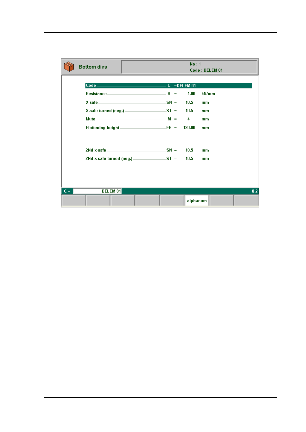
6.3.2. Specific die data
Delem
6.o
Code . . . . . . . . . . . . . . . . . . . . . . . . . . . . . . . . . . . . . . . . . . . . . . . . . . . . .C
Alphanumeric tool name with a maximum 20 characters
Resistance . . . . . . . . . . . . . . . . . . . . . . . . . . . . . . . . . . . . . . . . . . . . . . . .R
Maximum allowable force on the die in kN/mm
X-safe . . . . . . . . . . . . . . . . . . . . . . . . . . . . . . . . . . . . . . . . . . . . . . . . . . . .SN
Calculated safety zone (minimum X-axis value), which will be used in the case a R-axis
is mounted. This to prevent finger to die collision. The indicated minimum value is computed automatically from the die dimensions as follows:
X-SAFE = FS + ½ V in which:
FS = flat section on the right hand side of the V-grove
V = opening value
In this formula also an extra small safety value has been added.
X-safe turned (negative). . . . . . . . . . . . . . . . . . . . . . . . . . . . . . . . . . . . .ST
This second safety value will be active if the die is used in the turned position. This can
be achieved by programming the die in the bendsequence computation with a negative
number. For instance: Program for die number 2: "-2" if you want to use it in the turned
position. In this situation parameter ST will be used as safety zone for the backgauge.
Mute . . . . . . . . . . . . . . . . . . . . . . . . . . . . . . . . . . . . . . . . . . . . . . . . . . . . .M
Muting distance. Distance above the plate at which the speed change takes place.
V0606, 6.13
Page 92
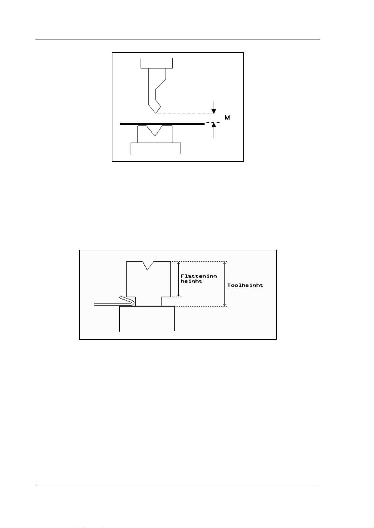
6.p
Flattening height . . . . . . . . . . . . . . . . . . . . . . . . . . . . . . . . . . . . . . . . . .FH
The flattening height need to be programmed when you make use of a special flattening
die to flatten your product.
The programmable height is used to calculate the Y-axis value in case of "flattening".
The default-value for this parameter is the standard tool height, which is already programmed. Every time that this standard height is changed, the flattening height will be
made equal to this tool height (due to safety reasons). See figure 6.r.
6.q
The total height will be used to calculate the speed change point mute and the flattening
height will be used to calculate the end position of the Y-axis beam to flatten the product.
The calculation will take 2x sheet thickness into account. Also you can program a flattening offset in the menu ‘Program constants’. This value will be added to the value of
2x sheet thickness.
2nd x-safe . . . . . . . . . . . . . . . . . . . . . . . . . . . . . . . . . . . . . . . . . . . . . . . .SN=
2nd x-safe turned (negative) . . . . . . . . . . . . . . . . . . . . . . . . . . . . . . . . .ST=
Second automatically calculated safety zone (minimum X-axis value) to be used in the
case a R-axis is mounted. The value is the distance from the middle of the V-opening to
the most outside point of the drawing of the die (on the right side). Also an extra safety
tolerance of 1mm is added. The situation for the die in turned position the distance to the
V0606, 6.14
Page 93

Delem
left side is used. These values are calculated each time the die drawing changes. These
2nd-values cannot be changed manually.
6.r
H2 is the height of the 2nd-values. H2 is not visible on the screen. See for explanation upon the
safety zones the example drawing.
V0606, 6.15
Page 94
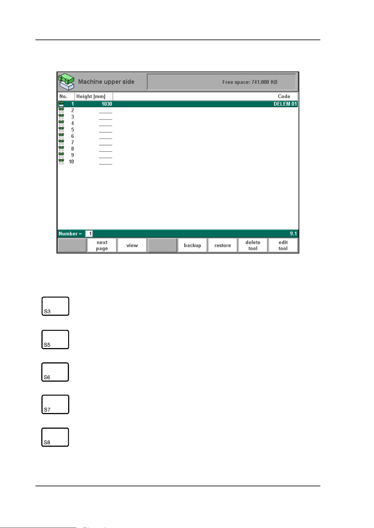
6.4. Machine upper side and lower side
Function keys:
6.s
view Button to select one out of two possible viewing modes:
- dir. expand
- graph. dir.
backup Save tools from library to disk.
restore Load tools from disk into the control.
delete tool Remove tool from library.
edit tool To edit the machine shape drawing or check the dimen-
sions.
When the function key ‘View’ has been pressed a new, temporary button bar appears with
V0606, 6.16
Page 95
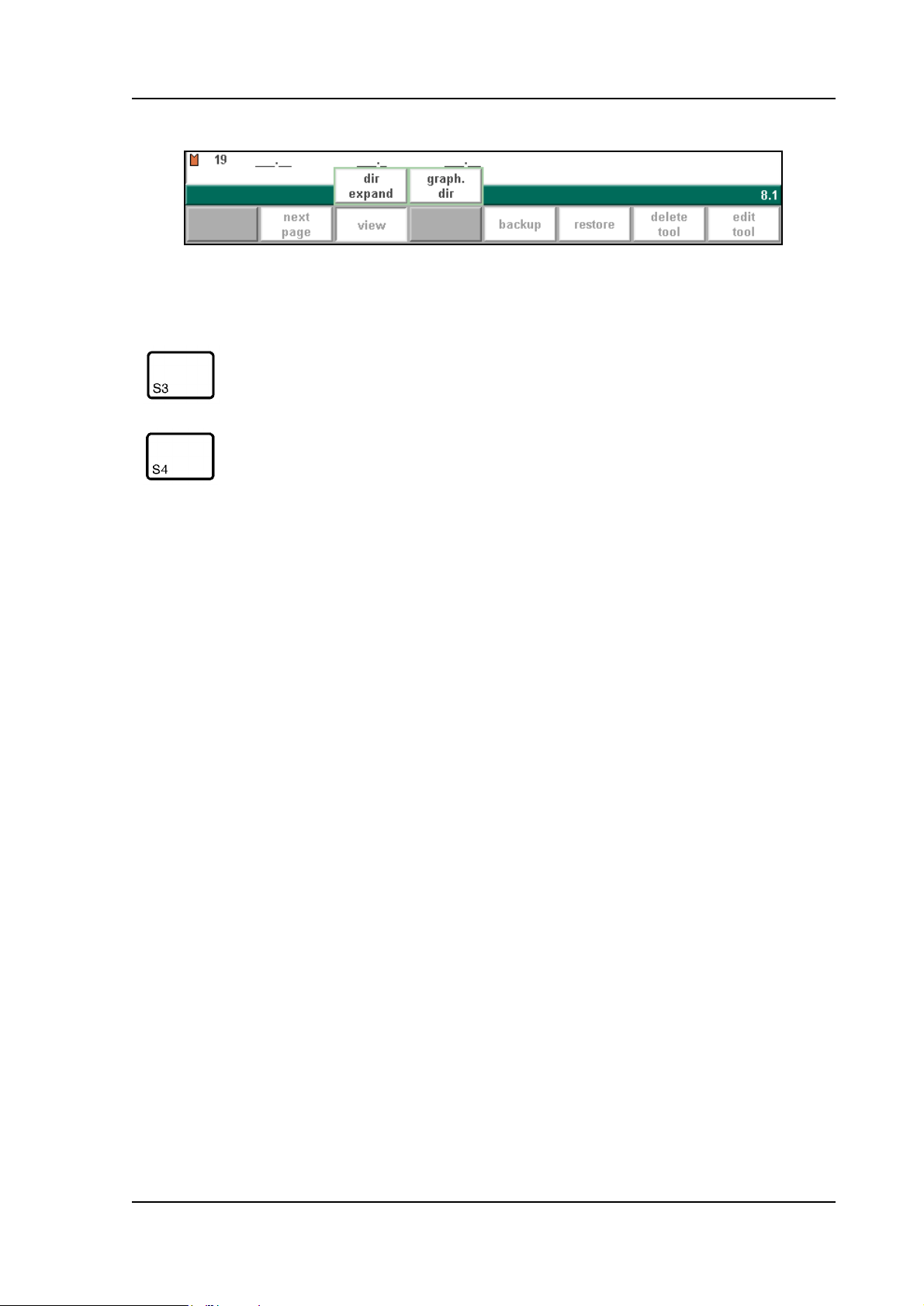
additional softkeys:
Function keys:
dir. expand Select the normal view of the tool collection. This is the
graph. dir To get a graphical overview of the shapes as available in
Delem
6.t
standard setting.
the library including main dimensions.
The other function keys cannot be selected here, until one of these three function keys has been
chosen. The temporary bar will disappear again.
The shapes of your machine are drawn in the same way as for the punches and dies. Like with
the tools the right hand side of the drawing is the backgauge position of the machine.
Before starting drawing the machine shape upper or lower side you must enter the press-beam
height of the upper part when the moving part of the upper side is in its mechanical top dead
centre.
The length prompted after entering the height of the machine shape is the distance from the
center line to the front side or the back side of the machine.
V0606, 6.17
Page 96
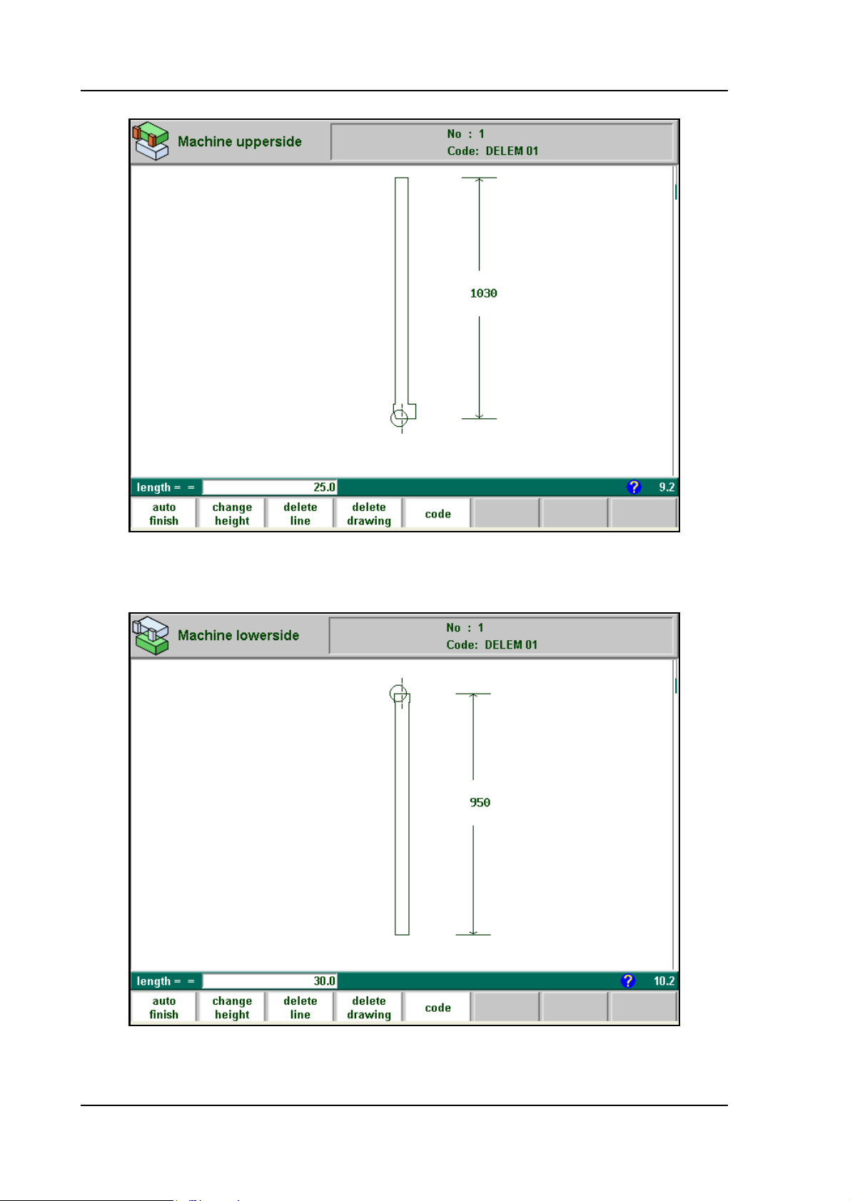
6.u
For the lower side of the machine the height is defined from the table surface to the floor level.
V0606, 6.18
6.v
Page 97
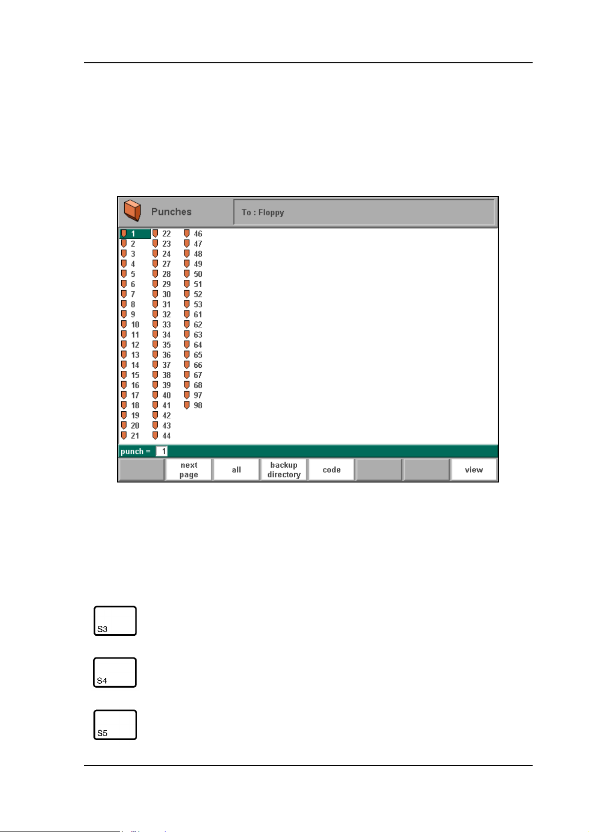
Delem
6.5. Saving/loading of tools
With the function key 'backup' (in any of the tool menus) the dialogue 'Save Punches' is
opened. From this menu, it is possible to save tools to a back-up location. This procedure
works the same for all tools and machine shapes and regardless of the back-up location (floppy
disk, network).
When the function key 'backup' has been pressed, a screen like shown below should appear.
6.w
At the top of the screen, the back-up location is shown. If this location is not correct, you can
change the subdirectory with the softkey 'backup directory'.
To save a tool, enter its number from the list and press 'enter'.
Function keys:
all Save all tools.
backup
directory
code Select on code instead of number.
Change, make or remove a subdirectory where tools will
be saved.
V0606, 6.19
Page 98
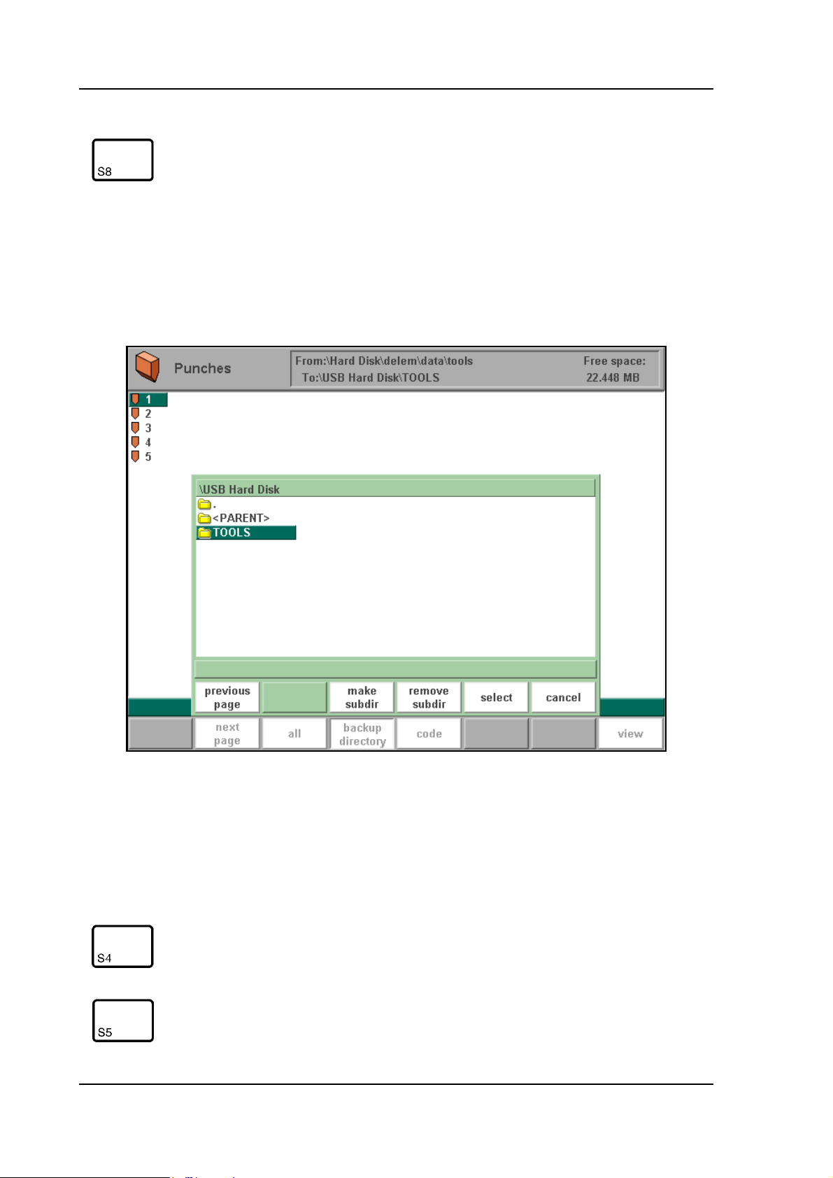
Function keys:
view Button to select one out of two possible viewing modes:
- normal dir.
- dir. expand
- graph. dir.
For backup operations, it is possible to make use of subdirectories. Subdirectories can be created in this menu. When the softkey 'backup directory' is pressed, a new window appears with
a list of available back-up directories. A selected directory can contain products and tools, so
each user can keep his own set of products and tools, if necessary.
6.x
You can make new subdirectories or delete existing ones with the softkeys 'make subdir' and
'remove subdir'. If there are subdirectories present, use the arrow keys to scroll to the required
directory and presss 'enter' to select it.
Function keys:
make subdir
remove
subdir
V0606, 6.20
Add a new subdirectory. The name of the subdirectory
can be any alpha numeric string of maximal 8 characters.
Avoid the use of slashes ('/')
Delete a subdirectory. If the subdirectory is not empty the
controller returns the message 'unable to remove directory'.
Page 99
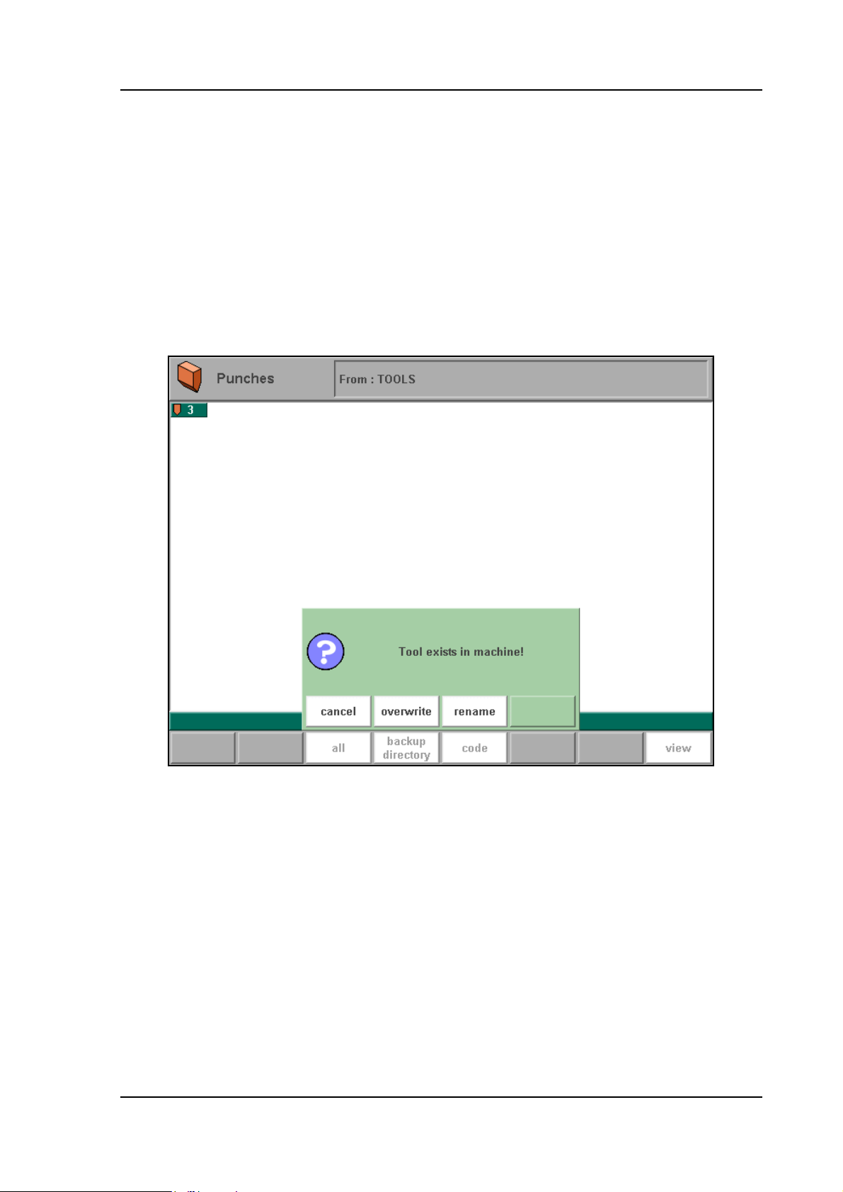
Delem
The 'load tools' procedure is different from the 'save tools' procedure. When you select 'load
tools' the control checks if the toolnumber already exists in the control. If not, then the tool is
automatically copied from disk to the control. If the toolnumber already exists then you have
three options:
-cancel (S3), the toolnumber is not loaded.
-overwrite (S4), the tool in the control is replaced by the tool from disk.
-rename (S5), the tool number of the tool on the disk is first renamed before it is loaded from
disk.
This means (in case of rename) that a new toolnumber is proposed. This new toolnumber is the
first free tool number in the tool library. Accept the proposed tool number with the enter key or
enter the number of another free tool number and press the enter key.
6.y
Note:
Tools are linked to the control by their machine number. When a 'restore' operation is started,
the control will only show those tools, which have the same machine number as the control.
If for any reason the machine number is changed, a new tool back-up operation should be executed to save the control tools with their new machine number.
V0606, 6.21
Page 100

V0606, 6.22
 Loading...