


- 1 -
DA-58
Operation Manual
of version VA.12 GB
Note : |
VA.14 version include VA12 Version plus |
KO Tables permiting |
selection of IT or ST machines.
April 1990
DA580MGB.WP
2
DA-series Press Brake Controllers
Description of Machine Parameters of DA-controllers.
Limited warranty
1.The DA-control has no safety provisions with respect to operator or machine.
Application of the DA-control is totally for the responsibility of the customer. Safety measures must be taken outside the DA-control in order to guarantee a machine operator a safe operation, also in case of any malfunctioning of the DA-control.
Delem can not be held responsible for eventual damages, caused directly or indirectly by the DA-control in normal operation or even when it fails to function according to its specifications.
2.Delem provides the manual "as is" without warranty of any
kind, either expressed or implied; including but not limited to the particular purpose. Delem may make improvements and/or changes in the product(s) and or program(s) described in the manual at any time.
This manual could include the technical inaccuracies or typographical errors. Changes are periodically made in its information. These changes will be incorporated in new editions of the publication.
Requests for copies of this product and for technical information about the products can be made to Delem employees authorised to give this information.
CAUTION:
The product, as described, is equipped with a grounded plug for the safety of the user.
It is to be used in conjunction with a properly grounded receptacle to avoid electrical shock.
- 3 -
DA-58 OPERATION MANUAL
Contents |
|
|
|
|
|
|
|
|
|
paqe |
1. |
OPERATION |
OVERVIEW |
|
|
|
5 |
||||
1.1. |
Operation |
modes |
|
|
|
|
5 |
|||
1.2. |
Front |
panel |
|
|
|
|
|
6 |
||
2. |
PROGRAMMING |
MODE |
|
|
|
8 |
||||
2.1. |
Graphical |
programming |
|
|
|
10 |
||||
2.2. |
Product |
drawing/Product |
edit |
|
|
11 |
||||
2.2.1. |
Control |
keys |
|
|
|
|
14 |
|||
2 . 2 . 2 . |
Delete of an angle/line or insertion of an |
17 |
||||||||
|
angle |
(S1) |
|
|
|
|
|
|
||
2.2.3. |
Precision |
selection (S2) |
|
|
17 |
|||||
2.2.4. |
Big radius |
(Bumping) |
|
|
|
19 |
||||
2.2.5. |
Product data (S3) |
|
|
|
21 |
|||||
2.2.6. |
Assignments |
(S4) |
|
|
|
21 |
||||
|
|
Parameter |
explication |
(page |
1.5/2.5) |
22 |
||||
|
|
Parameter |
explication |
(page |
1.6/2.6) |
23 |
||||
|
|
Parameter |
explication |
(page |
1.7/2.7) |
26 |
||||
|
|
Parameter |
explication |
(page |
1.8/2.8) |
27 |
||||
|
|
Parameter |
explication |
(page |
1.9/2.9) |
28 |
||||
2.2.7. |
Bend |
sequence (S5) |
|
|
|
30 |
||||
|
|
Restoring |
a bend |
sequence |
|
33 |
||||
|
|
Minimum X-axis dimension |
|
33 |
||||||
|
|
Machine/tool selection |
|
|
34 |
|||||
|
|
Turn |
indication |
|
|
|
35 |
|||
|
|
Production time |
|
|
|
35 |
||||
|
|
Screen data |
|
|
|
36 |
||||
|
|
function |
keys |
|
|
|
36 |
|||
|
|
|
|
Bend |
sequence computation (S4) |
37 |
||||
|
|
|
|
Store (S5) |
|
|
|
38 |
||
2.3. |
Data |
preparation/Data edit |
|
|
39 |
|||||
2.3.1. |
Parameters |
explication |
(page |
3.1/4.1) |
41 |
|||||
2.3.2. |
Bending |
programming |
|
|
|
43 |
||||
|
|
Parameter |
explication |
(page |
3.2/4.2) |
44 |
||||
|
|
Parameter |
explication |
(page |
3.3/4.3) |
45 |
||||
|
|
List of bendings of the prepared program |
|
|||||||
|
|
(page |
3.6/4.6) |
|
|
|
48 |
|||
|
|
Ending data preparation/data |
editing |
|
||||||
|
|
(page |
3.5/4.5) |
|
|
|
49 |
|||
|
|
Special edit function |
|
|
50 |
|||||
|
|
Edit |
notes |
|
|
|
50 |
|||
2.4. |
Product |
selection |
|
|
|
51 |
||||
2.5. |
Programmming of |
punches |
|
|
53 |
|||||
2.5.1. |
Specific |
Punch |
Data |
|
|
|
55 |
|||
- 4 -
2.6. |
Programming |
of bottom |
dies |
57 |
|
2.6.1. |
Specific |
die |
data |
|
58 |
2.7. |
Machine |
upperside and |
underside |
60 |
|
2.8. |
Product and Tool Back-up |
61 |
|||
2.8.1. |
Separate |
tool floppy |
|
62 |
|
2.9. |
Program |
constants |
|
63 |
|
2.9.1. |
Serial Interface Specifications |
65 |
|||
3. |
MANUAL MODE |
67 |
3.1. |
Manual operation of the axes |
69 |
3.2. |
Teach in |
70 |
4. |
AUTOMATIC/STEP BY STEP - MODE |
71 |
5. |
EPROM CHANGE |
73 |
5
1. OPERATION OVERVIEW
1.1. Operation modes
The DA-58 has the 4 following modes:
Manual mode
Programming mode
Automatic mode
Step by step mode
Each of these modes is selected with these frontpanel pushbuttons. The selected mode will be indicated with a LED indication in the pushbutton.
Manual mode:
In this mode it is possible to program all parameters of just one bending. After pushing the start button all parameters are active and the X-axis will go into position.
It is also possible to move the axes manually.
Programming mode:
In this mode bend programs can be made or edited and also be written or read to or from the floppy disc, the external memory facility.
Automatic mode:
The selected program can be executed automatically.
Step by step mode:
The selected program can be executed bend by bend.

- 6 -
1.2. Frontpanel
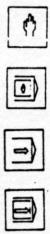
The pushbutton functions besides the 4 operation mode buttons:
0 through 9 |
Numerical keys |
Decimal point
Sign |
|
|
"Teach |
in" key |
|
Help |
key |
|
End |
of |
menu program |
Clear |
, Clearance of the input data field |
|
in the left lower corner on the VDU |
||
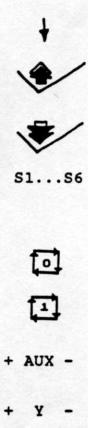
"Enter |
key" |
|
Data |
entering is always closed with enter-key |
|
Cursor "up" movement
7 -
Cursor "down" movement
Previous bend selection
Next bend selection
"Soft keys"
The function of these keys is stated at the bottom side of the VDU
Stop button
Start button
Manual control auxiliary axis
Manual control Y-axis
- 8 -
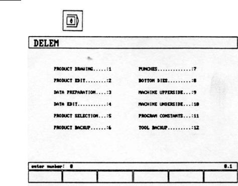
2.PROGRAMMING MODE
With the |
key the programming mode is selected. |
Fig. 2.a
The programming possibilities are selected by entering the menu-number and pushing the enter key.
1 - PRODUCT DRAWING, to draw your product on the VDU-screen and compute the bendsequence
(only with the bendcalculation option)
2 = PRODUCT EDIT, to make correction of your product and compute the bendsequence
(only with the bendcalculation option)
3 = DATA PREPARATION, creation of a new program
4 = DATA EDIT, to edit a program
5 = PRODUCT SELECTION, to select a program out of the memory
6 = PRODUCT BACKUP, write programs to or read programs from the floppy disc. The floppy can be put into the slot on the rearside of the DA-58.
- 9 -
7 = PUNCHES, to program the dimensions of the uppertools
8 = BOTTOM DIES, to program the dimensions of the undertools
9 = MACHINE UPPERSIDE, to program the dimensions of the upperside of your machine.
10= MACHINE UNDERSIDE, to program the dimensions of your machine table
11= PROGRAM CONSTANTS, to program specific programming data
12= TOOL BACKUP, write or read tooling data and machine shapes to or from the floppy disc.

- 10
2.1Graphical programming
From the main menu you can select one of the programming possibilities.
In order to design or edit a new product in Menu selection 1 or 2, the bendcalculation option (OP-BCAL) must be installed.
This option allows fast and simple programming with your DA-58.
The graphical programming option "OP-BCAL" is based upon the "PROFILE" software.
"PROFILE" is a complete product design tool that allows you to draw the profile of your product. "PROFILE" consists of a machine - and tool-library which allows you fast automatic, interactive or manual bending sequence computations with display
of possible product/tool/machine collisions and developed length.
"PROFILE" provides you to select the most optimal bending sequence either to obtain minimum production time or manipulation possibilities of your product.
Features of the "PROFILE" design tool are:
*Graphical design of product shapes
*Auto scaling
*Horizontal and vertical projected dimensions can be entered
*Blank length computation
*Real scale tool design
*100 different machines memory each with 10 different upper side
shapes and 10 different under side shapes (tables)
*Changing of length and angles
*Bumping (big radius)
*Adding or deleting of angles
*Existing products can be copied, changed and be stored as a new product
*Product time indication
* |
Closing dimension or highest precision tolerance selection |
* |
Connecting programs for 3D - production |
"PROFILE" bending sequence computation
* Fast automatic computation for minimum production time
*Interactive bending sequence fixation
*Manual bending sequence fixation
* Collision visualisation of product with tools and machine
*Free tool and machine shape selections
*Assignments of turn times, backgauge speed etc.
*Bending sequence simulation
*Free selection of R-axis position
- 11
Postprocessing of drawings
The postprocess facility computes:
*Fully automatic
*Machine adjustment such as: - Y-axis valve
-Decompression
-X-axis position
-X-axis retract
-Y-opening
-R-axes
-Z-axes
2 . 2 . Product drawing / Product edit
With Menu selection 1 you can draw a new product.
With Menu selection 2 you can make changes in an existing product.
After selecting 1 in the program menu you will have page 1.1 on the VDU/screen. All input data can be found in the enter field in the lower left corner of the screen. On this page you have to enter first the product number and then the drawing number. This last input can be alphanumeric and depending on which letter, you have to press first S4 or S5.
The "±" key prompts a "/" character and the "." key prompts a "-" character in the drawing number.
Fig. 2.2.a

- 12 -
After finishing this input you will get page 1.2 on which you have to enter specific product data. You can start drawing the product on page 1.3.
Selecting the edit mode in the program menu, you will get page 2.3 giving the drawing of the existing product. Via softkey S2 you can go backwards to page 2.2 for changing the product data like in page 1.2.
Fig. 2.2.b
On these pages you can program/change the thickness, kind of material and length in the Z-dimension of your product. Every input must be finished by pressing the enter-key.
Also you must specify whether the dimensions of your drawing
will be inner or outer dimensions. The definition about inner (B) and outer dimensions (A) is given in figure 2.2.c
Fig. 2.2.C Inner/outer dimensions

-
- 13 -
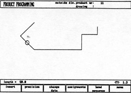
On page 1.3/2.3 you can create/change the product drawing. In the upper information row you will find the information about product number, drawing number and inside/outside dimensions selection.
Fig. 2.2.d |
|
|
For creating the product drawing you have |
to enter the length of |
|
a line and the angle to bend |
in figures or with help of the |
|
drawing cursor for angles of |
multiple 45 |
degrees. |
2.2.1. Control keys
The drawing software uses several function keys on the front panel.
*S1 thru 6
*Drawing cursor control with:
* Horizontal projection definition of entered length
|
with |
the |
key. |
|
* |
Vertical projection |
definition of entered length |
||
|
with |
the |
key. |
|
* |
Zoom |
function: |
|
Enlargement |
|
|
|
|
Reducement |
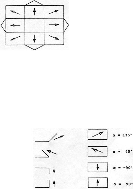
Drawing cursor control
In case you are drawing the profile of your product or
tools the cursor keys can be used to give directly multiples 45 degree angles.
e.g.:
- 15 -
Horizontal or vertical projections
After you entered the length of the line interval you can specify if this line interval is either the nominal length, horizontal
or vertical projection. The given length dimension in the enter field is the line length L if the drawing cursor is in the
concerning |
line. |
|
|
|
|
|
Horizontal |
projection with |
" |
" |
or |
» » |
key. |
Vertical |
projection with |
" |
" |
or " |
" |
key. |
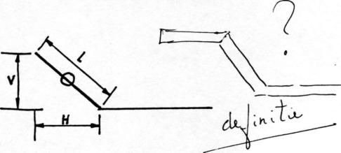
Fig. 2.2.e
L is normal entered line length
V is vertical projected line length
H is horizontal projected line length
It will be noted on the screen if projection is not possible.
Zoomfunction:
The zoomfunction is only active in the simulation drawing.
- 16 -
Function keys:
paragraph
S1 2.2.2
Fig. 2.2.f
Delete of an angle/line or insertion of an angle, depending on the drawing cursor position
822.2.3 Precision: to define selected line segment, with round cursor, for high precision or if it is to be a "closing" dimension.
S3 |
2.2.4 |
Chancre data: |
|
|
To page with product data (page 1.2/2.2) |
S4 |
2.2.5 |
Assignments: |
|
|
To select assignments for bending sequence |
|
|
computations |
S5 |
2.2.6 |
Bend sequence program |
S6 |
|
Return to selection menu |
These functions will be explained in the paragraphs as indicated in the abovementioned overview.

- 17
2.2.2 Delete of an angle/line or insertion of an angle (S1)
The function of this softkey is depending on the position of the drawing cursor.
-If the cursor is within a line segment, it is possible to insert a new angle to bend.
-If the cursor is positioned on an angle, it is possible to delete that angle.
-If the cursor is at an end line of the product, the line can be deleted.
2.2.3Precision selection (S2)
When the drawing cursor (small circle) is in a line segment, with S2 high precision or closing dimension can be selected.
With S2 these functions will be toggled giving 3 possibilities (high precision - closing dimension - normal situation)
-High precision (marked green) :
At bend sequence computation the backgauge stop position will be chosen to get the highest possible precision of this line interval.
-Closing dimension (marked red) :
At bend sequence computation the backgauge stop position will be chosen to get the resulting tolerances in this line interval.
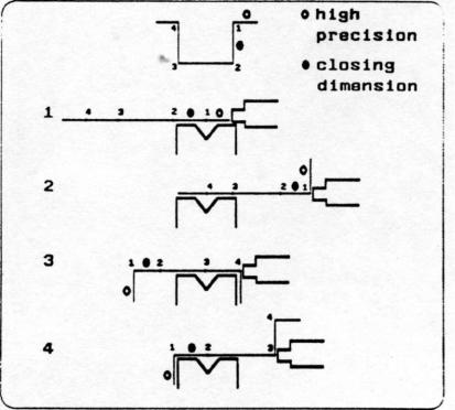
18 -
Example:
Line interval marked with the open circle is never between back stop and the centre of the die.
Notes:
Specifying line intervals with high precision and closing dimensions may result in longer production time.
Also it will have priority over the "front extend ratio", if that is selected to "comply if possible".
- 19 -
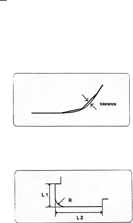
2.2.4Big Radius (Bumping)
When the cursor is on an angle you can select a big radius by pressing function key S2. After pressing S2 you are prompted to program the following parameters.
radius |
= the desired radius in mm |
|
tolerance |
= the allowed tolerance in |
mm |
A smaller tolerance will result in more bendings necessary to realize the radius. The V-die opening which must be used to realize the big radius is decreasing when a smaller tolerance is specified. For the tolerance definition see figure 2.2.4.a.
Fig. 2.2.4.a
For the definition of the line lengths to be programmed in the part connected to a bump radius segment, see figure 2.2.4.b.
Fig. 2.2.4.b
Lengths L1 and L2 must be equal or bigger than the radius R. After programming these parameters the radius is drawn in the product and the maximal V-die opening which can be used is displayed on the screen.
When the cursor is on a radius and S2 is pressed again the radius will be deleted and changed back to a single angle (toggle function). For the screen information see figure 2.2.4.C

- 20 -
Fig. 2.2.4.C
- 21 -
2.2.5 Product data (S3)
Pressing S3 results in the product data overview of page 1.2/2.2. On that page you can return to the drawing again via softkey S6.
2.2.6 Assignments (S4)
Pressing S4 on page 1.3/2.3 results in the parameter pages starting on page 1.5/2.5.
Automatic bend sequence computation works with several criteria in order to find an optimum between a minimum
production time, handling possibilities without product/machine and product/tool collision.
In order to find one of the optimums you must program several computation parameters with which the bend sequence can be computed.
Some of these parameters are machine related, axis speeds a.o. and some are related to handling possibilities and turn times.
Page 1.5/2.5 gives the first page of these assignments.
Fig. 2.2.6.a
parameter explication (paqe 1.5/2.5)
OPTIMALISATION DEGREE OD=
Range 1-5
The number of alternative sequences to be computed for each bending must be entered here.
The higher this number the more alternatives are to be examined by the processor, so the longer the computing time will take.
X-AXIS SPEED |
BS= |
|
|
|
|
Speed of the backgauge of your press brake
R-AXIS SPEED |
RS= |
|
|
|
|
Speed of the R-axis fingers
FRONT EXTEND RATIO .... |
FR= |
This is the ratio of the minimum allowable length of your product which extends in front of the press to the total blank length of the product. You must have a minimum length
of your product in front of the press to be able to handle the product. Max. possible value = .49
FRONT EXTEND RATIO ACCEPT ....FA*
- In case programmed 0 (comply if possible) :
This means that when possible the computer tries to comply to the front extend ratio and only when this will result in no solutions to be found it will accept that the length in front is smaller than the specified ratio.
- In case programmed 1 (comply always) :
The computer will always comply to the front extend ratio. This may result in no solutions to be found.
Softkey functions;
S1 = previous page S 2 - next page
S6 - draw, to go back to the drawing on page 1.3/2.3
 Loading...