


TWH 200E

Export
C003182-B
KALIKO
Thermodynamic water heater
TWH 200E
TWH 300E
TWH 300EH
EN
Installation and
Service Manual
300026515-001-03

Declaration of conformity
The device complies with the standard type described in the EG
declaration of conformity. It was manufactured and commissioned in
accordance with European directives.
The original declaration of conformity is available from the
manufacturer.

Contents
1 Introduction ................................................................................................6
1.1 Symbols used .......................................................6
1.2 Abbreviations ........................................................6
1.3 General ..................................................................7
1.3.1 Manufacturer’s liability .............................................7
1.3.2 Installer’s liability .....................................................7
1.4 Homologations ......................................................7
1.4.1 Certifications ...........................................................7
1.4.2 Directive 97/23/EC ..................................................8
1.4.3 Factory test .............................................................8
2 Safety instructions and recommendations ..............................................9
2.1 Safety instructions ...............................................9
2.2 Recommendations ................................................9
2.3 Safety data sheet: R-134a refrigerant ...............10
2.3.1 Product identification .............................................10
2.3.2 Hazard identification ..............................................10
2.3.3 Composition / Information on the ingredients ........10
2.3.4 First aid .................................................................10
2.3.5 Fire prevention measures .....................................10
2.3.6 In the event of accidental spillage .........................11
2.3.7 Handling ................................................................11
2.3.8 Personal protection ...............................................11
2.3.9 Considerations on disposal ...................................12
2.3.10 Regulations ...........................................................12
3 Technical description ..............................................................................13
3.1 General description ............................................13
3.2 Main parts ............................................................14
3.3 Operating principle .............................................14
3.4 Technical specifications ....................................15
03/02/2014 - 300026515-001-03
3.4.1 Characteristics of the appliance ............................15
3.4.2 Heating time of the DHW tank depending on the air
temperature ...........................................................16
3.4.3 Max domestic hot water set point reached by the heat
pump depending on the air temperature ...............16
1

Contents
4 Installation ................................................................................................17
4.1 Regulations governing installation ...................17
4.2 Package list .........................................................17
4.2.1 Standard delivery ..................................................17
4.2.2 Accessories ...........................................................17
4.3 Storage and transport ........................................18
4.3.1 Transport ...............................................................18
4.4 Choice of the location ........................................19
4.4.1 Type plate .............................................................19
4.4.2 Positioning of the appliance ..................................19
4.4.3 Main dimensions ...................................................23
4.5 Positioning the appliance ..................................25
4.5.1 Unpacking the appliance .......................................25
4.5.2 Positioning the appliance ......................................25
4.5.3 Levelling ................................................................26
4.6 Hydraulic connections .......................................26
4.6.1 Connecting the calorifer to the domestic water circuit
(secondary circuit) .................................................26
4.6.2 Connection to a boiler (Version EH) ......................28
4.6.3 Connection to solar collectors (Version EH) .........30
4.7 Condensates discharge .....................................32
4.8 Installing the control system in the living
room .....................................................................32
4.8.1 Choose a location .................................................32
4.8.2 Operations to be carried out on the thermodynamic
DHW tank ..............................................................33
4.8.3 Installing the control system in the living
room ......................................................................34
4.9 Electrical connections ........................................35
4.9.1 Recommendations ................................................35
4.9.2 Connecting the hydraulic back-up (Version
EH) ........................................................................35
4.9.3 Access to the connection terminal HP/HC ............36
4.9.4 Connection with HP/HC signal connected ............37
4.9.5 Connection with timer programming .....................39
4.9.6 Connection with timer programming and photovoltaic
signal .....................................................................40
4.10 Electrical principle diagram ...............................41
4.11 Filling the thermodynamic DHW tank ...............42
5 Commissioning ........................................................................................43
5.1 Control panel .......................................................43
5.1.1 Description of the keys ..........................................43
5.1.2 Description of the display ......................................43
03/02/2014 - 300026515-001-03
2

5.1.3 Browsing in the menus ..........................................45
5.2 Check points before commissioning ................45
5.3 Putting the appliance into operation ................46
5.3.1 Commissioning ......................................................46
5.4 Checks and adjustments after
commissioning ...................................................46
5.5 Choosing the operating mode ...........................46
5.6 Reading out measured values ...........................47
5.6.1 Measurements menu ............................................47
5.6.2 Counters ................................................................47
5.7 Modifying the installer parameters ...................49
5.7.1 Access to parameters ...........................................49
5.7.2 List of the parameters ...........................................50
5.7.3 Control system sequence ......................................51
5.7.4 Return to the factory settings ................................51
6 Switching off the appliance .....................................................................53
6.1 Installation shutdown .........................................53
6.2 Antifreeze protection ..........................................53
7 Checking and maintenance .....................................................................54
7.1 General instructions ...........................................54
7.2 Maintenance operations to be performed ........55
7.2.1 Refrigerant circuit ..................................................55
7.2.2 Hydraulic circuit .....................................................55
7.2.3 Aeraulics ...............................................................55
7.2.4 Impressed current anode ......................................55
7.2.5 Checking the safety valve or unit ..........................55
7.2.6 Descaling ..............................................................56
7.2.7 Cleaning the condensates discharge duct ............56
7.3 Accessing the bottom inspection trap .............57
7.4 Maintenance form ...............................................58
8 Troubleshooting .......................................................................................59
03/02/2014 - 300026515-001-03
8.1 Messages (Code type bxx or Exx) .....................59
8.1.1 Messages (type code bXX) ..............................59
8.1.2 Messages (type code EXX) ..............................61
8.2 Message and error history .................................62
8.2.1 Err error display ....................................................63
8.2.2 bL blockage display ...............................................63
8.2.3 Reset error and blockage history ..........................63
3

Contents
9 Spare parts ................................................................................................64
9.1 General ................................................................64
9.2 Spare parts ..........................................................64
9.2.1 Heat pump .............................................................64
9.2.2 DHW tank ..............................................................66
03/02/2014 - 300026515-001-03
4

03/02/2014 - 300026515-001-03
5
1. Introduction
1 Introduction
1.1 Symbols used
TWH 200E TWH 300E TWH 300EH
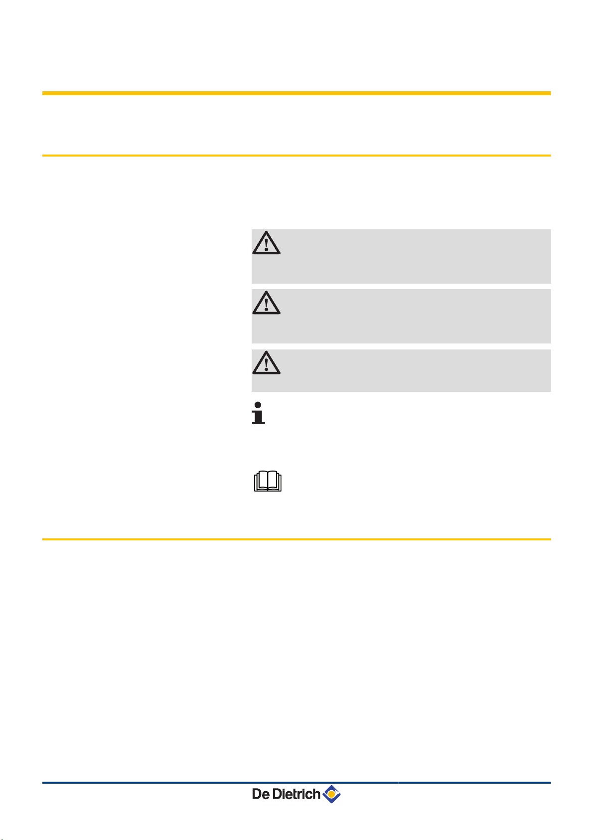
In these instructions, various danger levels are employed to draw the
user’s attention to particular information. In so doing, we wish to
safeguard the user’s safety, obviate hazards and guarantee correct
operation of the appliance.
DANGER
Risk of a dangerous situation causing serious physical
injury.
WARNING
Risk of a dangerous situation causing slight physical
injury.
1.2 Abbreviations
CAUTION
Risk of material damage.
Signals important information.
¼Signals a referral to other instructions or other pages in the
instructions.
Before installing and commissioning the device, read
carefully the instruction manuals provided.
4 HP: Heat pump
4 DHW: Domestic hot water
4 LP: Low pressure
4 HP: High pressure
4 CFC: Chlorofluorocarbon
4 Qpr: Static losses (Thermal losses from the DHW tank when it is
off for 24 hours)
4 COP: Performance coefficient
4 HP/HC: Peak hours / Off-peak hours
6
03/02/2014 - 300026515-001-03

TWH 200E TWH 300E TWH 300EH
1.3 General
1. Introduction
1.3.1. Manufacturer’s liability
Our products are manufactured in compliance with the requirements
of the various applicable European Directives. They are therefore
delivered with [ marking and all relevant documentation.
In the interest of customers, we are continuously endeavouring to
make improvements in product quality. All the specifications stated in
this document are therefore subject to change without notice.
Our liability as the manufacturer may not be invoked in the following
cases:
4 Failure to abide by the instructions on using the appliance.
4 Faulty or insufficient maintenance of the appliance.
4 Failure to abide by the instructions on installing the appliance.
1.4 Homologations
1.3.2. Installer’s liability
The installer is responsible for the installation and inital start up of the
appliance. The installer must respect the following instructions:
4 Read and follow the instructions given in the manuals provided
with the appliance.
4 Carry out installation in compliance with the prevailing legislation
and standards.
4 Perform the initial start up and carry out any checks necessary.
4 Explain the installation to the user.
4 If a maintenance is necessary, warn the user of the obligation to
check the appliance and maintain it in good working order.
4 Give all the instruction manuals to the user.
1.4.1. Certifications
03/02/2014 - 300026515-001-03
Electrical compliance / Marking CE
n
This product complies to the requirements to the european directives
and following standards:
4 2006/95/EC Low Voltage Directive
Reference Standard: EN 60.335.1.
4 2004/108/EC Electromagnetic Compatibility Directive
7

1. Introduction TWH 200E TWH 300E TWH 300EH
Reference Standard: EN 50.081.1 / EN 50.082.1 / EN 55.014.
1.4.2. Directive 97/23/EC
This product conforms to the requirements of european directive 97 /
23 / EC, article 3, paragraph 3, on pressure equipment.
1.4.3. Factory test
Before leaving the factory, each appliance is tested for the following:
4 Water tightness
4 Air tightness
4 Electrical safety.
8
03/02/2014 - 300026515-001-03

TWH 200E TWH 300E TWH 300EH 2. Safety instructions and recommendations
2 Safety instructions and
recommendations
2.1 Safety instructions
DANGER
If smoke is released or in case of refrigerant leak:
1. Do not use a naked flame, do not smoke, do not
operate electrical contacts or switches ( doorbell,
light, motor, lift, etc..).
2. Open the windows.
3. Switch the appliance off.
4. Avoid contact with the refrigerant. Danger of frost
injuries.
5. Trace possible leaks and seal them immediately.
2.2 Recommendations
WARNING
Depending on the settings of the appliance:
4 Do not touch the refrigeration connection pipes with
your bare hands while the appliance is running. Risk
of being burnt.
CAUTION
4 Do not neglect to service the appliance.
4 In order to limit the risk of being scalded, the
installation of a thermostatic mixing valve on the
domestic hot water flow piping is compulsory.
WARNING
Only certified professionals having received adequate
training are permitted to work on the appliance and the
installation.
03/02/2014 - 300026515-001-03
WARNING
Before any work, switch off the mains supply to the
appliance.
9
2. Safety instructions and recommendations
2.3 Safety data sheet: R-134a refrigerant
2.3.1. Product identification
4 Refrigerant name: R-134a
2.3.2. Hazard identification
4 Effects harmful to health:
- The vapours are heavier than air and may lead to asphyxia
owing to reduced oxygen levels.
- Liquefied gas: Contact with the liquid may cause serious frost
and eye injuries.
4 Product classification: This product is not classified as a
"hazardous preparation" according to European Union
regulations.
TWH 200E TWH 300E TWH 300EH
2.3.3. Composition / Information on the
ingredients
4 Chemical nature: 1,1,1,2-Tetrafluoroethane R-134a.
4 Ingredients that may lead to hazardous situations:
Substance name
1,1,1,2-Tetrafluoroethane R-134a 100 % 811-97-2 212-377-0
Concentration CAS number CE number Classification GWP
2.3.4. First aid
4 If inhaled: Evacuate the subject from the contaminated area and
take him into the open air.
If feeling unwell: Call a doctor.
4 In the event of contact with the skin: Treat frost injuries as
burns. Rinse in abundant water, do not remove clothing (risk of
adhesion to the skin).
If skin burns appear, call a doctor immediately.
4 In the event of contact with the eyes: Rinse immediately in
water, holding the eyelids well apart (at least 15 minutes).
Consult an ophthalmologist immediately.
1300
10
2.3.5. Fire prevention measures
4 Appropriate extinguishing agents: All extinguishing agents can be
used.
03/02/2014 - 300026515-001-03

TWH 200E TWH 300E TWH 300EH
2. Safety instructions and recommendations
4 Inappropriate extinguishing agents: None to our knowledge. In the
event of fire nearby, use the appropriate extinguishing agents.
4 Specific hazards:
- Rise in pressure.
In the presence of air, an inflammable mixture may form under
certain temperature and pressure conditions
- Toxic and corrosive vapours may be released by the effect of
the heat.
4 Special intervention methods: Cool the volumes exposed to heat
with water spray.
4 Protection of the firemen:
- Full facepiece self-contained breathing apparatus
- Complete body protection.
2.3.6. In the event of accidental spillage
4 Individual precautions:
- Avoid contact with the skin and eyes
- Do not intervene without appropriate protective equipment
- Do not inhale the vapours
- Evacuate the hazardous area
- Stop the leakage
- Eradicate all sources of ignition
- Ventilate the spillage area mechanically (Risk of asphyxia).
4 Cleaning / Decontamination: Allow residual product to evaporate.
2.3.7. Handling
4 Technical measures: Ventilation.
4 Precautions to be taken:
- No smoking
- Prevent the accumulation of electrostatic charges
- Work in a well ventilated place.
2.3.8. Personal protection
4 Respiratory protection:
- If insufficient ventilation: AX type cartridge mask
- In confined spaces: Full facepiece self-contained breathing
apparatus.
4 Hand protection: Protective gloves in leather or nitrile rubber.
4 Eye protection: Safety glasses with side protection.
4 Skin protection: Clothing made mostly of cotton.
4 Industrial hygiene: Do not drink, eat or smoke at the place of work.
03/02/2014 - 300026515-001-03
11

2. Safety instructions and recommendations TWH 200E TWH 300E TWH 300EH
2.3.9. Considerations on disposal
4 Product waste: Consult the manufacturer or the supplier for
information on recovery or recycling.
4 Soiled packaging: Reuse or recycle after decontamination.
Destroy in authorised installations.
WARNING
Disposal must be done in compliance with prevailing local
and national regulations.
2.3.10. Regulations
4 EC Regulation 842/2006: Fluorinated greenhouse gases under
the Kyoto Protocol.
12
03/02/2014 - 300026515-001-03

TWH 200E TWH 300E TWH 300EH 3. Technical description
3 Technical description
3.1 General description
The DHW tanks in the TWH range have the following characteristics:
4 Floor-standing thermodynamic storage DHW tank
4 Thermodynamic unit extracting energy from unheated ambient air
or outside air
4 Control panel with display of the volume of water heated and
hourly programming
4 Heat exchanger for connection to a boiler or a solar circuit (Version
EH)
4 Steatite electrical resistor 2.4 kW
4 Enamelled tank protected by impressed current anode
4 Very thick insulation (0% CFCs)
The thermodynamic water heater is a hot water tank that can be
heated by:
4 The Heat Pump (up to 65°C)
4 The electric heating resistance (Electrical back-up - AUTO and
Boost mode) (up to 70°C)
4 The additional heat exchanger (Version EH)
03/02/2014 - 300026515-001-03
13
C003185-F
5
6
10
2
1
3
4
15
16
13
12
14
17
11
19
18
8
7
9
3. Technical description
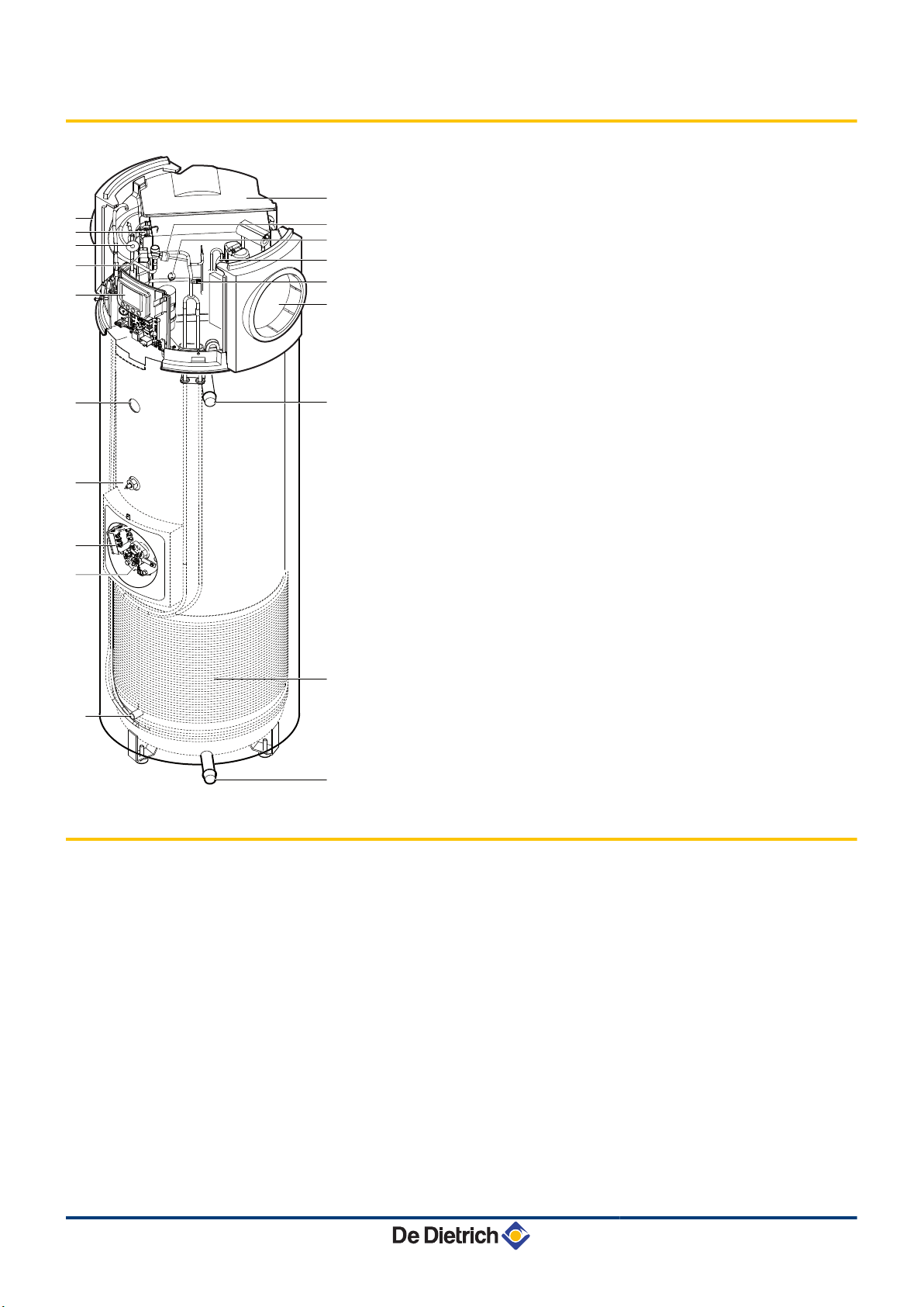
3.2 Main parts
TWH 200E TWH 300E TWH 300EH
1
2
3
4
5
6
7
8
9
10
11
12
13
14
15
16
17
Fan
Evaporator
Expansion valve
Solenoid valve for defrosting
Regulation
temperature sensor
Impressed current anode
Safety thermostat
Steatite electrical resistor
temperature sensor
Air conduits
High pressure (HP) pressure switch
Low pressure (LP) pressure switch
Compressor
Pressure measurement point - High pressure (HP)
Ventilation grid
Domestic hot water outlet
18
19
Condenser
Cold water inlet
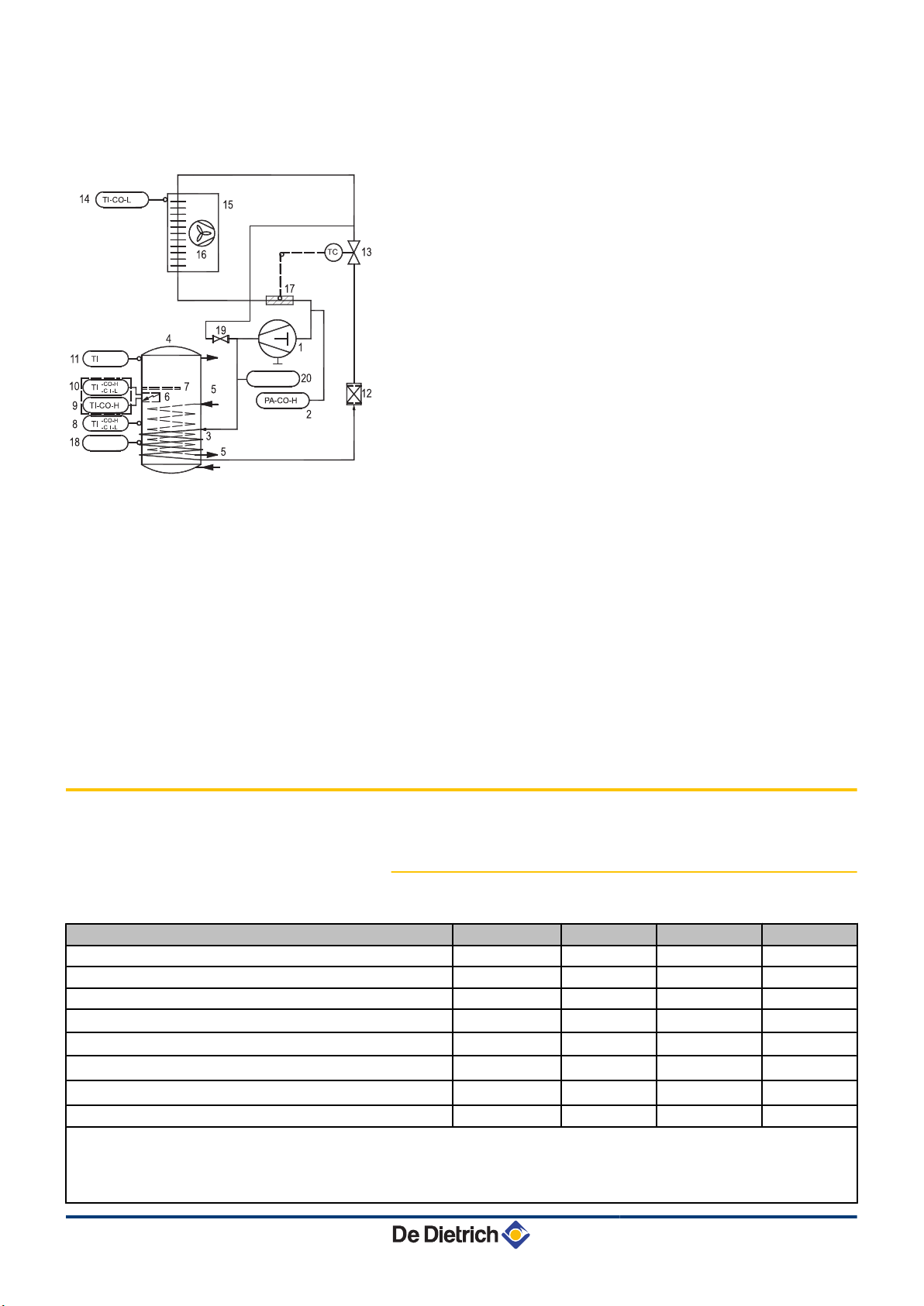
3.3 Operating principle
The thermodynamic DHW tank uses unheated ambient air or outside
air to prepare DHW.
The refrigerant circuit is a closed circuit in which the R-134a
refrigerant plays the role of an energy carrier.
The heat from the intake air is transferred to the refrigerant in the
finned heat exchanger at a low evaporation temperature.
The refrigerant is sucked in by a compressor in vapour form, which
raises it to a higher pressure and temperature and sends it to the
condenser. In the condenser, the heat extracted in the evaporator and
some of the energy absorbed by the compressor are released into
the water.
14
03/02/2014 - 300026515-001-03
C003625-D
TWH 200E TWH 300E TWH 300EH 3. Technical description
The refrigerant is depressurised in the thermostatic expansion valve
and is cooled. The refrigerant can again extract the heat contained in
the inlet air into the evaporator.
1
2
3
4
5
6
7
8
9
10
11
12
13
14
15
16
Compressor
Low pressure (LP) pressure switch
Condenser
Domestic hot water tank
Heat exchanger (Version EH)
Steatite electrical resistor
Impressed current anode
Temperature regulator (HP)
Limiting thermostat
Temperature regulator (Electric heating
resistance)
Sensor tube
Filter-drier
Thermostatic expansion valve
Ambient air thermostat
Evaporator
Fan
17
18
19
20
Expansion valve bulb
Sensor tube
Solenoid valve for defrosting
High pressure (HP) pressure switch
3.4 Technical specifications
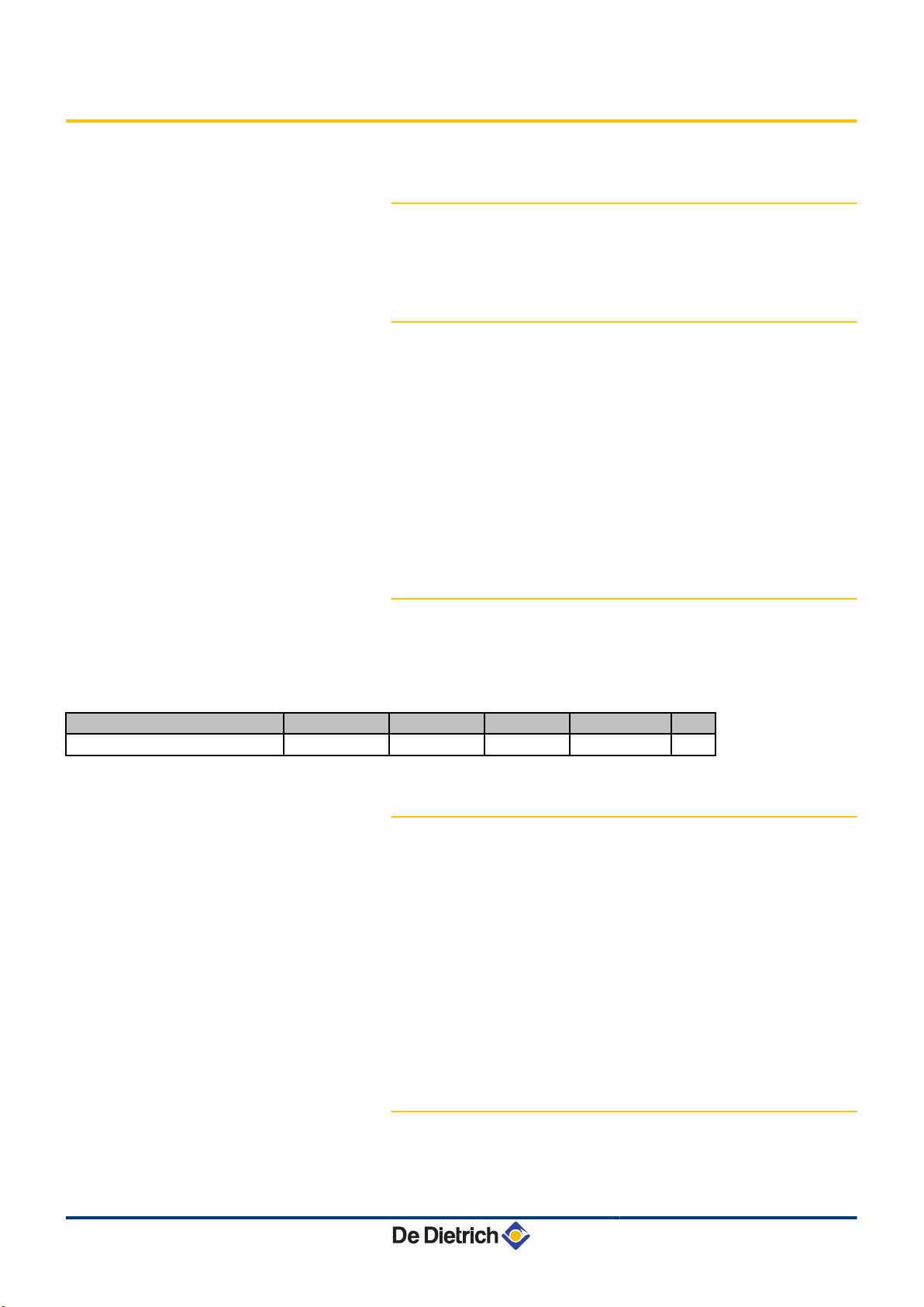
3.4.1. Characteristics of the appliance
Model
Capacity litres 270 265 215
Output (HP) -Air temperature = 15°C W 1700 1700 1700
Absorbed electrical power (HP) W 500 500 500
(1)
COP
(2)
COP
Air flow rate - maximum
Nominal air flow rate (DP = 25 Pa)
Electrical resistor output W 2400 2400 2400
(1) Value obtained at an air temperature of 15°C and a relative humidity of 70%. Water inlet temperature at 15°C in accordance with EN255-3.
(2) Value obtained with an air temperature of 7 and a water inlet at 10 °C, as per EN16147 based on Specification LCIE N°103-15/B:2011
(3) Domestic cold water input at 10°C - Primary inlet temperature at 80°C
(4) Output: 34.1 kW
(5) The installation of suction and backflow conduits on the heat pump lessens its performance
(2)
m3/h
m3/h
TWH 300 E TWH 300 EH TWH 200 E
3.7 3.6 3.5
2.94 2.75 2.90
385 385 385
320 320 320
03/02/2014 - 300026515-001-03
15

0
2
4
6
8
10
12
14
16
18
20
-5 0 5 10 15 20 25 30 35
Y
X
B
A
C003447-A
C003483-B
51°
-5 0 5 7 10 X
55°
65°
Y
3. Technical description TWH 200E TWH 300E TWH 300EH
Model
TWH 300 E TWH 300 EH TWH 200 E
Operating pressure bar (MPa) 10 10 10
Power supply voltage V 230 230 230
Circuit breaker A 16 16 16
Exchanger surface
Continuous output DT = 35 K
Flow rate over 10 minutes with DT = 30 K
Heating time (15-51 °C)
(1)
Qpr
(1)
V40
(2)
Vmax
(2)
Pes
(3) (4)
(3)
(1)
Maximum length of the air connection Diameter 160 mm
(5)
2
m
- 1.00 -
litres per hour - 955.6 -
l/10 mm - 420 -
Hours 7 7 5
kWh/24h 0.67 0.75 0.73
litres 357 358 240
litres 388 383 281.9
W 34 36 30
m 25 25 25
R134a refrigerant kg 1.45 1.45 1.45
Weight (empty) kg 105 123 92
(1) Value obtained at an air temperature of 15°C and a relative humidity of 70%. Water inlet temperature at 15°C in accordance with EN255-3.
(2) Value obtained with an air temperature of 7 and a water inlet at 10 °C, as per EN16147 based on Specification LCIE N°103-15/B:2011
(3) Domestic cold water input at 10°C - Primary inlet temperature at 80°C
(4) Output: 34.1 kW
(5) The installation of suction and backflow conduits on the heat pump lessens its performance
3.4.2. Heating time of the DHW tank depending on
the air temperature
Scenario for complete heating of the DHW tank
A
B
Y
X
Heating time for a set point of 51°C
Heating time for a set point of 62°C
Heating time (Hours)
Air temperature (°C)
3.4.3. Max domestic hot water set point reached
by the heat pump depending on the air
temperature
Y
Max domestic hot water temperature (°C)
16
X
Air temperature (°C)
03/02/2014 - 300026515-001-03
TWH 200E TWH 300E TWH 300EH 4. Installation
4 Installation
4.1 Regulations governing installation
CAUTION
Installation and maintenance of the appliance must be
done by a qualified professional in accordance with
prevailing statutory texts and codes of practice.
4.2 Package list
4.2.1. Standard delivery
The delivery includes:
4 The thermodynamic DHW tank x1
4 Dielectric connection (delivered in the instructions bag for the
DHW tank) (2x)
4 Lip gasket (2x)
4 Condensate evacuation hose (1x)
4 Instructions + Kyoto Protocol sticker (1x)
4 Hose holding clip (1x)
4 The user instructions
4 The installation and maintenance instructions
4.2.2. Accessories
Accessories
Galvanised 90° elbow (Diameter 160 mm) EH 77
Adapter sleeve (Diameter 160 mm) EH 205
Insulated flexible duct (Diameter 160 mm - Length 3 m) EH 206
Set of 2 retaining clamps (Diameter 160 mm) EH 207
Passing through walls (Diameter 160 mm) + Closing plate EH 208
Outside grid (Diameter 160 mm) (aluminium) EH 209
PPE duct (Diameter 160 mm - Length 2x1 m) + 2 sleeves EH 272
290° elbows (PPE) (Diameter 160 mm) + 2 sleeves EH 273
2 sleeves PPE (Diameter 160 mm) EH 274
Roof outlet Black (Diameter 160 mm) EH 275
Tightness bed plate for flat roof (Diameter 160 mm) EH 276
package
03/02/2014 - 300026515-001-03
17
C003496-B
4. Installation TWH 200E TWH 300E TWH 300EH
Accessories package
Tightness bed plate for sloping roof 25 to 45° (Diameter 160
mm)
Reduced elbow kit EH 434
Connection kit for safety unit ER 208
EH 277
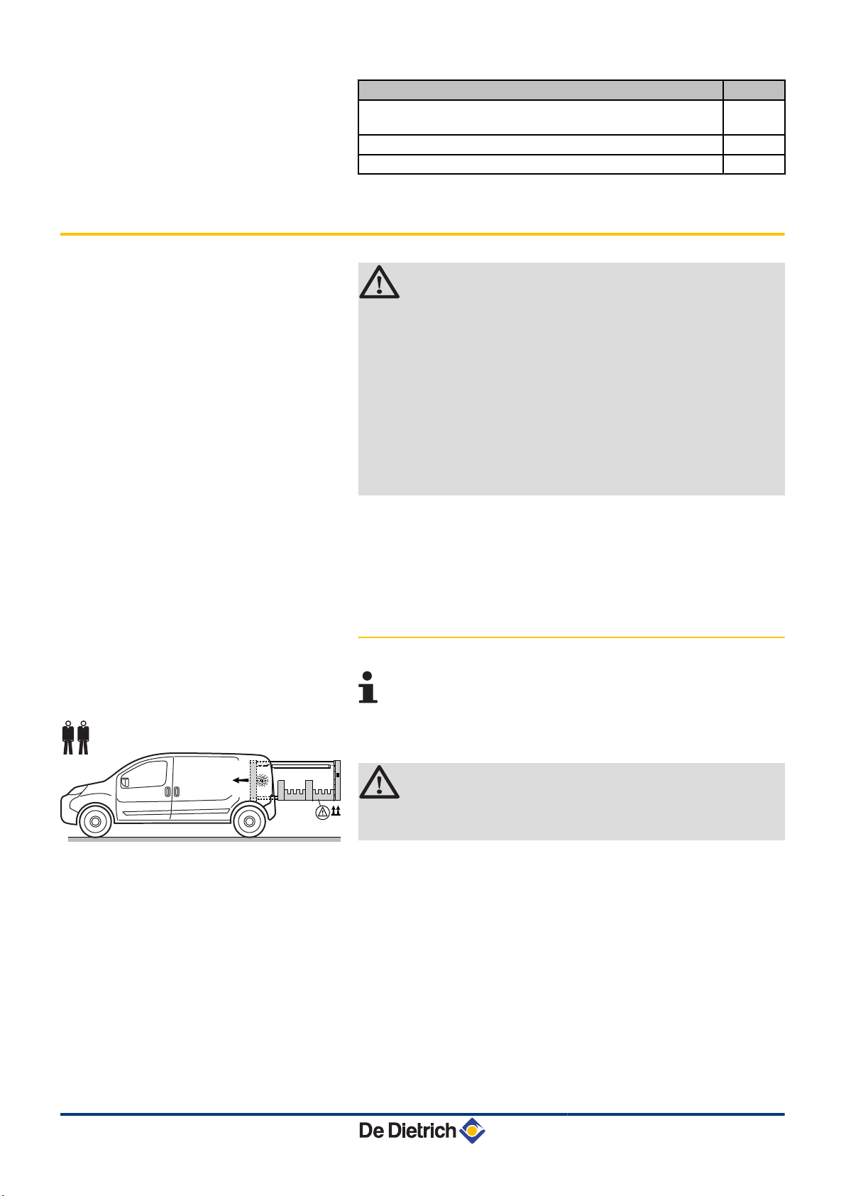
4.3 Storage and transport
CAUTION
4 Have 2 people available.
4 Use a 3-wheel hand truck.
4 Handle the appliance with gloves.
4 The appliance cover cannot be used for transport
operations. The cover is not capable of withstanding
heavy weights.
4 Model 300 : Allow a minimum room height of
approximately 2.15 m
Model 200 : Allow a minimum room height of
approximately 1.84 m.
4 The thermodynamic DHW tank must be stored and transported in
its packaging and not filled with water.
4 Ambient transport and storage temperatures admissible: from
-20 to +60°C.
4.3.1. Transport
We recommend shipping the appliance vertically.
It is possible to ship the appliance horizontally over short
distances but only on its back.
CAUTION
The appliance must never be stacked or laid on another
side; it may otherwise malfunction or break down.
18
03/02/2014 - 300026515-001-03
C003192-D
TWH 200E TWH 300E TWH 300EH
4.4 Choice of the location
4. Installation
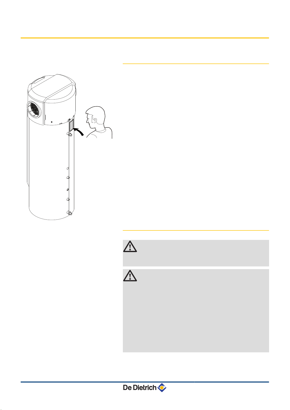
4.4.1. Type plate
4 The type plate must be accessible at all times.
4 The type plate identifies the product and provides the following
information:
- Appliance type
- Manufacturing date (Year - Week)
- Serial number.
4.4.2. Positioning of the appliance
CAUTION
When installing the appliance, respect the IP21
environmental rating.
CAUTION
4 Do not install the thermodynamic water heater in
premises exposed to gas, vapours or dust. Do not
install the thermodynamic DHW tank in an
atmosphere which is chlorinated (swimming pool) or
fluorinated (aerosols, detergents, solvents, etc.).
4 The air taken in must in no event be dusty.
4 Adequate thermal insulation in relation to adjacent
living spaces is recommended.
4 Temperature of the ambient air or of the air taken in
by the heat pump for optimum running: from 10 to
35°C.
Install the appliance in a dry, frost-free room at a minimum
4
temperature of 7°C.
4 Install the appliance on a flat, solid surface.
03/02/2014 - 300026515-001-03
19
C004021-A
C004020-A
C004019-A
A
C004022-A
C004023-A
B
4. Installation TWH 200E TWH 300E TWH 300EH
4 Install the appliance on a base frame. The base frame must at all
times present sufficient resistance to the load.
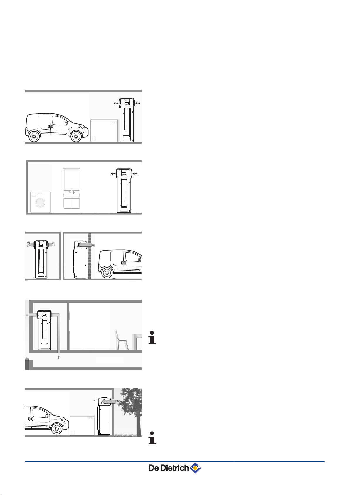
Advised positions
n
Garage:
4 Unheated room.
4 Enables recovery of the free energy released by your vehicle’s
engine when switched off after use or by household appliances in
operation.
Laundry room:
4 Unheated room.
4 Enables the dehumidification of the room and recovery of the
energy wasted by washing and drying machines.
Habitable room:
4 Can obtain free heat from the garage.
Via crawl space:
4 Connection to the crawl space is possible if the volume is greater
than 30 m3.
4 The crawl space must be frost-free (temperature > 1°C).
If the crawl space is poorly insulated, thermal losses from
the home will be greater.
Via outside air:
4 Connection to the outside air may lead to overconsumption of
electricity if the outside air temperature falls outside the operating
range.
4 Minimum distance to be observed for the ducts if intake and
backflow are done on the same façade: 700 mm.
20
Risk of discomfort in the Eco operating mode.
03/02/2014 - 300026515-001-03
 Loading...