

Page 1
Istruzioni per l'uso e l'installazione
Directions for use and instructions for installation
Notice d'utilisation et d'installation
Gebrauchs- und Installationsanweisung
Gebruiks- en installatie-aanwijzing
Instrucciones de montaje y uso
Instruçoes de uso e instalação
Cappa decorativa
Decorative hoods
Hottes décoratives
Wand-Dekorhauben
Decoratieve wandkappen
Campana
Capa de decoração
DHT386XP1
DHT496XP1
Page 2

EN
Instructions Manual
INDEX
RECOMMENDATIONS AND SUGGESTIONS....................................................................................................................15
CHARACTERISTICS............................................................................................................................................................16
INSTALLATION ....................................................................................................................................................................17
USE.......................................................................................................................................................................................19
MAINTENANCE....................................................................................................................................................................20
3
3
Page 3
EN 115
RECOMMENDATIONS AND SUGGESTIONS
INSTALLATION
• The manufacturer will not be held liable for any damages resulting
from incorrect or improper installation.
• The minimum safety distance between the cooker top and the extrac tor hood is 650 mm.
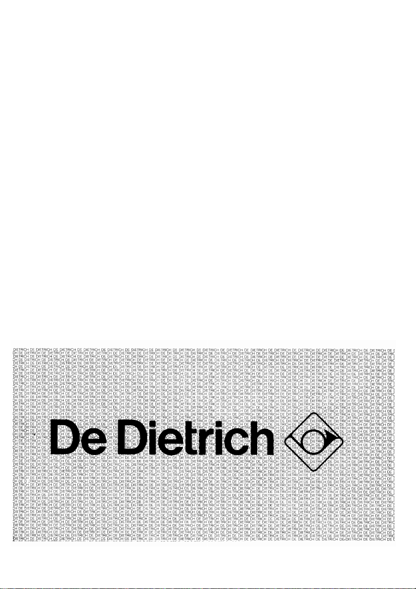
• Check that the mains voltage corresponds to that indicated on the
rating plate fixed to the inside of the hood.
• For Class I applianc es, c heck t hat th e domes tic po wer suppl y gua rantees adequate earthing.
Connect the extractor to the ex haust flue through a pi pe of minimum
diameter 120 mm. The route of the flue must be as short as possible.
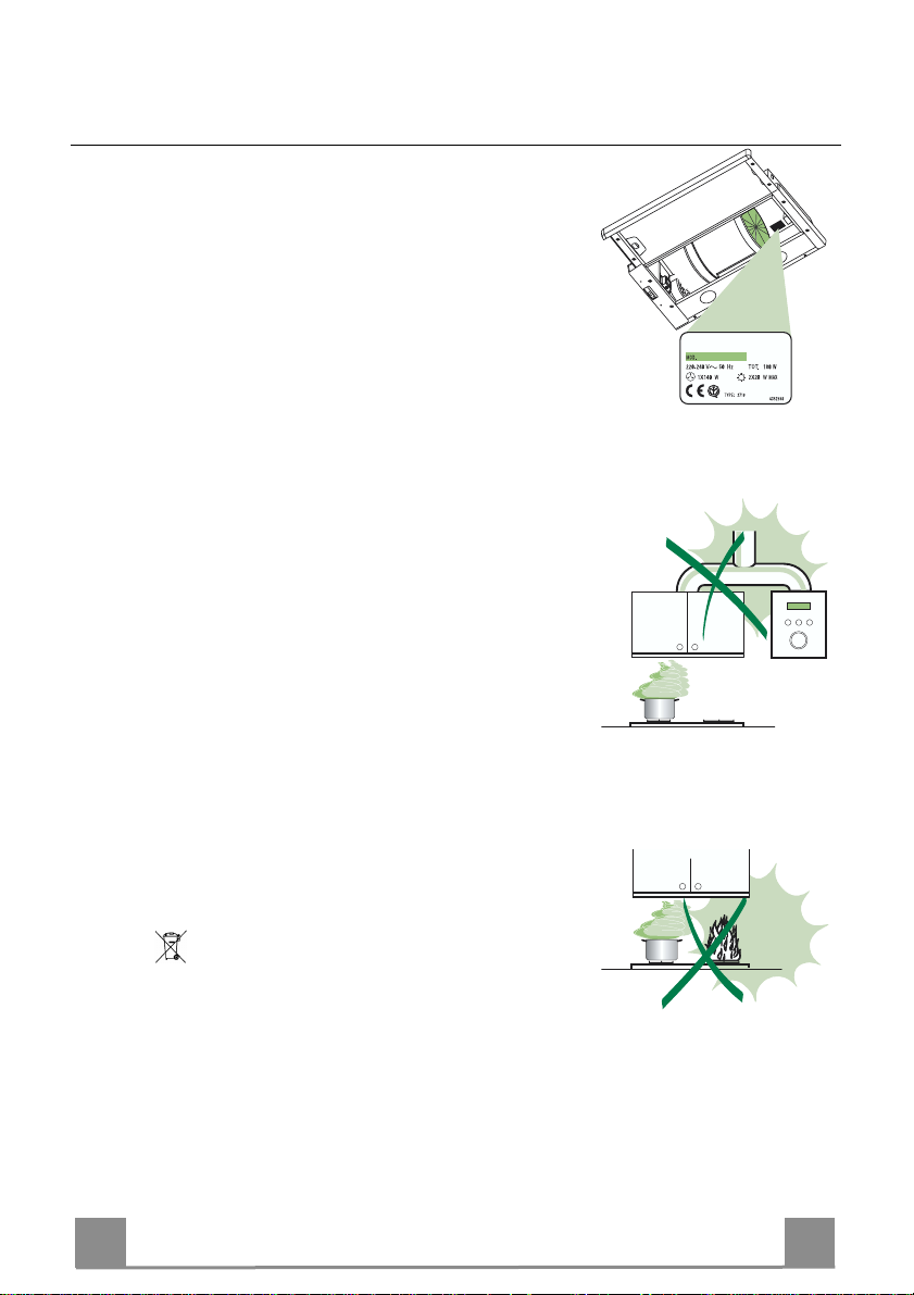
• Do not connect the extractor hood to exhaust ducts carryi ng combustion fumes (boilers, fireplaces, etc.).
• If the extractor is used in conj unction with non-electrical appliances
(e.g. gas burning appliances), a suffici ent degree of aeration must be
guaranteed in the room in order to prevent the backflow of exhaust
gas. The kitchen must have an opening communicating directl y with
the open air in order to guarantee the entry of clean air.
USE
• The extractor hood has been designe d ex cl usi vely for domesti c us e to
eliminate kitchen smells.
• Never use the hood for purposes ot her than for which it has ben designed.
• Never leave high naked flames under the hood when it is in operation.
• Adjust the flame intensity to direct it onto the bottom of the pan only,
making sure that it does not engulf the sides.
• Deep fat fryers must be continuously monitored during use: overheated oil can burst into flames.
• The hood should not be used by chil dren or persons not inst ructed in
its correct use.
MAINTENANCE
• Switch off or unplug the appliance from the mains supply before carrying out any maintenance work.
• Clean and/or replace the Filters after the specified time period.
• Clean the hood using a damp cloth and a neutral liquid detergent.
The symbol on the product or on its packaging indicates that this product
may not be treated as household waste. Instead it shall be handed over to the
applicable collection point for the recycling of electrical and electronic equipment.
By ensuring this produ ct is disposed of correctly, yo u will help preven t potential
negative consequences for the environment and human health, which could otherwise be caused by inappropriate waste handling of this product. For more detailed information about recycling of this product, please contact your local city
office, your household waste disposal service or the shop where you purchased
the product.
Page 4

EN 116
CHARACTERISTICS
ø
150
260
598 - 898
÷
0
280
152
Components
Ref. Q.ty Product Components
1 1 Hood Body, complete with: C ontrols, Light, Blower, Fil ters
8 1 Directional Air Outlet grille
9 1 Reducer Flange ø 150-120 mm
20 1 Closing element
Ref. Q.ty Installation Components
12a 4 Screws 4,2 x 44,4
12e 2 Screws 2,9 x 9,5
Q.ty Documentation
1 Instruction Manual
12e
8
9
12a
1
20
Page 5

EN 117
15
264
502 - 802
Vf
INSTALLATION
Drilling the Support surface and Fitting the Hood
SCREW FITTING
• The hood support surface must be 220 mm above the bottom
surface of the wall units.
• Drill the support with a ø 4,5 mm drill bit, using the drilling
template provided.
• Cut a hole ø 150 mm in size on the support surface, u sing the
drilling template provided.
• Fix using the 4 screws 12a (4,2 x 44,4) provided.
SNAP-ON FITTING
• The hood can be installed either directly on the bottom surface
of the wall units (min. 650 mm above the hob) using snap-on
side supports.
• Cut a fitted opening in the bottom surface of the wall unit, as
shown.
• Insert t he hood until the side supports sn ap i nto place.
• Lock in position by tightening the screws Vf from underneath
the hood.
220
CLOSING ELEMENT
• The space between the ed ge of the hood and t he rear wall can
be closed by applying the element 20 provided, using the
screws supplied for this purpose.
20
Page 6

EN 118
Connections
DUCTED VERSION AIR EXHAUST SYSTEM
When installing the ducted version, connect th e hood to
the chimney using either a flexible or rigid pipe ø 150
or 120 mm, the choice of which is left to the installer.
• To install a ø 120 mm air exhaust connection, insert
the reducer flange 9 on the hood body outlet.
• Fix the pipe in position using sufficient pipe clamps
(not supplied).
• Remove any activated charcoal filters.
ø 150
ø 120
9
RECIRCULATION VERSION AIR OUTLET
• Cut a hole ø 125 mm in any shelf that may be positioned over the hood.
• Insert t he reducer flange 9 on the hood body outlet.
• Connect the flange to t he outlet on the sh elf over the
hood using a flexible or rigid pipe ø120 mm.
• Fix the pipe in position using sufficient pipe clamps
(not supplied).
• Fix the directional grille 8 on the recirculation air
outlet using the 2 screws 12e (2,9 x 9,5) provided.
• Ensure that the activated charcoal filters have been
inserted.
ø 125
12e
8
9
ELECTRICAL CONNECTION
• Connect the hood to the mains through a two-pole switch having a contact gap of at least 3
mm.
• When opening the sliding carriage for the first time after installing the hood, pull it out
briskly until it clicks.
Page 7

EN 119
USE
Control panel
L Light Switches the li ghting system on and off.
M Motor Switches the extractor motor on and off.
V1 Speed Reduces th e operating sp eed.
V2 Speed Increases the operatin g speed.
V3 Intensive speed Maximum speed, used for eliminating the highest cooking vapour emission.
Switches off automatically after 10 minutes operation. Can also be switched off
manually by pressing the button.
S Led Fixed Motor running led
Flashing Intensive speed led.
R Receiver for Remote Control.
M L
V1 V2
V3 R
S
Page 8

EN 220
A
B
MAINTENANCE
Grease filters
CLEANING META L SELF- SUPPO RTING GREASE FILTERS
• The filters must be cleaned every 2 months of operation, or
more frequently for particularly heavy usage, and can be
washed in a dishwasher.
• Remove the filters one at a time by pushing them towards
the back of the group and pulling down at the same time.
• Wash the filters, taking care not to bend them. Allow them
to dry before refitting.
• When refitting the filters, make sure that the handle is visible
on the outside.
Activated charcoal filter (Recirculation version)
These filters are not washable and cannot be regenerated, and
must be replaced approximatel y every 4 months of operati on, or
more frequently with heavy usage.
REPLACING THE ACTIVATED CHARCOAL FILTE R
• Remove the metal grease filters
• Remove the saturated activated charcoal filter as shown (A).
• Fit the new filters (B).
• Replace the metal grease filters.
Lighting
LIGHT REPLACEMENT
20 W halogen light.
• Remove the 2 screws fixing the Lighting support, and pull it
out of from the Hood.
• Extract the lamp from the Support.
• Replace with another of the same type, making sure that the
two pins are properly inserted in the lamp holder socket holes.
• Replace the Support, fixing it in place with the two screws removed as above.
Page 9

D
Dir. 89/336/CEE
73/23/CEE
93/68/CEE
79, RUE DU GENERAL LECLERC
TEL. (1) 34 80 59 58
I E T R I C H E U R O P E E N N E D ' E L E C T R O M E N A G E R
SA A CONSEIL D'ADMINISTRATION AU CAPITAL DE F 160.100.000 RCS VERSAILLES B 352827687
FAX. (1) 34 80 58 60
B.P. 76
78403 CHATOU CEDEX
TELEX. 699 615 D E
Numéro de télép hone du servic e conso mmateurs De Di etrich : 08 92 02 88 04 (0 ,34 euros par minute) *
* Service fourni par Brandt Customer Service société par actions simplifiée au capital de 2.500.000 euros
-5/7 avenue des Béthunes,95310 Saint Ouen l’Aumône - RCS Pontoise 440 303 303
436001724_ver6
 Loading...