


® |
Powered Speaker Optimizer |
PX |
Featuring |
Powered Speakers |
User Manual |

IMPORTANT SAFETY INFORMATION
The symbols shown above are internationally accepted symbols that warn of potential hazards with electrical products. The lightning flash with arrowpoint in an equilateral triangle means that there are dangerous voltages present within the unit. The exclamation point in an equilateral triangle indicates that it is necessary for the user to refer to the owner’s manual.
These symbols warn that there are no user serviceable parts inside the unit. Do not open the unit. Do not attempt to service the unit yourself. Refer all servicing to qualified personnel. Opening the chassis for any reason will void the manufacturer’s warranty. Do not get the unit wet. If liquid is spilled on the unit, shut it off immediately and take it to a dealer for service. Disconnect the unit during storms to prevent damage.
Safety Instructions
Notice For Customers If Your Unit Is Equipped With A Power Cord.
WARNING: THIS APPLIANCE SHALL BE CONNECTED TO A MAINS SOCKET OUTLET WITH A PROTECTIVE EARTHING CONNECTION.
The cores in the mains lead are coloured in accordance with the following code:
GREEN and YELLOW - Earth BLUE - Neutral BROWN - Live
As colours of the cores in the mains lead of this appliance may not correspond with the coloured markings identifying the terminals in your plug, proceed as follows:
•The core which is coloured green and yellow must be connected to the terminal in the plug marked with the letter E, or with the earth symbol, or coloured green, or green and yellow.
•The core which is coloured blue must be connected to the terminal marked N or coloured black.
•The core which is coloured brown must be connected to the terminal marked L or coloured red.
This equipment may require the use of a different line cord, attachment plug, or both, depending on the available power source at installation. If the attachment plug needs to be changed, refer servicing to qualified service personnel who should refer to the table below. The green/yellow wire shall be connected directly to the units chassis.
CONDUCTOR |
WIRE COLOR |
|||
|
|
Normal |
Alt |
|
L |
LIVE |
BROWN |
BLACK |
|
N |
NEUTRAL |
BLUE |
WHITE |
|
E |
EARTH GND |
GREEN/ |
GREEN |
|
YEL |
||||
|
|
|
||
WARNING: If the ground is defeated, certain fault conditions in the unit or in the system to which it is connected can result in full line voltage between chassis and earth ground. Severe injury or death can then result if the chassis and earth ground are touched simultaneously.
WARNING FOR YOUR PROTECTION PLEASE READ THE FOLLOWING:
KEEP THESE INSTRUCTIONS
HEED ALL WARNINGS
FOLLOW ALL INSTRUCTIONS
The apparatus shall not be exposed to dripping or splashing liquid and no object filled with liquid, such as vases, shall be placed on the apparatus
CLEAN ONLY WITH A DRY CLOTH.
DO NOT BLOCK ANY OF THE VENTILATION OPENINGS. INSTALL IN ACCORDANCE WITH THE MANUFACTURER’S INSTRUCTIONS.
DO NOT INSTALL NEAR ANY HEAT SOURCES SUCH AS RADIATORS, HEAT REGISTERS, STOVES, OR OTHER APPARATUS (INCLUDING AMPLIFIERS) THAT PRODUCE HEAT.
ONLY USE ATTACHMENTS/ACCESSORIES SPECIFIED BY THE MANUFACTURER.
UNPLUG THIS APPARATUS DURING LIGHTNING STORMS OR WHEN UNUSED FOR LONG PERIODS OF TIME.
Do not defeat the safety purpose of the polarized or grounding-type plug. A polarized plug has two blades with one wider than the other. A grounding type plug has two blades and a third grounding prong. The wide blade or third prong are provided for your safety. If the provided plug does not fit your outlet, consult an electrician for replacement of the obsolete outlet.
Protect the power cord from being walked on or pinched particularly at plugs, convenience receptacles, and the point where they exit from the apparatus.
Use only with the cart stand, tripod bracket, or table specified by the manufacture, or sold with the apparatus. When a cart is used, use caution when moving the cart/apparatus combination to avoid injury from tip-over.
Refer all servicing to qualified service personnel. Servicing is required when the apparatus has been damaged in any way, such as power-supply cord or plug is damaged, liquid has been spilled or objects have fallen into the apparatus, the apparatus has been exposed to rain or moisture, does not operate normally, or has been dropped.
MAINS DISCONNECT: The plug shall remain readily operable. For rack-mount or installation where plug is not accessible, an all-pole mains switch with a contact separation of at least 3 mm in each pole shall be incorporated into the electrical installation of the rack or building.
FOR UNITS EQUIPPED WITH EXTERNALLY ACCESSIBLE FUSE RECEPTACLE: Replace fuse with same type and rating only.
MULTIPLE-INPUT VOLTAGE: This equipment may require the use of a different line cord, attachment plug, or both, depending on the available power source at installation. Connect this equipment only to the power source indicated on the equipment rear panel. To reduce the risk of fire or electric shock, refer servicing to qualified service personnel or equivalent.

IMPORTANT SAFETY INFORMATION
ELECTROMAGNETIC
COMPATIBILITY
This unit conforms to the Product Specifications noted on the Declaration of Conformity. Operation is subject to the following two conditions:
•this device may not cause harmful interference, and
•this device must accept any interference received, including interference that may cause undesired operation.
Operation of this unit within significant electromagnetic fields should be avoided.
•use only shielded interconnecting cables.
U.K. MAINS PLUG WARNING
A molded mains plug that has been cut off from the cord is unsafe. Discard the mains plug at a suitable disposal facility.
NEVER UNDER ANY CIRCUMSTANCES SHOULD YOU INSERT A DAMAGED OR CUT MAINS PLUG INTO A 13 AMP POWER SOCKET.
Do not use the mains plug without the fuse cover in place. Replacement fuse covers can be obtained from your local retailer. Replacement fuses are 13 amps and MUST be ASTA approved to BS1362.
If you want to dispose this product, do not mix it with general household waste. There is a separate collection system for used electronic products in accordance with legislation that requires proper treatment, recovery and recycling.
Private household in the 25 member states of the EU, in Switzerland and Norway may return their used electronic products free of charge to designated collection facilities or to a retailer (if you purchase a similar new one).
For Countries not mentioned above, please contact your local authorities for a correct method of disposal.
By doing so you will ensure that your disposed product undergoes the necessary treatment, recovery and recycling and thus prevent potential negative effects on the environment and human health.
DECLARATION OF
CONFORMITY
Manufacturer’s Name: |
dbx Professional Products |
Manufacturer’s Address: |
8760 S. Sandy Parkway |
|
Sandy, Utah 84070, USA |
declares that the product: |
|
Product name: |
DriveRack PX |
Note: Product name may be suffixed by the EU.
Product option: None
conforms to the following Product Specifications:
Safety: IEC 60065 (7th ed. 2001)
EMC: EN 55013 (2001+A1)
EN 55020 (1998)
Supplementary Information:
The product herewith complies with the requirements of the Low Voltage Directive 72/23/EEC and the EMC Directive 89/336/ EEC as amended by Directive 93/68/EEC.
Director of Engineering - dbx 8760 S. Sandy Parkway Sandy, Utah 84070, USA Date: January 23, 2008
European Contact: Your local dbx Sales and Service Office or
Harman Music Group
8760 South Sandy Parkway
Sandy, Utah 84070, USA
Ph: (801) 566-8800
Fax: (801) 568-7583

Table of Contents |
|
DriveRack® PX |
|
|
|
Section 1- Introduction.......................... |
1 |
|
0.1 |
Defining the DriveRack PX............... |
1 |
0.2 |
Service Contact Info....................... |
2 |
0.3 |
Warranty....................................... |
3 |
Section 2- Getting Started...................... |
4 |
|
2.1 |
Rear Panel Connections................... |
4 |
2.2 |
Front Panel Connections.................. |
4 |
2.3 |
Quick Start.................................... |
6 |
2.4 |
DriveRack PX Wizard....................... |
8 |
Section 3 - Editing Functions.................. |
15 |
|
3.1 |
Basic Navigation Modes................... |
15 |
3.2 |
Button Array Overview.................... |
15 |
3.3 |
Navigating the High-pass and |
|
|
Bandpass Filter (SETUP) Section....... |
16 |
3.4 |
Navigating the |
|
|
Subharmonic Section...................... |
16 |
3.5 |
Navigating the |
|
|
Comp/Limiter Section..................... |
17 |
3.6 |
Navigating the EQ Section............... |
17 |
3.7 |
Navigating the AFS Section.............. |
18 |
3.8 |
Navigating the Utility Section.......... |
18 |
3.9 |
Navigating the Wizard Section.......... |
18 |
3.10 Navigating the Recall Section......... |
19 |
|
3.11 Navigating the Store Section.......... |
19 |
|
Section 4 - Operating Functions............... |
20 |
|
4.1 |
Preset Definition............................ |
20 |
4.2 |
Navigating Factory Presets............... |
20 |
4.3 |
Editing Factory Presets.................... |
21 |
Section 5 - Detailed Parameters................ |
23 |
|
5.1 |
Stereo Input Graphic EQ.................. |
23 |
5.2 |
AFS (Automatic Feedback |
|
Suppression)....................................... |
23 |
|
5.3 |
Subharmonic Synthesizer................. |
25 |
5.4 |
Compressor/Limiter......................... |
26 |
5.5 |
Filter (SETUP)............................... |
28 |
5.6 |
Output Parametric EQ (3-band)......... |
28 |
Section 6 - Application Guide.................... |
29 |
|
6.1 |
Mains-Only Setup (No Subs)............. |
29 |
6.2 |
Two Mains/One Subwoofer Setup...... |
30 |
6.3 |
Two Mains/Two Subwoofers Setup..... |
31 |
6.4 |
Sub with Satellites Setup................ |
32 |
Section A - Appendix............................... |
33 |
|
A.1 |
Factory Reset................................ |
33 |
A.2 |
Power Up Quick Key Options............ |
33 |
A.3 |
Specifications................................ |
35 |
A.4 |
Auto-EQ Optimization Tips............... |
36 |
A.5 |
Crossover Diagrams......................... |
36 |
A.6 |
Block Diagram............................... |
37 |
A.7 |
Preset List / Supported Speakers...... |
38 |
A.8 |
System Setup and Gain Structure...... |
39 |
®

|
DriveRack® PX |
|
Introduction |
Section 1 |
|
|
|
||||
|
|
|
|
|
|
Section 1- Introduction
The dbx DriveRack® PX Powered Speaker Optimizer has everything you need to get the most out of your stereo powered speaker system. It even includes stereo or mono subwoofer support. With the included dbx M2 measurement mic, Auto-EQ corrects for audible deficiencies in the room environment. Our patented Advanced Feedback Suppression (AFS™) kills nasty feedback, allowing problem-free operation at higher sound levels, while our patented Subharmonic Synthesizer™ extends bass response for enhanced bottom end. With all that, you also get classic dbx compression and the protection offered by our graceful PeakPlusTM limiting. Your ears, your audience, and your powered speakers will forever thank you.
0.1 Defining the DriveRack PX
The dbx DriveRack PX is the most effective way to manage all aspects of powered loudspeaker management for public address system applications. The DriveRack PX essentially becomes the only device that you will need between the mixer and the powered speakers. The following are just some of the features of the DriveRack PX.
DriveRack® PX features:
•Stereo Feedback Elimination with 12 feedback notch filters
•Stereo 28-band Graphic EQ
•Classic dbx® Compressor
•120A Subharmonic Synthesizer
•Stereo Multi-band Parametric EQ
•Stereo PeakPlus™ Limiters
•Pink Noise Generator
•Auto-EQTM with 28-Band RTA
•JBL® and other popular powered speakers included in Setup Wizard
•JBL® preset speaker combinations
•dbx M2 Measurement Mic and zippered pouch included
•Front panel RTA-Mic XLR input with phantom power
•25 User Programs / 25 Factory Programs
•2 Channel XLR Input
•2 Channel XLR Output
•2 Channel XLR Sub Output
•24-Bit ADC/24-Bit DAC, >110 dB Dynamic Range
•dbx Type IVTM Conversion System
•Full Graphic LCD Display
By including every form of processing necessary to drive the signal from the mixer to the power amp, the DriveRack® PX allows you to eliminate all other processing devices normally found in large and cumbersome traditional drive rack systems of the past.
The DriveRack PX Powered Speaker Optimizer includes two balanced XLR inputs and two balanced XLR outputs, as well as two balanced XLR subwoofer output connectors.
® |
|
|
|
|
|

Section 1 Introduction |
|
DriveRack® PX |
|
|
|
0.2 Service Contact Info
If you require technical support, contact dbx Customer Service. Be prepared to accurately describe the problem. Know the serial number of your unit - this is printed on a sticker attached to the bottom panel. If you have not already taken the time to fill out your warranty registration card and send it in, please do so now.
Before you return a product to the factory for service, we recommend you refer to the manual. Make sure you have correctly followed installation steps and operation procedures. If you are still unable to solve a problem, contact our Customer Service Department at (801) 568-7660 for consultation. If you need to return a product to the factory for service, you MUST first contact Customer Service to obtain a Return Authorization Number.
No returned products will be accepted at the factory without a Return Authorization Number.
Please refer to the Warranty information on the following page, which extends to the first end-user. After expiration of the warranty, a reasonable charge will be made for parts, labor, and packing if you choose to use the factory service facility. In all cases, you are responsible for transportation charges to the factory. dbx will pay return shipping if the unit is still under warranty.
Use the original packing material if it is available. Mark the package with the name of the shipper and with these words in red: DELICATE INSTRUMENT, FRAGILE! Insure the package properly. Ship prepaid, not collect. Do not ship parcel post.
|
® |

|
DriveRack® PX |
|
Introduction |
Section 1 |
|
|
|
||||
|
|
|
|
|
|
0.3 Warranty
This warranty is valid only for the original purchaser and only in the United States.
1.The warranty registration card that accompanies this product must be mailed within 30 days after purchase date to validate this warranty. Proof-of-purchase is considered to be the burden of the consumer.
2.dbx warrants this product, when bought and used solely within the U.S., to be free from defects in materials and workmanship under normal use and service.
3.dbx liability under this warranty is limited to repairing or, at our discretion, replacing defective materials that show evidence of defect, provided the product is returned to dbx WITH RETURN AUTHORIZATION from the factory, where all parts and labor will be covered up to a period of two years. A Return Authorization number must first be obtained from dbx by telephone. The company shall not be liable for any consequential damage as a result of the product’s use in any circuit or assembly.
4.dbx reserves the right to make changes in design or make additions to or improvements upon this product without incurring any obligation to install the same additions or improvements on products previously manufactured.
5.The foregoing is in lieu of all other warranties, expressed or implied, and dbx neither assumes nor authorizes any person to assume on its behalf any obligation or liability in connection with the sale of this product. In no event shall dbx or its dealers be liable for special or consequential damages or from any delay in the performance of this warranty due to causes beyond their control.
® |
|
|
|
|
|

Section 2 Getting Started |
|
DriveRack® PX |
|
|
|
Section 2- Getting Started
2.1 Rear Panel Connections
|
|
|
SUB OUTPUTS |
|
|
|
GND |
R |
PX |
|
Manufactured under the following U.S. Patents: |
|
UL 60065 |
IEC 60065 |
3,789,143; 4,182,993; 6,195,029; 7,203,324. |
|
120V - 60Hz |
|
IEC Power Cord Receptacle
The DriveRack® PX comes with a power supply that will accept voltages ranging from 100V120V at frequencies from 50Hz-60Hz. An IEC cord is included. EU versions accept 220V-240V at frequencies from 50Hz-60Hz.
Sub Outputs Left/Mono and Right
Connect your subwoofer(s) here (optional).
Outputs Left and Right
Connect your main speakers here.
Inputs Left/Mono and Right
The input section of the DriveRack PX offers two electronically balanced XLR connectors.
Ground Lift Switch
The ground lift switch lifts the pin 1 chassis ground of both input XLR connectors.
+4dBu / –10dBV Switch
This switch selects between –10dBV and +4dBu nominal operating levels. When the switch is in the “in” position, the –10dBV operating level is selected. When the switch is in the “out” position, +4dBu is selected.
2.2 Front Panel Connections
PREV PG |
NEXT PG |
SETUP |
Inputs |
Outputs |
Sub Outs |
|
|
|
|
|
Limiter |
|
|
|
Headroom dB |
Headroom dB |
Headroom dB |
|
|
|
6 |
6 |
6 |
DriveRack®PX |
SUBHARMONIC |
COMP/LIMITER |
EQ |
0 |
0 |
0 |
|
|
|
|
12 |
12 |
12 |
Powered Speaker |
PRESET |
STORE |
AFS |
24 |
24 |
24 |
Optimizer |
|
|
|
36 |
36 |
36 |
|
|
|
|
SIG |
SIG |
SIG |
|
RECALL |
UTILITY |
WIZARDI |
|
|
|
|
RTA Mic Input Jack
This balanced XLR input is used for the connection of the dbx M2 RTA microphone, which allows the user to optimize the powered speaker settings and the EQ settings of any room through the use of the System Setup and Auto-EQ Wizards.
RTA MIC Input Selector
Pressing the RTA MIC input button will engage the front panel RTA input XLR connector and start the Auto-EQ wizard.
|
® |

|
DriveRack® PX |
|
Getting Started |
Section 2 |
|
|
|
||||
|
|
|
|
|
|
Data Wheel
The Data wheel of the DriveRack® PX is used to scroll through the preset menu, load presets, select parameters and edit parameter values.
LCD Display
The backlit LCD display of the DriveRack® PX provides the user with all of the vital processing information of the DriveRack® PX including: signal routing, effect block editing and Wizard functions. The display will also notify the user if any internal clipping is taking place within the unit. The following message will appear: CLIP.
Function Buttons
The function buttons of the DriveRack® PX allow direct access to all editing and navigating functions of the DriveRack® PX. The functions of the aforementioned buttons are as follows:
<PREV PG> - Moves to the previous page in the currently selected menu. <NEXT PG> - Moves to the next page in the currently selected menu.
<SETUP> - Press and release to enter the high-pass and bandpass filter editor. Press and hold to enter the first page of the Powered Speaker Setup Wizard.
<SUBHARMONIC> - Press and release to enter the dbx 120A Subharmonic Synthesizer editor. <COMP/LIMITER> - Press and release to cycle through the compressor editor and output limiter processing editor.
<EQ> - Press and release to cycle through the graphic EQ and parametric EQ editors. Press and hold to enter the first page of the Auto-EQ Wizard.
<PRESET/[RECALL]> - Press and release to return to the preset view, showing preset number, preset bank (user or factory), preset name, and signal path. Press and hold to activate the [RECALL] button function which allows the selection and loading of a new preset. <STORE/[UTILITY]> - Press and release to enter the Store menu, which allows the user to store the current state to a user preset. Press and hold to enter the UTILITY menu to adjust LCD contrast, Auto-EQ plot selection (RTA or GEQ), and Sales Banner on/off.
<AFS> - Press and release to enter the AFS editor. Press and hold to enter the first page of the AFS Wizard.
Stereo Input Meters
The DriveRack® PX provides the user with two independent six segment input meters that range from Signal Present (–48 dBFS) to 0 dBFS (maximum output). These meters monitor the signal level right after the input module.
Stereo Output Meters
The DriveRack® PX provides the user with two independent six-segment output meters that range from Signal Present to 0 dBFS (maximum output).
Mono/Stereo Subwoofer Output Meters
The DriveRack® PX provides the user with two independent six-segment subwoofer output meters that range from Signal Present to 0 dBFS (maximum output).
Threshold Meters
The threshold meters indicate that the threshold level has been exceeded within the Limiter section, and gain reduction may be taking place within the specific output channel.
® |
|
|
|
|
|
Section 2 Getting Started |
|
DriveRack® PX |
|
|
|
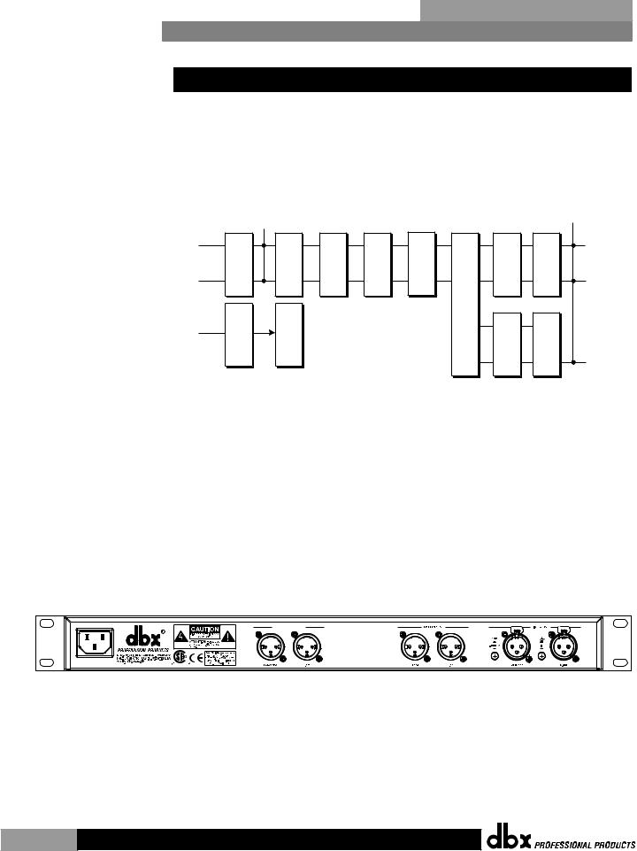
2.3 Quick Start
For those of you that wish to jump right in, the following information has been provided to act as a quick start guide for optimizing performance of the DriveRack® PX.
Signal Path Block Diagram
The following diagram shows the logical and intuitive signal path of the input, signal processing modules, and output of the DriveRack® PX.
Meters Outputs
Meters
Left (Mono) Input
Right Input
Mic Input
Micr Pre amp Stereo/Mono Pink Noise |
RTA GEQ |
AFS Notch Filters |
SubHarmonic Synth |
Stereo Compressor |
High-Pass and Band-Pass Filter Section |
2-Band PEQ 3-Band PEQ |
PeakPlus Limiter PeakPlus Limiter |
 Left
Left
 Right
Right
Sub Outputs
 Left (Mono)
 Right
Right
Connections
•When setting up the DriveRack® PX, make connections as follows:
•Always make connections prior to applying power to the unit.
•Connect the output from the sending device (mixer) to one or both of the two XLR input connectors shown below.
•Make output connections from “Outputs” XLR connectors shown below to the inputs of the powered speakers.
•If a subwoofer or subwoofers are to be used, make output connections from “Sub Outputs” XLR connectors shown below to the inputs of the subwoofers.
|
|
|
SUB OUTPUTS |
|
|
|
GND |
R |
PX |
|
Manufactured under the following U.S. Patents: |
|
UL 60065 |
IEC 60065 |
3,789,143; 4,182,993; 6,195,029; 7,203,324. |
|
120V - 60Hz |
|
•If you will be “pinking” the room through the use of the RTA, connect the dbx M2 RTA microphone to the front-panel XLR input.
•IMPORTANTIt is imperative that the powered speakers are turned off prior to applying power to the DriveRack® PX. Always make sure that your powered speakers are the last item turned on and the first turned off.
|
® |
|
DriveRack® PX |
|
Getting Started |
Section 2 |
|
|
|
||||
|
|
|
|
|
|
Once all of the connections have been made and the unit is powered up, you can navigate through the entire signal path of the DriveRack PX from the front panel of the unit. The display provides you with a clear and concise overview of each aspect of the signal path from the input to the output section.
PREV PG |
NEXT PG |
SETUP |
Inputs |
Outputs |
Sub Outs |
|
|
|
|
|
Limiter |
|
|
|
Headroom dB |
Headroom dB |
Headroom dB |
|
|
|
6 |
6 |
6 |
DriveRack®PX |
SUBHARMONIC |
COMP/LIMITER |
EQ |
0 |
0 |
0 |
|
|
|
|
12 |
12 |
12 |
Powered Speaker |
PRESET |
STORE |
AFS |
24 |
24 |
24 |
Optimizer |
|
|
|
36 |
36 |
36 |
|
|
|
|
SIG |
SIG |
SIG |
|
RECALL |
UTILITY |
WIZARDI |
|
|
|
|
The features of the front panel of the DriveRack® PX are as follows from left to right.
RTA MIC Input - This XLR input is used for the connection of the dbx M2 RTA microphone (included). The RTA MIC input button is used to engage the RTA input connector.
LCD Display - All operational information of the DriveRack® PX is displayed here. The display will also notify the user if any internal clipping is taking place within the unit. The following message will appear: CLIP.
Data Wheel - The data wheel is used to scroll through the preset menu of the DriveRack® PX. The Data Wheel is also used to perform editing functions to signal processing and utility menu features.
Button Array - Operational editing is done using this 9 button array. A complete description of each button’s functionality is listed on page 5.
Input meters - These two 6-segment LED meters monitor the input level of the DriveRack® PX directly after the input mixer.
Output Meters - These two 6-segment meters monitor the output levels of the DriveRack® PX directly after the output gain stage.
Subwoofer Output Meters - These two 6-segment meters monitor the subwoofer output levels of the DriveRack® PX directly after the output gain stage.
Threshold Meters - These four 1-segment meters indicate when the threshold levels of the limiters have been exceeded.
PREV PG |
NEXT PG |
SETUP |
SUBHARMONIC |
COMP/LIMITER |
EQ |
PRESET |
STORE |
AFS |
RECALL |
UTILITY |
WIZARD |
® |
|
|
|
|
|
Section 2 Getting Started |
|
DriveRack® PX |
|
|
|
2.4 DriveRack PX Wizard
Now that you have made all of your audio connections and have made yourself familiar with the front-panel navigation of the unit, you can easily optimize your system through the use of the DriveRack® PX Wizards. These allow for quick and accurate venue setups. There are three wizards: Setup, EQ, and AFS. Press hold any button in the Wizard section of the front panel to access them. The wizards are designed to be used in sequence (from top to bottom), but can be used individually as well.
Before you use the wizards, make sure the controls on your powered speakers are set the same on both speakers. For example, if you’re using subs, and they have a polarity setting, make sure they’re both set to the same polarity. Also, if your powered speakers have a Mic/Line setting, make sure they’re both set to Line, and if they have their own EQ settings, disable the EQ settings on the powered speakers.
The following section walks you through each of the wizards.
Setup Wizard
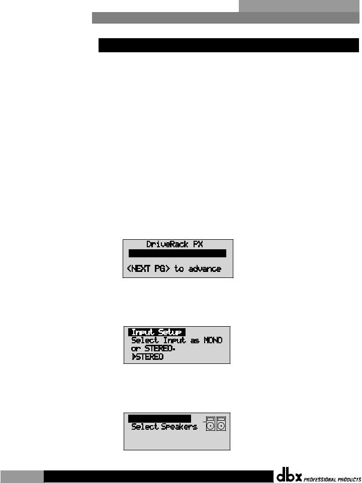
•From preset mode, press and hold the <SETUP> button and the display will appear as follows:
System Setup WIZARD
Press the <Next PG> button to continue.
•The display will appear as follows:
•Simply rotate the <Data> wheel to select either a Mono or Stereo input configuration. Once you have selected your input option, press the <NEXT PG> button and the display will appear as follows:
Main Speakers
JBL EON
 EON10G2
|
® |
|
DriveRack® PX |
|
Getting Started |
Section 2 |
|
|
|
||||
|
|
|
|
|
|
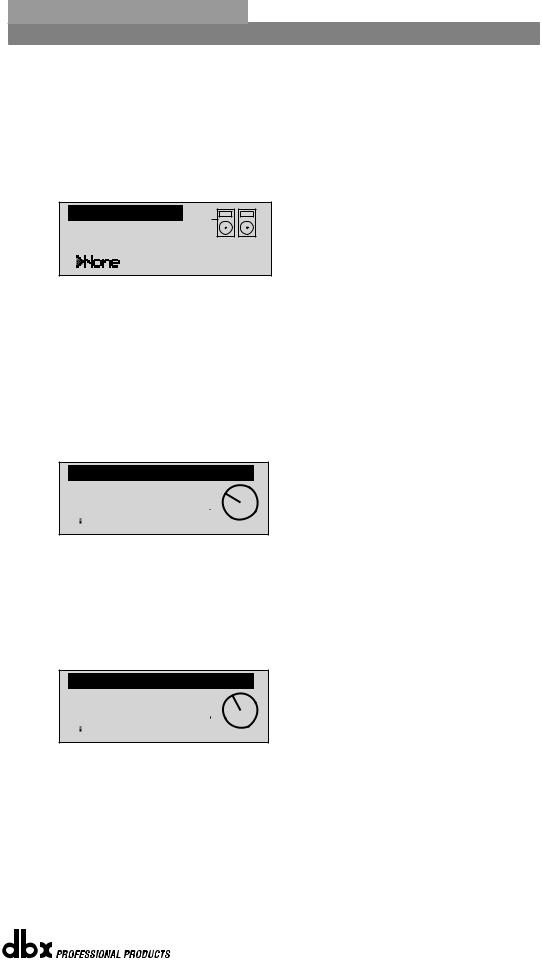
•Rotate the <Data> wheel to select any one of the numerous MAIN speaker options available. If the speaker being used is not specified in the menu, select CUSTOM. (Note that you can scroll by category by pressing the Select knob and placing the arrow next to the category heading above the speaker name. Press the Select knob again to place the arrow next to the speaker name to scroll by speaker name.) Once you have selected your Main speaker option, press the <NEXT PG> button and the display will appear as follows:
Sub Speakers
Select Sub(s)
•Rotate the <Data> wheel to select any one of the numerous SUB speaker options available. (Note that you can scroll by category by pressing the Select knob and placing the arrow next to the category heading above the speaker name. Press the Select knob again to place the arrow next to the speaker name to scroll by speaker name.) Once you have selected your SUB speaker option, press the <NEXT PG> button.
•You will now be given the option of optimizing your main speakers’ levels with the DriveRack PX. The page will appear something like this:
Main Speaker Levels Adjust speaker levels as shown
>

 31% Level
•Turn the volume (level) knob on each of your main powered speaker(s) to the position shown in this screen. When you’ve done this, press the <NEXT PG> button.
•If you’re using sub speaker(s), you will now be given the option of optimizing your sub speakers’ levels with the DriveRack PX. The page will appear something like this:
Sub Speaker Levels Adjust speaker levels as shown
>

 40% Level
•Turn the volume (level) knob on each of your sub speakers to the position shown in this screen. When you’ve done this, press the <NEXT PG> button. (If you’re not using sub speakers, this step will be skipped.)
•The display will now prompt you to load the preset you’ve just created.
® |
|
|
|
|
|
Section 2 Getting Started |
|
DriveRack® PX |
|
|
|
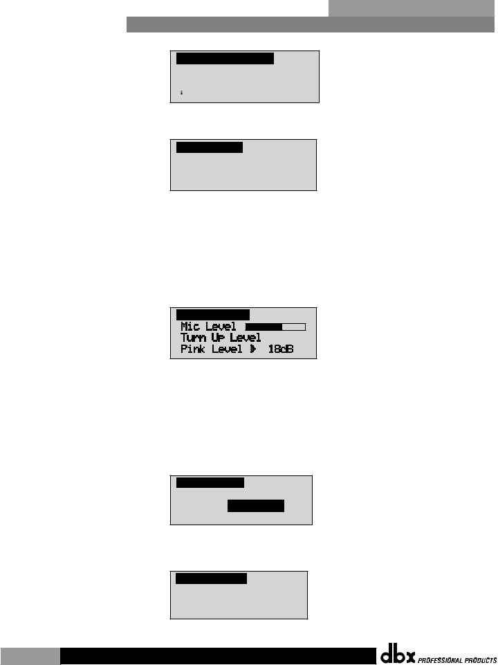
Load New Preset
Press Select to Load
>

 New Preset
•Press the <Data> wheel to load the new preset. The display will look like this:
Auto Level
Connect mic to RTA input. Press RTA input button.
•The display is prompting you to connect an RTA-specific microphone to the front-panel RTA XLR input, and press the <RTA Input> button. It is recommended that you use the included dbx M2 RTA microphone, placed somewhere close to the middle of where your audience will be. (If you wish to manually balance the individual speaker levels by ear, you can skip the Auto Level portion of this wizard, by pressing the <Preset> button.)
Once you’ve connected the RTA microphone and pressed the <RTA Input> button, the display will look like this:
Auto Level
•You will now proceed to “Pink” the room by adjusting the Pink level. The range of bar graph is -Inf dB to +20dB. Be certain to raise the pink noise level to the level of
loudness intended during the performance. Once the Pink level has been adjusted to the desired volume, press the <Next Pg> button and the Auto Level sequence will begin. The DriveRack PX will adjust balance levels for your main speakers (and your subs, if you have them). Note that you may be prompted to readjust the your speaker knob settings. When the Auto Level sequence is finished, the display will look like this:
Auto Level Complete
Release RTA INPUT button to exit.
•After you press the <RTA Input> button to release it, the display will look something like this:
EON10g2wSub Loaded and levels balanced. <NEXT PG>-Auto EQ <PRESET)-Exit Wizard
Press the <Next PG> button to start the Auto-EQ wizard.
10 |
® |
|
DriveRack® PX |
|
Getting Started |
Section 2 |
|
|
|
||||
|
|
|
|
|
|
Auto-EQ WIZARD
•Once you have completed the Setup wizard, you can now proceed to EQ your system. The Auto-EQ Wizard automatically adjusts the response of the system by producing pink noise and adjusting the Graphic EQ until the RTA matches a selected response. (The Auto-EQTM Wizard can be initialized at any time by pressing and holding the <EQ> button.) The display will look like this:
DriveRack PX
Auto EQ WIZARD
<NEXT PG> to advance
•Press the <NEXT PG> button and the display will read:
Auto EQ
Connect mic to RTA input. Press RTA input button.
•The display is prompting you to connect an RTA-specific microphone to the front-panel RTA XLR input, and press the <RTA Input> button. It is recommended that you use the included dbx M2 RTA microphone. The display will appear something like this:
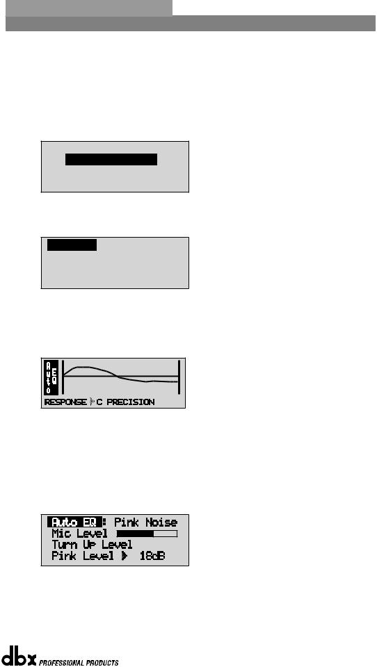
MED |
•You can now select any one of the several different Frequency responses for the Auto-EQ. The options are: Flat (0), and Responses A-D. You can also select Low, Medium and High Precision. Press the <Data Wheel> to toggle between selecting Response and Precision.
Turn the <Data Wheel> to scroll through the available options. Once you have selected your desired EQ Frequency response, press the <Next pg> button and the display will appear as follows:
•You will now proceed to “Pink” the room by adjusting the Pink level. The range of bar graph is –INF to +20dBu. Be certain to raise the pink noise level to the level of loudness intended during the performance. Once the Pink level has been adjusted to the desired volume, press the <Next pg> button and the Auto-EQ sequence will begin. The display will
® |
|
11 |
|
|
|
 Loading...