


® |
Complete Equalization & Loudspeaker Management System |
4800/4820 |
User Manual |
IMPORTANT SAFETY INSTRUCTIONS
C A U T I O N |
RISK OF ELECTRIC SHOCK |
DO NOT OPEN |
ATTENTION: RISQUE DE CHOC ELECTRIQUE - NE PAS OUVRIR |
WARNING: TO REDUCE THE RISK OF FIRE OR ELECTRIC
SHOCK DO NOT EXPOSE THIS EQUIPMENT TO RAIN OR MOISTURE
The symbols shown above are internationally accepted symbols that warn of potential hazards with electrical products. The lightning flash with arrowpoint in an equilateral triangle means that there are dangerous voltages present within the unit. The exclamation point in an equilateral triangle indicates that it is necessary for the user to refer to the owner’s manual.
These symbols warn that there are no user serviceable parts inside the unit. Do not open the unit. Do not attempt to service the unit yourself. Refer all servicing to qualified personnel. Opening the chassis for any reason will void the manufacturer’s warranty. Do not get the unit wet. If liquid is spilled on the unit, shut it off immediately and take it to a dealer for service. Disconnect the unit during storms to prevent damage.
SAFETY INSTRUCTIONS
NOTICE FOR CUSTOMERS IF YOUR UNIT IS EQUIPPED WITH A POWER CORD.
WARNING: THIS APPLIANCE MUST BE EARTHED. CONNECT ONLY TO A MAINS SOCKET OUTLET WITH PROTECTIVE EARTHING CONNECTION.
The cores in the mains lead are coloured in accordance with the following code:
GREEN andYELLOW - Earth BLUE - Neutral BROWN - Live
As colours of the cores in the mains lead of this appliance may not correspond with the coloured markings identifying the terminals in your plug, proceed as follows:
•The core which is coloured green and yellow must be connected to the terminal in the plug marked with the letter E, or with the earth symbol, or coloured green, or green and yellow.
•The core which is coloured blue must be connected to the terminal marked N or coloured black.
•The core which is coloured brown must be connected to the terminal marked L or coloured red.
This equipment may require the use of a different line cord, attachment plug, or both, depending on the available power source at installation. If the attachment plug needs to be changed, refer servicing to qualified service personnel who should refer to the table below. The green/yellow wire shall be connected directly to the units chassis.
CONDUCTOR |
WIRE COLOR |
||
|
|
Normal |
Alt |
L |
LIVE |
BROWN |
BLACK |
N |
NEUTRAL |
BLUE |
WHITE |
E |
EARTH GND |
GREEN/YEL |
GREEN |
WARNING: If the ground is defeated, certain fault conditions in the unit or in the system to which it is connected can result in full line voltage between chassis and earth ground. Severe injury or death can then result if the chassis and earth ground are touched simultaneously.
WARNING FOR YOUR PROTECTION
READ THESE INSTRUCTIONS:
KEEP THESE INSTRUCTIONS
HEED ALL WARNINGS
FOLLOW ALL INSTRUCTIONS
THE APPARATUS SHALL NOT BE EXPOSED TO DRIPPING OR SPLASHING LIQUID AND NO OBJECT FILLED WITH LIQUID, SUCH AS VASES, SHALL BE PLACED ON THE APPARATUS.
CLEAN ONLY WITH A DRY CLOTH.
DO NOT BLOCK ANY OF THE VENTILATION OPENINGS. INSTALL IN ACCORDANCE WITH THE MANUFACTURER’S INSTRUCTIONS.
DO NOT INSTALL NEAR ANY HEAT SOURCES SUCH AS RADIATORS, HEAT REGISTERS, STOVES, OR OTHER APPARATUS (INCLUDING AMPLIFIERS) THAT PRODUCE HEAT.
ONLY USE ATTACHMENTS/ACCESSORIES SPECIFIED BY THE MANUFACTURER.
UNPLUG THIS APPARATUS DURING LIGHTNING STORMS OR WHEN UNUSED FOR LONG PERIODS OF TIME.
Do not defeat the safety purpose of the polarized or grounding-type plug. A polarized plug has two blades with one wider than the other. A grounding type plug has two blades and a third grounding prong. The wide blade or third prong are provided for your safety. If the provided plug does not fit your outlet, consult an electrician for replacement of the obsolete outlet.
Protect the power cord from being walked on or pinched particularly at plugs, convenience receptacles, and the point where they exit from the apparatus.
Use only with the cart stand, tripod bracket, or table specified by the manufacture, or sold with the apparatus. When a cart is used, use caution when moving the cart/apparatus combination to avoid injury from tip-over.
Refer all servicing to to qualified service personnel. Servicing is required when the apparatus has been damaged in any way, such as power-supply cord or plug is damaged, liquid has been spilled or objects have fallen into the apparatus, the apparatus has been exposed to rain or moisture, does not operate normally, or has been dropped.
POWER ON/OFF SWITCH: For products provided with a power switch, the power switch DOES NOT break the connection from the mains.
MAINS DISCONNECT: The plug shall remain readily operable. For rackmount or installation where plug is not accessible, an all-pole mains switch with a contact separation of at least 3 mm in each pole shall be incorporated into the electrical installation of the rack or building.
FOR UNITS EQUIPPED WITH EXTERNALLY ACCESSIBLE FUSE RECEPTACLE: Replace fuse with same type and rating only.
MULTIPLE-INPUT VOLTAGE: This equipment may require the use of a different line cord, attachment plug, or both, depending on the available power source at installation. Connect this equipment only to the power source indicated on the equipment rear panel. To reduce the risk of fire or electric shock, refer servicing to qualified service personnel or equivalent.
This Equipment is intended for rack mount use only.

IMPORTANT SAFETY INSTRUCTIONS
ELECTROMAGNETIC
COMPATIBILITY
This unit conforms to the Product Specifications noted on the Declaration of Conformity. Operation is subject to the following two conditions:
•this device may not cause harmful interference, and
•this device must accept any interference received, including interference that may cause undesired operation.
Operation of this unit within significant electromagnetic fields should be avoided.
•use only shielded interconnecting cables.
U.K. MAINS PLUG WARNING
A molded mains plug that has been cut off from the cord is unsafe. Discard the mains plug at a suitable disposal facility. NEVER UNDER ANY CIRCUMSTANCES SHOULD YOU INSERT A DAMAGED OR CUT MAINS PLUG INTO A 13 AMP POWER SOCKET. Do not use the mains plug without the fuse cover in place. Replacement fuse covers can be obtained from your local retailer. Replacement fuses are 13 amps and MUST be ASTA approved to BS1362.
DECLARATION OF
CONFORMITY
Manufacturer's Name: dbx Professional Products Manufacturer's Address: 8760 S. Sandy Parkway
Sandy, Utah 84070, USA
declares that the product:
Product name: |
dbx 4800 and dbx 4820 |
Note: Product name may be suffixed by the |
|
letters-EU. |
|
Product option: |
Digital Audio Network |
Card conforms to the following Product |
|
Specifications: |
|
Safety: |
IEC 60065 (1998) |
EMC: |
EN 55013 (2001+A1) |
|
EN 55020 (2002+A1) |
Supplementary Information:
The product herewith complies with the requirements of the Low Voltage Directive 73/23/EEC and the EMC Directive 89/336/EEC as amended by Directive 93/68/EEC.
Vice-President of Engineering - Pro
8760 S. Sandy Parkway
Sandy, Utah 84070, USA
Date:April 15, 2005
European Contact:
Your local dbx Sales and Service Office or
Harman Music Group
8760 South Sandy Parkway
Sandy, Utah 84070, USA
Ph: (801) 566-8800
Fax: (801) 568-7583

|
|
|
|
|
|
® |
|
|
Table of Contents |
|
DriveRack |
||
|
|
|
|
|
||
Introduction |
|
Section 6 - Detailed Parameters |
||||
0.1 |
DriveRack 4800/4820 Features ............................. |
ii |
6.1 |
Input Mixer......................................................... |
40 |
|
0.2 |
Service Contact Info............................................. |
iii |
6.2 |
Input Router ....................................................... |
41 |
|
0.3 Warranty .............................................................. |
iii |
6.3 |
Input Graphic EQ............................................... |
42 |
||
Section 1 - Getting Started |
|
6.4 |
Input 9-Band Parametric EQ .............................. |
43 |
||
|
6.5 |
Input Delay ......................................................... |
44 |
|||
1.1 |
Rear Panel 4800/4820........................................... |
2 |
6.6 |
Output Mixer...................................................... |
45 |
|
1.2 |
Front Panel (4800) ................................................ |
3 |
6.7 |
Output Router .................................................... |
46 |
|
1.3 |
Front Panel (4820) ................................................ |
5 |
6.8 |
Output Bandpass Filter/Crossover ....................... |
47 |
|
1.4 |
System Architect Control Software........................ |
6 |
6.9 |
Output 6-Band Parametric EQ ........................... |
48 |
|
Section 2 - DriveRack 4800/4820 |
6.10 |
Output Delay .................................................... |
49 |
|||
6.11 |
Advanced Feedback Suppression (AFS®) Insert.. |
50 |
||||
Philosophy |
|
6.12 |
Automatic Gain Control (AGC) Insert.............. |
52 |
||
2.1 |
DriveRack 4800/4820 Philosophy....................... |
10 |
6.13 |
AutoWarmth® Insert.......................................... |
54 |
|
Section 3 - Front Panel Operation |
6.14 |
Compressor Insert ............................................. |
55 |
|||
6.15 |
De-Esser Insert .................................................. |
57 |
||||
3.1 |
Navigation........................................................... |
12 |
6.16 |
Noise Gate ........................................................ |
58 |
|
3.2 |
Modes of Operation ............................................ |
13 |
6.17 |
Limiter Insert .................................................... |
59 |
|
Section 4 - Software Operation |
|
6.18 |
Notch Filter Insert............................................. |
61 |
||
|
6.19 |
SubHarmonic Synthesizer Insert........................ |
62 |
|||
4.1 |
DriveRack Philosophy ......................................... |
20 |
Section 7 - Utilities |
|
||
4.2 |
System Architect DriveRack 4800/4820 |
|
|
|||
|
File Storage ......................................................... |
20 |
7.1 |
Miscellaneous ...................................................... |
64 |
|
4.3 |
System Architect DriveRack 4800/4820 |
|
7.2 |
Gains and Trims .................................................. |
64 |
|
|
Philosophy .......................................................... |
20 |
7.3 |
Sample Rate ........................................................ |
64 |
|
4.3.1 Module View ................................................... |
20 |
7.4 |
Real Time Clock.................................................. |
65 |
||
4.3.2 Device Window................................................ |
21 |
7.5 |
Access Rights....................................................... |
65 |
||
4.3.3 Venue View ...................................................... |
25 |
7.6 |
Users ................................................................... |
65 |
||
Section 5 - In Use |
|
7.7 |
Preset Range ........................................................ |
65 |
||
|
7.8 |
Network .............................................................. |
65 |
|||
5.1 |
Front Panel Operation......................................... |
32 |
|
|
|
|
5.2 |
GUI Operation ................................................... |
36 |
|
|
|
|
®
Table of Contents DriveRack® 4800/4820 User Manual

DriveRack® |
Table of Contents |
|
Appendix |
|
|
A.1 |
Specifications ...................................................... |
68 |
A.2 |
Block Diagram.................................................... |
70 |
A.3 |
Preset Table ......................................................... |
71 |
A.4 |
Crossover Table................................................... |
71 |
A.5 |
Digital I/O and Clocking.................................... |
72 |
A.6 Word Clock Termination .................................... |
72 |
|
A.7 |
Zone Controller Wiring and Installation ............ |
73 |
A.8 |
ZC-4 Wiring Diagram ........................................ |
76 |
A.9 |
Factory Reset ...................................................... |
77 |
A.10 Ethernet Networking ........................................ |
78 |
|
A.10.1 Overview of TCP/IP Address......................... |
78 |
|
A.10.2 Connecting the Computer Directly |
|
|
|
to the DriveRack ........................................... |
79 |
A.10.3 Setup of a Simple Isolated Ethernet |
|
|
|
Network Using DHCP.................................. |
80 |
A.10.4 Proxy.............................................................. |
80 |
|
A.10.5 Virtual Private Networks (VPN) .................... |
81 |
|
A.10.6 Network Considerations and Limitations ...... |
81 |
|
A.10.7 Network Troubleshooting .............................. |
82 |
|
A.10.8 Copyrights ..................................................... |
83 |
|
®
DriveRack® 4800/4820 User Manual Table of Contents

DriveRack®
®

DriveRack® |
Introduction |
|
INTRODUCTION |
|
|
FEATURES
CUSTOMER SERVICE INFO
WARRANTY INFO

Introduction |
DriveRack® |
Congratulations on your purchase of the dbx® DriveRack® 4800 or 4820 system processor! Designed to INTRODUCTION provide “Everything you need between the mixer and the power amps,” the 4800 and 4820 provide
incredible flexibility, sonic excellence, and intuitive control for performance applications. From the powerful 96kHz processing engine and advanced processing algorithms, to the VGA display and direct access Processing and Channel buttons, the DriveRack 4800 provides all the processing and control you need for live use. The 4820 offers all the DSP functionality of the 4800 with a tamper-proof front panel for installation use. Some of the many features of the 4800 and 4820 include:
0.1- DriveRack 4800/4820 Features
•48 and 96 kHz operation
•Color 1/4 VGA (320x240) Display (4800)
•4 analog and AES/EBU digital inputs
•8 analog and AES/EBU digital outputs
•Full Bandpass Filter, Crossover and Routing Configurations with Bessel, Butterworth, and Linkwitz-Riley filters
•31-Band Graphic and 9-band Parametric EQ on every input
•6-band Parametric EQ on every output
•Loudspeaker Cluster and Driver Alignment Delays
•Selectable DSP inserts on all inputs and outputs including Classic dbx Compression, Limiting and Advanced Feedback Suppression among others
•Ethernet HiQnet networking and control
•Optional dbx ZC wall panel control
•Optional CobraNet I/O
•Optional Jensen® I/O Transformers
®
ii |
DriveRack® 4800/4820 User Manual |
|
|

DriveRack® |
Introduction |
0.2 - Service Contact Info
If you require technical support, contact dbx Customer Service. Be prepared to accurately describe the problem. Know the serial number of your unit - this is printed on a sticker attached to the top panel. If you have not already taken the time to fill out your warranty registration card and send it in, please do so now.
Before you return a product to the factory for service, we recommend you refer to the manual. Make sure you have correctly followed installation steps and operation procedures. If you are still unable to solve a problem, contact our Customer Service Department at (801) 568-7660 for consultation. If you need to return a product to the factory for service, you MUST contact Customer Service to obtain a Return Authorization Number.
No returned products will be accepted at the factory without a Return Authorization Number. Please refer to the Warranty information on the following page, which extends to the first end-user. After expiration of the warranty, a reasonable charge will be made for parts, labor, and packing if you choose to use the factory service facility. In all cases, you are responsible for transportation charges to the factory. dbx will pay return shipping if the unit is still under warranty.
Use the original packing material if it is available. Mark the package with the name of the shipper and with these words in red: DELICATE INSTRUMENT, FRAGILE! Insure the package properly. Ship prepaid, not collect. Do not ship parcel post.
0.3 - Warranty
This warranty is valid only for the original purchaser and only in the United States.
1.The warranty registration card that accompanies this product must be mailed within 30 days after purchase date to validate this warranty. Proof-of-purchase is considered to be the burden of the consumer.
2.dbx warrants this product, when bought and used solely within the U.S., to be free from defects in materials and workmanship under normal use and service.
3.dbx liability under this warranty is limited to repairing or, at our discretion, replacing defective materials that show evidence of defect, provided the product is returned to dbx WITH RETURN AUTHORIZATION from the factory, where all parts and labor will be covered up to a period of two years. A Return Authorization number must be obtained from dbx by telephone. The company shall not be liable for any consequential damage as a result of the product's use in any circuit or assembly.
4.dbx reserves the right to make changes in design or make additions to or improvements upon this product without incurring any obligation to install the same additions or improvements on products previously manufactured.
5.The foregoing is in lieu of all other warranties, expressed or implied, and dbx neither assumes nor authorizes any person to assume on its behalf any obligation or liability in connection with the sale of this product. In no event shall dbx or its dealers be liable for special or consequential damages or from any delay in the performance of this warranty due to causes beyond their control.
®
DriveRack® 4800/4820 User Manual |
iii |
|
|

|
|
® |
|
Introduction |
DriveRack |
|
|
®
iv |
DriveRack® 4800/4820 User Manual |
|
|
DriveRack® |
Section 1 |
|
Getting Started |
|
|
REAR PANEL
FRONT PANEL
SOFTWARE INSTALLATION
®

Section 1 |
Getting Started |
|
|
DriveRack® |
||
|
|
1.1 - Rear Panel 4800/4820 |
|
|
||
1 |
|
2 |
3 |
4 |
5 |
6 |
7 |
8 |
9 |
10 |
|
|
11 |
1. IEC Power Cord Receptacle
The 4800 and 4820 come with a power supply that will accept voltages ranging from 100V-240V at frequencies from 50Hz-60Hz. An IEC cord is included for both a US and European style AC mains plug.
2. Optional CobraNet™ Connection (RJ-45)
The Option Slot is for a CobraNet card that provides CobraNet audio and control networking.
3. Digital AES/EBU Output Channels 1-8 (XLR)
The eight AES/EBU output channels (four XLR connectors) are transformer isolated.
4. Digital AES/EBU Input Channels 1-4 (XLR)
The four digital AES/EBU input channels (two XLR connectors) are transformer isolated.
5.Analog Output Channels 1-8 (XLR)
The eight analog outputs of the 4800 and 4820 are electronically balanced and the signals sent to these outputs are analog copies of the AES/EBU outputs. An optional Input/Output isolation transformer package is available.
6.Analog Input Channels 1-4 (XLR)
The four analog inputs of the 4800 and 4820 are electronically balanced. An optional Input/Output isolation transformer package is available.
7. Ethernet Connection (RJ-45)
These RJ-45 connections are used to network DriveRack devices and control them via Ethernet.
8. PC Connection (DB-9)
This DB-9 connection is used to communicate with the PC GUI and uses RS-232 protocol. This connection requires a Null modem cable (included with the unit).
®
2 |
DriveRack® 4800/4820 User Manual |
|
|
DriveRack® |
Getting Started |
Section 1 |
9. Zone Control Inputs 1-12 (RJ-45)
These RJ-45 connections are used to receive control information from up to 12 ZC wall panel controllers.
10.Word Clock BNC Connection
This connection allows the DriveRack 4800 or 4820 to lock to a master system clock. It is not terminated. For best results we recommend using "T" connectors when setting up a BNC Word Clock network and terminating the end of of this network with a 75 ohm BNC terminator. (See Appendix 6).
11. Pin Lift Switch
Analog Inputs 1&2, and 3&4 of the DriveRack 4800/4820 share a Ground Lift Switch (Pin 1 lift). System ground loops can cause hum; this hum can be reduced by pressing the Ground Lift Switch.
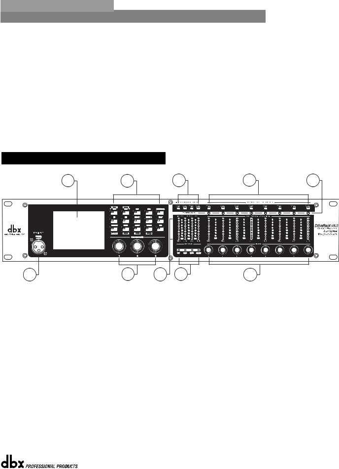
1.2 - Front Panel (4800)
1 |
2 |
3 |
4 |
5 |
6 7 8 9 10
1. LCD Display
The color 1/4 VGA (320x240) display provides viewing of all parameters and attributes of the DriveRack 4800.
2. Function Buttons
The Function buttons of the DriveRack 4800 allow direct access to all editing and navigating functions of the DriveRack 4800. The functions of the aforementioned buttons are as follows:
PREV is used to navigate back through the various pages of any module. Pressing and holding the PREV button allows you to enter Copy/Paste Mode, where subsequent presses of PREV allow copying all the function DSP parameters.
NEXT is used to navigate forward through the various pages of any module. Pressing and holding the NEXT button allows you to enter Copy/Paste Mode, where subsequent presses of NEXT allow pasting of all the function DSP parameters.
EQ 1 is used to select and/or enter the first Input EQ module or the Output EQ module.
EQ 2 is used to select and/or enter the second Input EQ module or the Output EQ module.
BANDPASS is used to select and/or enter the Bandpass/Crossover function.
®
DriveRack® 4800/4820 User Manual |
3 |
|
|

Section 1 |
Getting Started |
DriveRack® |
OUTPUT is used to select and/or enter the Input and Output setup module.
ROUTE/MIX is used to select and/or enter either the Input or Output Router or Mixer module.
INSERT 1 is used to select and/or enter the first Insert function in either the Input or Output.
INSERT 2 is used to select and/or enter the second Insert function in either the Input or Output.
DELAY is used to select and/or enter either the Input or Output Delay module.
PRESET is used to return to the Preset Screen and exit out of any mode. Pressing and holding PRESET enters Preset Recall Mode allowing selection of an alternate preset.
STORE is used to store any preset changes. Pressing and holding STORE lets you Delete a preset from the preset table.
UTILITY is used to access the Utility menu. Pressing and holding UTILITY allows access to the Meter Mode where additional metering is available.
WIZARD is used to enter the Wizard section. Pressing and holding the WIZARD button enters Configuration Mode where changes to the preset configuration can be made.
RTA is used to view the Real Time Analyzer. In other modes (such as Preset Recall or Configuration) pressing and holding the RTA button is used to Load those changes.
3. Input Channel Select A-D
These buttons are used to select the desired input channel.
4. Ouput Channel Select 1-8
These buttons are used to select the desired output channel.
5.Threshold Meters
The tri-color Threshold meters indicate that the threshold level has been exceeded in the Output Insert Limiter, Compressor or Auto Gain Control.
6. RTA Input Jack
This balanced XLR input is used for the connection of an RTA microphone, which may be used with the Auto EQ Wizard and RTA functions. 48V phantom power is always engaged on this connector.
7. Parameter Control 1-3
These three knobs are used to select and edit parameters.
8. Input Meters
The DriveRack 4800 provides you with four independent eight segment input headroom meters that range from SIG (-48dB) to 0dB. These meters monitor the signal directly following the input section.
®
4 |
DriveRack® 4800/4820 User Manual |
|
|
DriveRack® |
Getting Started |
Section 1 |
9. Status LEDs
This cluster of four LEDs indicate the following functions:
CLIP - indicates either A/D, D/A, or DSP clipping.
SYNC - indicates DSP syncing to an internal clock, AES/EBU, CobraNet, or Wordclock input.
RS-232 - indicates PC connection via RS-232.
LINK/ACT - indicates connection to and/or activity on an Ethernet network.
10. Output Adjustment/Mute Knobs 1-8
The Output Trim/Mute knobs provide Trim Gain adjustment of each output. Pressing the knob mutes that output.
11. Output Meters
The DriveRack 4800 provides eight independent eight segment output headroom meters that range from SIG (-48dB) to 0dB.
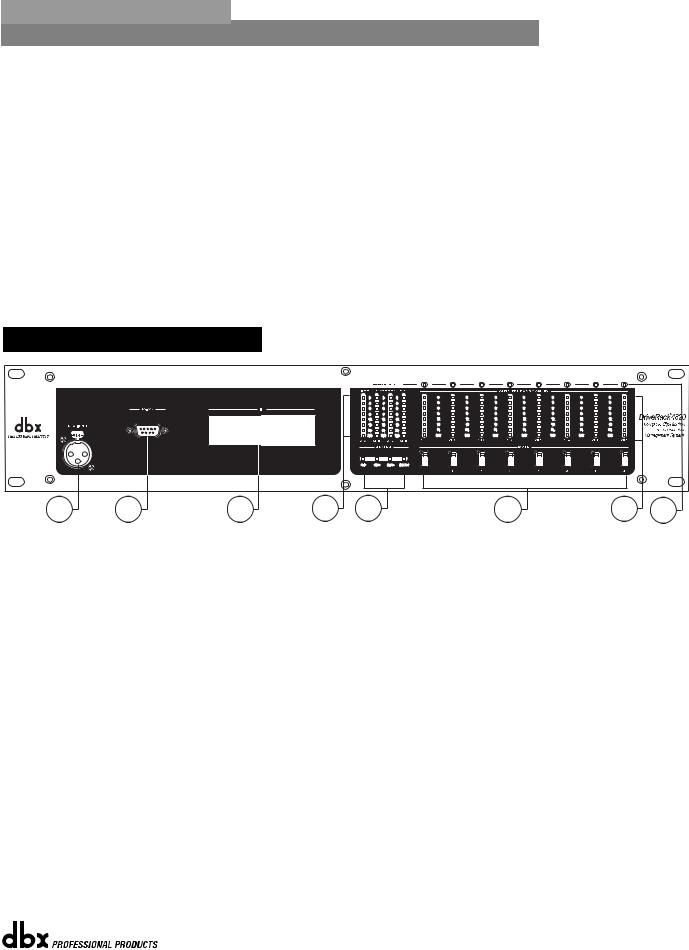
1.3 - Front Panel (4820)
1 |
2 |
3 |
4 |
5 |
6 |
7 |
8 |
1. RTA Input Jack
This balanced XLR input is used for the connection of an RTA microphone, which may be used with the Auto EQ function in the Wizard. 48V phantom power is always engaged on this connector.
2. Serial PC Connection (DB-9)
This DB-9 connection is used to communicate to the System Architect control software and uses RS232 protocol. This connection requires a Null Modem cable and one is included with the unit.
3.Alpha Numeric Display
This display shows the ID# of the DriveRack 4820 unit. It can also show various error codes.
4. Input Meters
The DriveRack 4820 provides four independent eight segment input headroom meters that range from SIG (-48dB) to 0dB. These meters monitor the signal directly following the input section.
5. Status LEDs
This cluster of four LEDs indicate the following functions:
®
DriveRack® 4800/4820 User Manual |
5 |
|
|

Section 1 |
Getting Started |
DriveRack® |
CLIP - indicates either A/D, D/A, or DSP clipping.
SYNC - indicates DSP syncing to an internal clock, AES/EBU or Wordclock input. RS-232 - indicates PC connection via RS-232.
LINK/ACT - indicates connection to and/or activity on an Ethernet network.
6. Mute Buttons
The DriveRack 4820 provides a MUTE button for each output.
7. Output Meters
The DriveRack 4800 provides eight independent eight-segment output headroom meters that range from SIG (-48dB) to 0dB.
8.Threshold Meters
The tri-color Threshold meters indicate that the threshold level has been exceeded in the Output Insert Gate, Limiter, Compressor or Auto Gain Control.
1. 4 - System Architect Control Software
The System Architect software provides control and monitoring of the DriveRack 4800 and 4820 devices. Multiple units can be networked and controlled together along with other products from Harman Professional. It is the only software package that allows complete control of all the links in the signal chain from within a single application. It enables flagship products from best-in-class brands to act as one collective consciousness, and makes real the benefits only a truly unified system can bring.
Understanding the System Architect software is the key to getting full functionality from the DriveRack 4800 and 4820 products.
System Architect Features
•Supports Ethernet control
•Supports Serial control
•Supports CobraNet audio
•Supports up to 64 channels of streaming audio
•Supports sample rates up to 96kHz
•Supports up to 65,536 HiQnet nodes in a single system
•Wireless 802.11g compatible
•Optimized for tablet PC use
•Optimized for remote access
•Universal Plug and Play compliant
•Multiple computer support
The DriveRack 4800/4820 are compatible with the following products via System Architect
•AKG WMS 4000 wireless microphone system
•BSS Soundweb London networked audio distribution system
•Crown I-Tech tour sound amplifier range
•Crown amplifier PIP modules - Lite, USP3, USP3/CN
•JBL DP Series intelligent networked amplified speaker
•Studer Vista 8 digital production console
®
6 |
DriveRack® 4800/4820 User Manual |
|
|

DriveRack® |
Getting Started |
Section 1 |
Minimum System Requirements for System Architect are:
1GHz, Pentium III processor 512MB RAM
Windows 2000 or XP service pack 2
Recommended System Requirements:
3GHz, Pentium 4 processor 1GB RAM
Recommended screen resolution: 1024 x 768 pixels or higher
Installation
•Install the System Architect GUI software from either the Harman Professional website at www.harmanpro.com or from the dbx website at www.dbxpro.com or from the included CD ROM onto your computer.
•Once the software setup is downloaded, double click on the file named: System Architect setup.
•The application will proceed to prompt you for the installation location.
•Once the software installation has been completed, it is recommended that you restart your computer.
Note
You must disable virus protection software during the installation of the System Architect software.
®
DriveRack® 4800/4820 User Manual |
7 |
|
|

Section 1 |
Getting Started |
DriveRack® |
®
8 |
DriveRack® 4800/4820 User Manual |
|
|

DriveRack® |
Section 2 |
|
DriveRack Philosophy |
|
PRESETS |
|
ATTRIBUTES |
®

Section 2 |
DriveRack Philosophy |
DriveRack® |
2.1 - DriveRack 4800/4820 Philosophy
The philosophy of the DriveRack 4800 and 4820 revolves around the concept of two elements: Attributes and Presets.
Attributes
Attributes are parameters that are global like sample rate, analog I/O gain structure, or RTA microphone preamp gain. Most Attributes are found in the Utility menus. Depending on the function, Attributes are either stored instantly as they are changed or upon exiting the Utility menus, and are stored instantly as they are changed.
Presets
A Preset is the name given to the audio processing and routing that is occurring in the DriveRack 4800 or 4820. Up to 50 Presets can be stored in the DriveRack 4800 or 4820. The Preset can be further broken down into two parts: the signal path (or Configuration) and the actual Parameters (listed below) found in the individual processing functions or modules. Presets are stored manually in the DriveRack unit by either using the STORE button on the front panel of the 4800 or by using the Preset Tool in the System Architect software. Presets for the DriveRack 4800 or 4820 can also be saved on the PC as a preset file.
Configuration
The DriveRack 4800 and 4820 units offer two types of processing modules. The first type includes functions like EQ, Bandpass Filters, Mixers, Routers, and Delay; these functions can be linked together but are fixed in their positions. The second type includes insertable functions that can be selected from a list in four positions; this list includes Feedback Suppression, Compression, Noise Gate, Limiter, Notch Filter, Auto Gain Control, AutoWarmth, etc. The process of linking modules and selecting inserts is called Configuring. The 4800 and 4820 can be configured with hundreds of different signal routing and processing variations.
Parameters
Parameters refers to the processing function parameters. Control of any parameter can be done via the front panel interface of the DriveRack 4800 with its Function and Channel buttons, or the System Architect software. Some parameters, such as output gain, can be adjusted from a ZC series wall panel controller.
System Architect Software / DriveRack Plug-In
The HiQnet System Architect Graphic User Interface application (referred to hereafter as System Architect or GUI) is the control software for the DriveRack 4800 and 4820. In addition to parameter adjustment and all the same control as the front panel of the 4800, System Architect provides the ability to control multiple units. The GUI can save and recall Preset files as well as a Device file that includes all the Presets and Attributes in the unit. Besides these files types, it can also store a venue file with all the units in the network. It can provide a wealth of additional utility like wireless control, grouping functions, custom control panels and more; see Software Operation in Section 4.
®
10 |
DriveRack® 4800/4820 User Manual |
|
|
DriveRack® |
Section 3 |
|
Front Panel Operation |
|
NAVIGATION |
|
MODES |
®

Section 3 |
Front Panel Operation |
DriveRack® |
The DriveRack 4800 is modal in its operation with different types of navigation depending on the mode that the unit is in. For each of the modes, navigation has been optimized to ensure speed and accuracy.
3.1 - Navigation
The DriveRack 4800 uses three types of navigation to access system attributes and parameters, Matrix navigation, Scroll navigation, and Page navigation. Some functions require the use of more than one type of navigation; an example of this is the Edit mode, where a combination of Matrix navigation and Page navigation are used to access individual parameters in the various processing modules.
Matrix Navigation - This refers to moving around the matrix, field, or grid of processing modules that are shown on the main preset screen. Matrix navigation relies on the use of the channel and Function buttons to find the desired processing module. For example, if you were in Copy/Paste mode (see Copy/Paste below) and wanted to copy the parameters of the Input Graphic EQ on Input B, you would simply press the INPUT B button then the EQ1 button, and the Input Graphic EQ on input B would be highlighted.
®
12 |
DriveRack® 4800/4820 User Manual |
|
|

DriveRack® |
Front Panel Operation |
Section 3 |
Scroll Navigation - This navigation is used in the Utility menus, as well as in storing, recalling and deleting presets. It is very useful for finding menu offerings that are located within another sub-menu. For example, the RTA mic pre gain is located within the Gain/Trim sub-menu of the Utility.
Page Navigation - This is the easiest and most common type of navigation within the DriveRack 4800. Page navigation is used when there are several pages of parameters that need to be accessed. An example of Page navigation is found in the Compressor editor where there are three pages of parameters and the NEXT and PREV PAGE buttons are used to move between these pages.
3.2 - Modes of Operation
The standard mode of operation of the DriveRack 4800 is Edit Preset (or Edit) mode. This mode is the gateway to all editing and is the only “location” from which all the other modes can be accessed. This mode can be returned to from any other mode or menu by pressing the PRESET button. Pressing the PRESET button returns you to the main preset screen that shows the signal path through the unit and all the current processing functions. Additionally, this main preset screen in Edit mode is the safe or home page; all changes to the system (editing, recalling, storing, deleting, etc.) require button presses to access these menus. The DriveRack 4800 defaults to this screen and mode upon startup, and returns to this mode when exiting from all the other modes and menus including: Recall Preset, Store Preset, Delete Preset, Copy/Paste, Utility, Meter, Wizard, and Configuration. These other modes and/or menus are indicated by either a button with normal text (White on Black), or by a button with reversed text (Black on White). The function in normal text is the standard mode, accessed by pressing the button, while the function in reversed text is the alternate mode, and is accessed by pressing and holding the button for more than two seconds. An example of this is the STORE/DELETE button, where Store Preset is the standard mode that is found by pressing the button, and Delete Preset is the alternate mode that is accessed by pressing and holding for more than two seconds.
®
DriveRack® 4800/4820 User Manual |
13 |
|
|

Section 3 |
Front Panel Operation |
DriveRack® |
Edit Preset Mode - In Edit mode, access to any of the processing functions is no more than two button presses away.
1.Return to Edit mode by pressing the PRESET button.
2.To select the input or output channel that you would like to edit, press the INPUT or OUTPUT button that corresponds with that channel.
3.Once you have selected the desired channel, press the desired function button from the processing button field.
4.Now that you have reached the desired processing function, you can use the PREV or NEXT buttons to navigate through the pages of parameters available and then use the Encoder Knobs below the buttons to adjust the value.
Copy/Paste Mode - Copy/Paste mode lets you navigate through the processing matrix and select modules to copy and paste. It is only available from the preset main screen since it is an adjunct to the Edit mode, but it is very useful when editing presets. Obviously you can only copy and paste between like modules. (i.e. Graphic EQ to Graphic EQ, etc.)
1.Press the PRESET button to return to the main preset screen (showing the signal path and processing functions).
2.To enter Copy/Paste mode, press and hold either the PREV/COPY or NEXT/PASTE buttons.
3.Navigate to the processing function that you want to copy by pressing the desired Channel and Function buttons.
4.Once at the function, press the PREV/COPY button to copy the parameters.
®
14 |
DriveRack® 4800/4820 User Manual |
|
|

DriveRack® |
Front Panel Operation |
Section 3 |
5.Navigate to the location where you want to paste and press the NEXT/PASTE button.
6.To exit Copy/Paste mode and return to Edit mode, press the PRESET button.
Recall Preset Mode - Any preset in the preset list can be recalled, as long as it is within the Preset Minimum and Maximum range set in the Utility menu. For more information on Preset Min/Max, see Utilities in Section 7.
1. While in Edit mode press and hold the PRESET/RECALL button for two seconds.
2.Select the preset you would like to recall.
3.Press the RTA/LOAD button to recall the preset.
4.To exit Recall mode and return to Edit mode, without recalling a preset, press the PRESET button.
Store Preset Mode - Once a preset has been edited it can be stored by pressing the STORE button. The DriveRack 4800 can store up to 50 Presets.
1. While in Edit mode press the STORE button.
2.To store the preset with the same name and in the same location press STORE again, and then one more time to confirm storing of this preset.
3.To change the name, press Encoder Knob #2, then use Encoder Knobs #1 and #2 to change the character and the cursor position. Once the desired name is created press the STORE button.
4.To store to a new location in the preset table turn Encoder Knob #1.
5.Once the name or location has been changed, press the STORE button to store the preset, then once more to confirm storing this preset.
6.To exit Store mode and return to Edit mode without storing the preset, press the PRESET button.
Delete Preset Mode - Any preset in the preset list can be deleted.
WARNING: At least one preset must remain stored at all times, or there will be no preset to start with when creating other presets. DO NOT DELETE ALL PRESETS!
®
DriveRack® 4800/4820 User Manual |
15 |
|
|

Section 3 |
Front Panel Operation |
DriveRack® |
1. While in Edit mode, press and hold the STORE/DELETE button for two seconds.
2.Select the preset you would like to delete.
3.Press the STORE/DELETE button to delete the preset, and once more to confirm the deletion.
4.To exit Delete and return to Edit mode without deleting the preset, press the PRESET button.
Utility Menu - Many of the global attributes of the DriveRack 4800 are located in the Utility menus, including Sample Rate, Analog I/O Gain Structure, etc.
1. While in Edit mode press the UTILITY/METER button.
2.Scroll through the various Utility menus using Encoder Knob #1. Press the knob to enter the desired menu.
3.Once in a Utility menu, use the PREV and NEXT buttons to navigate through the pages within that menu.
4.To exit the Utility menus and return to Edit mode, press the PRESET button.
Meter Menu - The Meter menu provides you with additional high resolution meters for all the dynamics functions of the DriveRack 4800.
1. While in Edit mode press and hold the UTILITY/METER button.
®
16 |
DriveRack® 4800/4820 User Manual |
|
|

DriveRack® |
Front Panel Operation |
Section 3 |
2.Use the PREV and NEXT buttons to navigate through the pages of meters.
3.To exit Meter menus and return to Edit mode, press the PRESET button.
Wizard Mode - The Wizard mode will provide you with setup functions. The Wizard mode is not functional in v1.00.
1. While in Edit mode press the WIZARD/CONFIG button.
2.Use the PREV and NEXT buttons to navigate through the Wizard pages.
3.To exit the Wizard and return to Edit mode without making any changes, press the PRESET button.
Configuration Mode - The DriveRack 4800 is configurable from the front panel through the Configuration mode. This mode lets you create a signal path and a combination of processing functions.
1. While in Edit mode press and hold the WIZARD/CONFIG button for two seconds.
2.Use the CHANNEL and FUNCTION buttons to navigate around the processing matrix.
3.In positions where a change of processing is possible, turning the Encoder #1 knob will accomplish this change.
4.To link adjacent like functions, turn Encoder #3 knob.
®
DriveRack® 4800/4820 User Manual |
17 |
|
|

Section 3 |
Front Panel Operation |
DriveRack® |
5.Once the desired configuration is created, press and hold the RTA/LOAD button to load the configuration.
6.To exit Configuration and return to Edit mode without making any changes to the configuration, press the PRESET button.
®
18 |
DriveRack® 4800/4820 User Manual |
|
|

DriveRack® |
Section 4 |
|
Software Operation |
|
MODULE VIEW |
|
DEVICE VIEW |
|
VENUE VIEW |
®
 Loading...