


MODEL 166XL
C O M P R E S S O R G AT E
®
 A Harman International Company

C A U T I O N |
RIS K O F ELECTRI C SHOCK |
D O NO T OPEN |
ATTENTION: RISQU E D E CHO C ELECTRIQU E - N E PA S OUVRIR |
WARNING: T O REDUC E TH E RIS K O F FIR E O R ELECTRIC SHOC K D O NO T EXPOS E THI S EQUIPMEN T T O RAI N O R MOISTURE
The symbols shown above are internationally accepted symbols that warn of potential hazards with electrical products. The lightning flash with arrowpoint in an equilateral triangle means that there are dangerous voltages present within the unit. The exclamation point in an equilateral triangle indicates that it is necessary for the user to refer to the owner’s manual.
These symbols warn that there are no user serviceable parts inside the unit. Do not open the unit. Do not attempt to service the unit yourself. Refer all servicing to qualified personnel. Opening the chassis for any reason will void the manufacturer’s warranty. Do not get the unit wet. If liquid is spilled on the unit, shut it off immediately and take it to a dealer for service. Disconnect the unit during storms to prevent damage.
U.K. MAINS PLUG WARNING
A moulded mains plug that has been cut off from the cord is unsafe. Discard the mains plug at a suitable disposal facility. NEVER UNDER ANY CIRCUM-
STANCES SHOULD YOU INSERT A DAMAGED OR CUT MAINS PLUG INTO A 13 AMP POWER SOCKET. Do not use the mains plug without the fuse cover in place. Replacement fuse covers can be obtained from your local retailer.
Replacement fuses are 13 amps and MUST be ASTA approved to BS1362.
WARNING
FOR YOUR PROTECTION, PLEASE READ THE FOLLOWING:
WATER AND MOISTURE: Appliance should not be used near water (e.g. near a bathtub, washbowl, kitchen sink, laundry tub, in a wet basement, or near a swimming pool, etc). Care should be taken so that objects do not fall and liquids are not spilled into the enclosure through openings.
POWER SOURCES: The appliance should be connected to a power supply only of the type described in the operating instructions or as marked on the appliance. GROUNDING OR POLARIZATION: Precautions should be taken so that the grounding or polarization means of an appliance is not defeated.
POWER CORD PROTECTION: Power supply cords should be routed so that they are not likely to be walked on or pinched by items placed upon or against them, paying particular attention to cords at plugs, convenience receptacles, and the point where they exit from the appliance.
SERVICING: To reduce the risk of fire or electric shock, the user should not attempt to service the appliance beyond that described in the operating instructions. All other servicing should be referred to qualified service personnel.
FOR UNITS EQUIPPED WITH EXTERNALLY ACCESSIBLE FUSE RECEPTACLE:
Replace fuse with same type and rating only.
MULTIPLE-INPUT VOLTAGE: This equipment may require the use of a different line cord, attachment plug, or both, depending on the available power source at installation. Connect this equipment only to the power source indicated on the equipment rear panel. To reduce the risk of fire or electric shock, refer servicing to qualified service personnel or equivalent.
ELECTROMAGNETIC COMPATIBILITY
This unit conforms to the Product Specifications noted on the Declaration of Conformity. Operation is subject to the following two conditions:
•this device may not cause harmful interference, and
•this device must accept any interference received, including interference that may cause undesired operation.
Operation of this unit within significant electromagnetic fields should be avoided.
• use only shielded interconnecting cables.
SAFETY INSTRUCTIONS
NOTICE FOR CUSTOMERS IF YOUR UNIT IS EQUIPPED WITH A POWER CORD.
WARNING: THIS APPLIANCE MUST BE EARTHED.
The cores in the mains lead are coloured in accordance with the following code:
GREEN and YELLOW - Earth BLUE - Neutral BROWN - Live
As colours of the cores in the mains lead of this appliance may not correspond with the coloured markings identifying the terminals in your plug, proceed as follows:
•The core which is coloured green and yellow must be connected to the terminal in the plug marked with the letter E, or with the earth symbol, or coloured green, or green and yellow.
•The core which is coloured blue must be connected to the terminal marked N or coloured black.
•The core which is coloured brown must be connected to the terminal marked L or coloured red.
This equipment may require the use of a different line cord, attachment plug, or both, depending on the available power source at installation. If the attachment plug needs to be changed, refer servicing to qualified service personnel who should refer to the table below. The green/yellow wire shall be connected directly to the unit's chassis.
|
|
|
CONDUCTOR |
WIRE COLOR |
||||||
|
|
|
|
|
||||||
Normal |
Alt |
|||||||||
|
|
|
|
|
|
|
|
|||
|
|
|
|
|
|
|
|
|
|
|
|
|
L |
LIVE |
BROWN |
BLACK |
|||||
|
N |
NEUTRAL |
BLUE |
WHITE |
||||||
|
|
|
|
|
|
|
|
|
|
|
|
|
E |
|
|
EARTH GND |
GREEN/YEL |
GREEN |
|||
|
|
|
|
|
||||||
WARNING: If the ground is defeated, certain fault conditions in the unit or in the system to which it is connected can result in full line voltage between chassis and earth ground. Severe injury or death can then result if the chassis and earth ground are touched simultaneously.
DECLARATION OF CONFORMITY
Manufacturer’s Name: |
dbx Professional Products |
Manufacturer’s Address: |
8760 S. Sandy Parkway |
|
Sandy, Utah 84070, USA |
declares that the product: |
|
dbx 166XL
conforms to the following Product Specifications:
Safety: EN 60065 (1993)
IEC65 (1985) with Amendments 1, 2, 3
EMC: EN 55013 (1990)
EN 55020 (1991)
Supplementary Information:
The product herewith complies with the requirements of the Low Voltage Directive 73/23/EEC and the EMC Directive 89/336/EEC as amended by Directive 93/68/EEC.
dbx Professional Products Vice-President of Engineering 8760 S. Sandy Parkway Sandy, Utah 84070, USA
June 3, 1998
European Contact: Your Local dbx Sales and Service Office or International Sales Office
68 Sheila Lane Valparaiso, Indiana 46383, USA
Tel: (219) 462-0938
Fax: (219) 462-4596

dbx 166XL COMPRESSOR / GATE
MANUAL CONTENTS
English
INTRODUCTION . . . . . . . . . . . . . . . . . . . . . . . . . . . . . . . . . . . . . . . . . . . . . . . . . . . . . . 2
INSPECTION . . . . . . . . . . . . . . . . . . . . . . . . . . . . . . . . . . . . . . . . . . . . . . . . . . . . . . . . . 2
OPERATING CONTROLS . . . . . . . . . . . . . . . . . . . . . . . . . . . . . . . . . . . . . . . . . . . . . . . . 2
OPERATING NOTES . . . . . . . . . . . . . . . . . . . . . . . . . . . . . . . . . . . . . . . . . . . . . . . . . . . 6
CONNECTING THE 166XL TO YOUR SYSTEM . . . . . . . . . . . . . . . . . . . . . . . . . . . . . . . . 10
INSTALLATION CONSIDERATIONS . . . . . . . . . . . . . . . . . . . . . . . . . . . . . . . . . . . . . . . . . 12
TECHNICAL SUPPORT / FACTORY SERVICE . . . . . . . . . . . . . . . . . . . . . . . . . . . . . . . . . . 12
Français
INTRODUCTION . . . . . . . . . . . . . . . . . . . . . . . . . . . . . . . . . . . . . . . . . . . . . . . . . . . . . . 13
VÉRIFICATION . . . . . . . . . . . . . . . . . . . . . . . . . . . . . . . . . . . . . . . . . . . . . . . . . . . . . . . 14
COMMANDES . . . . . . . . . . . . . . . . . . . . . . . . . . . . . . . . . . . . . . . . . . . . . . . . . . . . . . . 14
NOTES D'UTILISATION . . . . . . . . . . . . . . . . . . . . . . . . . . . . . . . . . . . . . . . . . . . . . . . . 18
RACCORDEMENT DU 166XL AU SYSTEME DE SONORISATION . . . . . . . . . . . . . . . . . . . 22
NOTES SUR L'INSTALLATION . . . . . . . . . . . . . . . . . . . . . . . . . . . . . . . . . . . . . . . . . . . . 24
ASSISTANCE TECHNIQUE ET SERVICE USINE . . . . . . . . . . . . . . . . . . . . . . . . . . . . . . . . 25
Deutsch
EINLEITUNG . . . . . . . . . . . . . . . . . . . . . . . . . . . . . . . . . . . . . . . . . . . . . . . . . . . . . . . . 26
KONTROLLE . . . . . . . . . . . . . . . . . . . . . . . . . . . . . . . . . . . . . . . . . . . . . . . . . . . . . . . . 26
BEDIENUNGSELEMENTE . . . . . . . . . . . . . . . . . . . . . . . . . . . . . . . . . . . . . . . . . . . . . . . . 27
BEDIENUNGSHINWEISE . . . . . . . . . . . . . . . . . . . . . . . . . . . . . . . . . . . . . . . . . . . . . . . . 30
ANSCHLIEßEN DES DBX 166XL AN IHRE ANLAGE . . . . . . . . . . . . . . . . . . . . . . . . . . . . 35
ANSCHLUßHINWEISE . . . . . . . . . . . . . . . . . . . . . . . . . . . . . . . . . . . . . . . . . . . . . . . . . . 37
SERVICE UND KUNDENDIENST . . . . . . . . . . . . . . . . . . . . . . . . . . . . . . . . . . . . . . . . . . . 38
Español
INTRODUCCION . . . . . . . . . . . . . . . . . . . . . . . . . . . . . . . . . . . . . . . . . . . . . . . . . . . . . . 39
INSPECCION . . . . . . . . . . . . . . . . . . . . . . . . . . . . . . . . . . . . . . . . . . . . . . . . . . . . . . . . . 39
CONTROLES OPERATIVOS . . . . . . . . . . . . . . . . . . . . . . . . . . . . . . . . . . . . . . . . . . . . . . 40
NOTAS PARA EL OPERADOR . . . . . . . . . . . . . . . . . . . . . . . . . . . . . . . . . . . . . . . . . . . . 44
CONEXION DEL 166XL AL SISTEMA DE SONIDO . . . . . . . . . . . . . . . . . . . . . . . . . . . . . 49
CONSIDERACIONES PARA LA INSTALACION . . . . . . . . . . . . . . . . . . . . . . . . . . . . . . . . . 51
ASISTENCIA TÉCNICA / SERVICIO DE FABRICA . . . . . . . . . . . . . . . . . . . . . . . . . . . . . . . 52
Specifications . . . . . . . . . . . . . . . . . . . . . . . . . . . . . . . . . . . . . . . . . . . . . . . . . . . . . . . 54
dbx 166XL COMPRESSOR / GATE |
PROFESSIONAL PRODUCTS |
|
® |
|
|
INTRODUCTION
Congratulations on choosing the dbx 166XL Compressor / Gate. The 166XL provides two channels of noise gating, OverEasy® or classic hard knee compression and PeakStop® limiting to give complete control of signal dynamics to studios, sound reinforcement companies, musicians, or anyone who needs quality processing quickly and easily. We recommend that you take a moment and read through the manual as it provides information that will assist you in using your unit to its fullest potential. Features Include:
•Stereo or Dual Mono operation of gating, compression and peak limiting.
•OverEasy®/Hard Knee Selection - allows selection between our famous OverEasy compression curve and the classic “Hard Knee” curve popularized by the original dbx 160, 161 and 162.
•Expander/Gate Circuit - with variable release time and +15dBu maximum threshold.
•Selectable Low Frequency Shelf (via Contour button) in the Sidechain Path - recommended when compressing mixed program material to prevent low frequency energy from “punching holes” in the sound.
•PeakStop® Limiting - provides control of maximum peak levels at the output of the 166XL regardless of any other control. PeakStop comes after the compression, gating and other circuitry including the output gain, so it sets an absolute limit for peak excursions before they reach the output.
•True RMS Level Detection - senses the power in the program in a musical manner, much as human hearing does, giving results superior to peak or average detection.
•Hardwire System Bypass Buttons on both channels - allow the audio to pass even if the unit is unplugged, and are also useful for comparing the processed and unprocessed signals.
•10-Segment LED Display for GAIN REDUCTION (up to 30dB).
•Electronically Balanced XLR and 1/4” TRS Input and Output Jacks
•Separate Sidechain Inserts - enables an outboard processor or signal to control compression or gating.
•DC-Controlled Parameters - the signal does not pass thru any of the parameter controls. Instead a DC voltage controls all functions; this eliminates any possibility of potentiometer noise developing over time.
INSPECTION
Verify that the 166XL package contains the following:
•166XL Unit
•AC Power Cord
•Operation Manual
•Registration Card
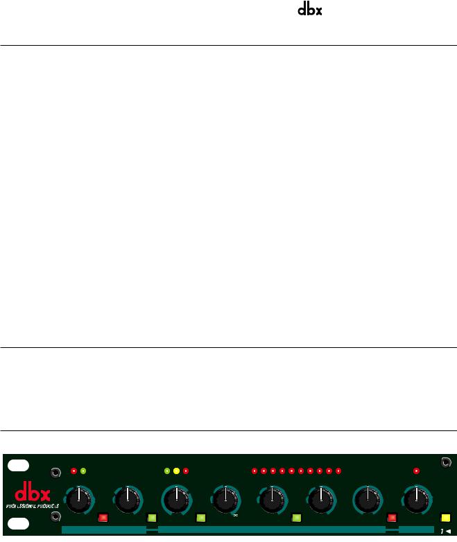
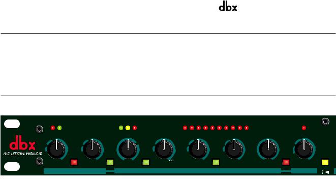
OPERATING CONTROLS
Front Panel
GAIN REDUCTION (dB)
BELOW ABOVE |
BELOW ABOVE |
30 25 20 15 12 10 8 6 4 2 |
ABOVE |
CHANNEL ONE
|
-25 |
|
|
-20 |
-10 |
0 |
2:1 |
|
|
|
|
|
|
0 |
|
|
|
+10 |
|
-45 |
|
-10 |
|
|
1.3:1 |
4:1 |
|
|
|
|
-10 |
|
|
+10 |
+5 |
+15 |
-45 |
||
|
|
-30 |
|
|
+10 |
|
|
|
|
|
|
|
|||||||
|
|
|
|
|
|
|
|
|
|
|
|
|
|
|
|
|
Stereo |
||
|
|
SC Enable |
|
Contour |
|
|
OverEasy |
|
|
|
Auto |
|
|
|
|
Bypass |
|
Couple |
|
OFF |
dBu +15 |
Fast |
Slow |
-40 |
dBu |
+20 |
1:1 |
:1 |
Fast |
Slow |
Fast |
Slow |
-20 |
dB |
+20 |
|
0 |
dBu +20 |
|
THRESHOLD |
RELEASE |
THRESHOLD |
RATIO |
|
ATTACK |
RELEASE |
OUTPUT GAIN |
|
PEAKSTOP |
MASTER |
|||||||||
|
EXPANDER/GATE |
|
|
|
|
|
|
COMPRESSOR |
|
|
|
|
|
|
LIMITER |
||||
|
|
|
|
|
|
|
|
|
|
|
|
|
|
||||||
EXPANDER/GATE Section
Expander/Gate THRESHOLD Control and LEDs (BELOW/ABOVE):
Adjusting this control sets the level at which the gate will open and allow the signal at the input to pass through to the output. Turning the knob fully counterclockwise (to OFF) allows the gate to pass signals unattenuated, effectively bypassing the gate. Turning the knob fully clockwise causes the gate to attenuate input signals below +15dBu.
The two Expander/Gate LEDs indicate the relationship of the input signal level to the threshold setting. The red LED lights when the signal is BELOW threshold, the green LED lights when the signal is ABOVE threshold.
Note: The 166XL’s expander/gate attack rate (which controls how fast the signal is restored after being attenuated) is internally set to be very fast - fast enough to allow all of the transient at the beginning of a note, vocal or spoken word to come through.

dbx 166XL COMPRESSOR / GATE
Note: The 166XL’s expansion ratio is internally fixed, at approximately 10:1. This ratio helps to eliminate the artifacts normally associated with common switch gates. Attenuation is >50dB.
SIDECHAIN (SC) ENABLE Switch and LED:
This switch enables the 1/4” TRS connector of the sidechain, allowing external processing of the detector signal. It has no effect if there is nothing plugged into the sidechain loop; however the switch will still light indicating the sidechain is enabled.
Expander/Gate RELEASE Control:
This control determines the rate at which the gate closes once the signal at the INPUT or SIDECHAIN INSERT falls below the threshold. SLOW settings are useful for gating out noise present behind vocals and acoustic instruments. FAST settings are useful for tightening up the sound of percussion (e.g., kick or snare drum) and drying up leakage from other instruments into percussion tracks.
Note: The gate release rate is “accelerating” in that the dB/Sec rate continually increases as the gate closes.
CONTOUR Button and LED:
Depress this button to make the 166XL’s detection circuitry less sensitive to low frequency energy, preventing this energy from “punching holes” in the sound, especially with mixed program. With the CONTOUR button Out, the 166XL’s detector is frequency-independent. The CONTOUR LED turns On when the CONTOUR button is depressed.
COMPRESSOR Section
GAIN REDUCTION Meter:
This meter displays how much the signal is being attenuated by the compressor and the gate.
Compressor THRESHOLD LEDs:
These three LEDs indicate the relationship of the input signal level to the threshold of compression. The green BELOW LED is On when the signal is below threshold and the red ABOVE LED is On when the signal is above threshold. When the 166XL is switched to OverEasy mode, the yellow LED is On when the signal is in the OverEasy region (See Figure 2).
Note: Even though no input signal is being applied, it is normal for the LEDs to flicker when the power is applied or removed.
Compressor THRESHOLD Control:
Adjust this knob to set the threshold of compression from -40dBu (7.8mVrms) to +20dBu (7.8Vrms). Setting the Compressor THRESHOLD control to +20dB will prevent all but the highest level peaks from being compressed. (Setting the Compressor RATIO to 1:1 will turn the Compressor off, regardless of the setting of the Compressor THRESHOLD control.)
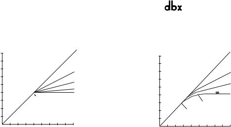
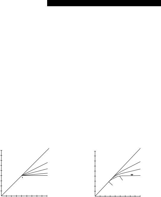
In Hard Knee mode (OVEREASY button out), the THRESHOLD sets a reference level above which input signals will be processed by the 166XL’s gain change circuitry in the manner defined by the setting of the RATIO control. Input signals which fall below this level will pass through the 166XL unprocessed (except for fixed gain changes directed by the OUTPUT GAIN control). See Figure 1.
In OverEasy mode (OVEREASY button depressed), signals begin to gradually activate the 166XL’s gain change circuitry as they approach the THRESHOLD reference level and they do not get fully processed in the manner defined by the RATIO control until they have passed somewhat above the THRESHOLD reference level. In OverEasy mode there is no distinct point at which processing begins, and the THRESHOLD setting corresponds to a point on the input/output transfer curve midway between the onset of processing and that point at which the transfer curve corresponds to the setting of the RATIO control. Figure 2 shows the OverEasy compression curves and how they correlate with the THRESHOLD LEDs.
OVEREASY Button and LED:
Depress this button to select the OverEasy® compression characteristic. The yellow THRESHOLD LED turns On when the signal is in the OverEasy region. When this button is in the Out position, the 166XL operates as a hard knee compressor/limiter. (Yellow OverEasy LED is active only in OverEasy Mode.)
In Hard Knee mode, the threshold of compression is defined as that point above which the output level no longer changes on a 1:1 basis with changes in the input level. See Figure 1.
In OverEasy mode, the threshold of compression is defined as the middle of the OverEasy threshold region, that is, “half-way” into compression, as shown in Figure 2.
dbx 166XL COMPRESSOR / GATE |
PROFESSIONAL PRODUCTS |
|
® |
|
|
Compressor RATIO Control:
Rotate this control clockwise to increase the amount of compression from 1:1 (no compression) up to °:1 (no increase in output level, regardless of input level increases above threshold.)
OUTPUT LEVEL (dB)
+20
+15
+10
+5
0
-5
-10
-15
1:1 Unity
RED
Above Threshold
2:1
4:1
20:1
 :1
:1
Rotation Point Threshold
GREEN
Below Threshold
OUTPUT LEVEL (dB)
+20
+15
+10
+5
0
−5
−10
−15
|
|
|
|
|
1:1 |
|
|
|
|
|
2:1 |
|
|
|
|
|
4:1 |
|
|
|
|
|
:1 |
|
|
|
|
R |
RED |
|
|
|
|
|
|
|
|
|
YELLOWA |
|
|
|
|
|
BE |
Above Threshold |
|
|
|
|
M |
|
|
|
RE |
E |
N |
OverEasy Range |
|
|
|
|
|
||
G |
|
|
|
|
|
|
|
|
|
|
|
Below Threshold
-15 -10 -5 0 +5 +10 +15 +20 |
−15 −10 −5 0 +5 +10 +15 +20 |
|
|
INPUT LEVEL (dB) |
INPUT LEVEL (dB) |
|
|
Figure 1: Hard Knee Compression Curve |
Figure 2: Over Easy Compression Curve |
and Threshold LEDs |
and Threshold LEDs |
When an input signal is above the THRESHOLD reference level, the setting of this control determines the number of decibels (dB) by which the input signal must change in level to produce a 1dB increase in the signal level at the output of the 166XL. A setting of 2:1 indicates an input:output ratio wherein a 2dB increase in signal (above threshold) will produce a 1dB increase in output signal. A setting of °:1 indicates that an infinite increase in input level would be required to raise the output level by 1dB. In other words, the output level stays constant when the input signal rises above threshold.
Compressor ATTACK and RELEASE Control:
The ATTACK control sets the amount of time it takes the 166XL to begin compressing a signal once the detector has sensed a signal above threshold. The ATTACK range is from FAST (for a tighter and more noticeable compression effect with very little overshoot) to SLOW (for more delayed, gradual compression). A very fast ATTACK setting will cause the 166XL to act like a peak limiter even though RMS detection circuitry is used. Slower ATTACK settings cause the 166XL to act like an RMS or averaging detecting compressor/limiter.
The RELEASE control sets how fast the compression circuit returns the input to its original level. The RELEASE rate is from FAST (where compression follows the envelope of the program material very tightly) to SLOW (for very smooth compression).
There is no absolute right way to set the ATTACK and RELEASE controls. However, in general, you will want them set slow enough to avoid pumping or breathing sounds caused when background sounds are audibly modulated by the dominant signal energy, yet the release must be fast enough to avoid suppression of the desired signal after a sudden transient or loud note has decayed. For low frequency tones (e.g., bass guitar), set RELEASE and ATTACK to 2:00 or slower.
Note: ATTACK and RELEASE controls operate together and in conjunction with the RATIO control. Changing one control may necessitate changing another setting.
AUTO Switch and LED:
This switch overrides both the ATTACK and RELEASE controls and enables preset program-dependent attack and release times. These times are derived from the input signal and continuously change to match its dynamics. The switch lights indicating the attack and release times are being automatically adjusted in a program-dependent fashion. Enabling this AUTO function duplicates the “classic dbx sound” of the 166A which is a standard in the industry.
OUTPUT GAIN Control:
Adjust this control to vary the amount of fixed gain (up to ±20dB) in the 166XL’s output amplifier stage. The OUTPUT GAIN control does not interact with the threshold of compression.
The OUTPUT GAIN control is especially useful to compensate for the RMS level decrease which results from the 166XL’s dynamic processing effects. After you adjust the 166XL’s controls for the desired amount of compression (and gating), set the OUTPUT GAIN to add the same amount of gain that is shown on the GAIN REDUCTION meters. For example, if the average amount of gain reduction shown on the meters is 10dB, then setting the OUTPUT GAIN control to 10dB will compensate for the 10dB average level reduction at the output. Note that the OUTPUT GAIN control comes before the PeakStop circuit.
Note: Because +20dB of gain can be added at the 166XL output, it is possible to cause clipping even when the input level is within the specified range. For example, when the COMPRESSION RATIO is set at a low number, extreme clockwise rotation of the OUTPUT GAIN may cause the 166XL output stage to clip program peaks.
dbx 166XL COMPRESSOR / GATE
BYPASS Button and LED:
Depress this button to “hard-wire bypass” the 166XL’s circuitry,(i.e., unaltered input signal will pass through the unit even if it is unplugged). Note that BYPASS works independently for each channel, even when the unit is stereo-coupled (via the STEREO COUPLE button).
In Bypass mode, the input is sent directly to the output, bypassing the 166XL’s processing and controls and presenting unaltered input signal at the 166XL’s OUTPUT. Bypass mode is especially useful for making comparisons between processed and unprocessed signals.
The BYPASS LED turns On in Bypass mode if the 166XL is being provided with AC power.
LIMITER Section
PEAKSTOP LEVEL Control and LED:
This control allows you to set the maximum peak output level of the 166XL regardless of any other control. PeakStop comes after the compression, gating and output gain circuitry; this provides for an absolute limit to be put on the peak excursions at the output. PeakStop works instantaneously; you can apply moderate amounts of dbx’s OverEasy compression and still be protected from large transients, other short-term overloads and overmodulation.
PeakStop is a smooth well-controlled soft clipper whose behavior is sonically similar to the gentleness of OverEasy compression; its clipping is much preferable to a power amp’s or analog-to-digital converter’s. PeakStop rounds the corners of a peak rather than cutting it off sharply. By making a signal’s leading and trailing edges curved instead of sharply angled, it reduces the amount of higher odd-order, offensive-sounding harmonics that conventional hard clipping causes. The level at which PEAKSTOP is activated is adjustable from +0dBu to +20dBu. Note that small signal excursions
above the set value of PEAKSTOP are possible, to allow the rounding to occur. Therefore, for applications where you must not exceed a given ceiling, set the PEAKSTOP control 1dB to 2dB below the ceiling.
The PEAKSTOP LED illuminates whenever peaks attempt to exceed PeakStop level and are reduced in amplitude. If the PeakStop LED illuminates when the PEAKSTOP LEVEL control is set to +20dBu, the headroom capabilities of the 166XL are being exceeded and hard clipping is occurring.
MASTER Section
STEREO COUPLE Button and LED:
This button toggles the unit between stereo and dual mono operation. Press the STEREO COUPLE button In for stereo operation where Channel 1 becomes the master controller for both channels. All of Channel 2’s controls, buttons, and LEDs will be disabled (except for Channel 2’s BYPASS, SIDECHAIN ENABLE, and CONTOUR buttons, and its GAIN REDUCTION LEDs), since Channel 2 is the “slave.” Note that the detection circuitry senses the true RMS levels of the combined signal, so it is unaffected by phase shifts (or other discrepancies) between the channels. This ensures stereo compression without loss of imaging stability.
With the STEREO COUPLE button Out, the unit functions as two separate mono compressor/gates, each with its own independent controls.
The STEREO COUPLE LED indicates that the 166XL is stereo-coupled.
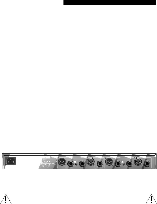
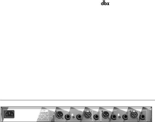
Rear Panel
15 WATTS |
|
PHONE: |
MANUFACTURED UNDER ONE OR MORE OF THE FOLLOWING U.S. PATENTS 4,234,804 4,316,107 4,329,598 4,331,931 4,377,792 4,403,199 4,409,500 4,425,551 4,434,380 4,454,433 4,471,324 4,473,793 OTHER PATENTS PENDING |
||||||
|
|
|
|
CHANNEL 2 |
|
|
CHANNEL 1 |
|
|
|
|
|
TIP |
|
SIDECHAIN |
|
SIDECHAIN |
||
|
|
|
|
|
|
|
|||
|
|
|
RING |
OUTPUTS |
INPUTS |
INSERT |
OUTPUTS |
INPUTS |
INSERT |
|
|
|
TIP=INPUT |
TIP=INPUT |
|||||
|
|
|
|
|
RING=OUTPUT |
|
|
RING=OUTPUT |
|
|
|
|
SLEEVE |
|
+4 dBu |
|
|
+4 dBu |
|
|
|
PROFESSIONAL PRODUCTS |
XLR: |
|
-10 dBV |
|
|
-10 dBV |
|
|
|
A HARMAN INTERNATIONAL |
|
|
|
|
|
|
|
|
|
COMPANY |
PIN 1 |
|
|
|
|
|
|
|
|
SALT LAKE CITY, UTAH |
PIN 2 |
|
|
|
|
|
|
100V |
50/60Hz |
MADE IN USA |
|
|
|
|
|
|
|
120V |
60Hz |
MODEL 166XL |
PIN 3 |
|
|
|
|
|
|
|
|
COMPRESSOR/LIMITER/GATE |
|
|
|
|
|
|
|
INPUT (BALANCED) Jacks:
The Tip/Ring/Sleeve phone jack and XLR-type jack are wired in parallel; either INPUT will accept an audio signal for processing by the 166XL. The phone jack accepts a standard TRS 1/4” phone plug for a balanced input source, or a 2-cir- cuit (Tip/Sleeve) 1/4” phone plug for an unbalanced source. The XLR-type jack is wired pin 2 HOT (+), pin 3 COLD (-) and pin 1 GROUND.
Note: Only one input jack should be used at a time, except for “splitter” applications where one input jack is used as an input and the other input jack is used as an output (see “Using the SIDECHAIN INSERT” section on page 16). Since a given pair of channel input jacks (e.g., Channel 1 XLR INPUT and Channel 1 1/4” INPUT) are internally connected (TIP = Pin 2, RING = Pin 3, SLEEVE = Pin 1), if one of the jacks is unbalanced, then the other jack will be unbalanced. For example, if a 1/4” INPUT jack is used with a mono cable, and is therefore unbalanced, the XLR INPUT jack will also be unbalanced (Pin 3 shorted to ground).
OPERATING LEVEL Switch:
This switch selects between a -10dBV and +4dBu nominal operating level. When the switch is in the in position, a -10dBV operating level is selected. When it is in the out position +4dBu is selected. A -10dBV operating level should be
dbx 166XL COMPRESSOR / GATE |
PROFESSIONAL PRODUCTS |
|
® |
|
|
selected when interfacing with “semi-pro” or low level equipment, while a +4dBu level should be selected when interfacing with “pro” equipment. The switch simultaneously changes the operating levels for both the input and output circuits. Note that the switch is slightly recessed to prevent accidental switching of operating levels while plugging in or unplugging cables.
OUTPUT (BALANCED) Jacks:
The Tip/Ring/Sleeve phone jack and XLR-type jack are wired in parallel; either OUTPUT will send an audio signal to a load. The phone jack accepts a standard TRS 1/4” phone plug for a balanced output load, or a 2-circuit (Tip/Sleeve) 1/4” phone plug for an unbalanced load. The XLR-type jack is wired pin 2 HOT(+), pin 3 COLD (-) and pin 1 GROUND. For proper unbalanced operation, the unused pin (either pin 2 or 3) must be grounded. Nominal output signal level is +4dBu or -10dBV into 600½, and typical maximum output level is +20dBu into 600½ (+20dBm).
Note: A given pair of channel output jacks (e.g., Channel 1 XLR OUTPUT and Channel 1 1/4” OUTPUT) are internally connected (TIP = Pin 2, RING = Pin 3, SLEEVE = Pin 1) and can simultaneously deliver the same signal to two separate loads, but if one of the jacks is unbalanced, then the other jack will be unbalanced. For example, if a 1/4” OUTPUT jack is used with a mono cable, and is therefore unbalanced, the XLR OUTPUT jack will also be unbalanced (Pin 3 shorted to ground). If using both outputs of a given pair simultaneously, the total parallel load on the output should be 600½ minimum.
SIDECHAIN INSERT Jack:
This jack accepts a standard TRS 1/4” phone plug and provides a connection to the 166XL detector path. The RING acts as a Send, carrying a buffered version of the signal present at the 166XL INPUT jack, at an impedance of 2k½. The TIP acts as a Return for equipment to feed the 166XL’s detector circuitry, such as an equalizer for de-essing or frequencysensitive gating/compression. You can also drive the 166XL SIDECHAIN INSERT with the output of most equipment, by using a 1/4” mono phone plug. Input impedance is greater than 10k½.
Note: When a cable is plugged into this jack, it automatically breaks the connection from the INPUT circuit to the 166XL’s detection circuitry. Note: The following Operating Notes section contains several applications for using the sidechain circuit.
AC POWER Receptacle:
This receptacle accepts an IEC-type power cord (as shipped with the unit). Plug the cord into the unit and mains power. Note that the 166XL does not have a power switch. It is recommended that the 166XL be “On” at all times. Power consumption is low. If you do not plan to use the 166XL for an extended period of time, unplug it.
Warning: Be sure to verify both your actual line voltage and the voltage for which your Model 166XL was wired, as indicated on the rear panel of your unit. Connection to an inappropriate power source may result in extensive damage which is not covered by the warranty.
OPERATING NOTES
Expander/Gate Applications
Note: Control settings for each application are suggested as a starting point. Adjust them for your requirements.
Gating Dry Percussive Sounds (e.g., Snare Drum, Kick Drum)
To effectively gate percussive sounds with high-level transients, you need to set the 166XL’s gate controls to ensure that the gate is less sensitive to nearby signals that would cause the gate to open or “false trigger.” Set the RELEASE setting fast enough to enable the gate to close very quickly once the signal falls under the THRESHOLD. The RELEASE can also be used to shape the envelope of the sound.
Note: Fast gating of sustained low frequency signals can result in “chattering.” Because the 166XL is capable of extremely fast gating, make sure the RELEASE time is longer than one full cycle of the gated signal’s fundamental frequency. To eliminate any “chattering,” simplyadjust the RELEASE time to a longer time (slower rate). The proper THRESHOLD setting will also minimize false triggering and “chattering.”
These types of settings are most useful for tightening up drum tracks, removing the “ring” from some drums, or gating out the leakage of one drum through another’s mic.
Gating Sounds That Have Longer Decay (e.g., Cymbal, Piano)
To effectively gate sounds which have more decay after the initial transient, set the RELEASE control slow enough to allow the gate to remain open and capture the signal’s entire envelope.
The gate can also be used to “dry up” a track or mix that has too much reverb or ambience. Set the RELEASE control so that the natural decay of the sound is somewhat truncated.
Changing Sound Quality
The 166XL’s gate can effectively change the sonic character of a sound because it can reduce or otherwise alter the quality of instrumental ambience and reverb. For example, as an instrument stops, its reverberation level will fall through the 166XL’s THRESHOLD setting. It can now be made to die out more quickly - faster than the natural decay (of the sound). Experiment with different THRESHOLD and RELEASE settings to change the “tail” of the sound; a FAST RELEASE setting will nearly eliminate reverb.
Keyed Gating
Keyed gating, that is, controlling the gating of one signal by another, can be used to add dynamics to a sound (e.g., cre-

dbx 166XL COMPRESSOR / GATE
ating perfectly in-sync playing and overdubbing among individual instruments or “fattening” a dynamically weak track). To create two distinct channels of bass guitar for your mix (by splitting the bass signal into two channels and synchronizing one channel of bass guitar with the kick drum), start by feeding one channel of bass directly into the mix and the other into the 166XL’s INPUT. Then key the gate with a signal from the kick drum (connected to the SIDECHAIN INSERT - adjust controls as needed). The gated bass track will now open with each kick, adding punch and dynamics.
This can really tighten up the tracks and add life to the mix.
Another example of keyed gating is using the drum signal to key an oscillator which is set to an appropriate frequency to “tune” and “punch up” the drum sound.
Note: For all keyed gating applications, be aware to adjust the compressor accordingly or bypass it by setting the Compressor RATIO fully counterclockwise to 1:1
Frequency-Sensitive Gating
Frequency-sensitive gating lets you use the SIDECHAIN INSERT to tune the response of the gating action. For example, if you’re gating a kick drum in a track with lots of leakage, you can tune in to the frequency of the kick with an outboard EQ and the gate will respond only to that drum. Feed the kick drum signal both directly into the gate and also through an equalizer which is connected to the SIDECHAIN INSERT. With the equalizer adjusted so that only the desired signal is strong at the SIDECHAIN INSERT, the gate becomes even more selective in opening.
Basic Compressor Applications
Note: Control settings for each application are suggested as a starting point. Adjust them for your requirements. In general, the “smoothest” compression is achieved with the OVEREASY and AUTO buttons In, while the most “aggressive” compression is achieved with a Hard Knee fast setting (i.e., OVEREASY button Out with fast ATTACK and RELEASE times).
To compress a mix, begin with a low RATIO setting, THRESHOLD set for a few dB of Gain Reduction, and SLOW Attack and Release, OVEREASY and CONTOUR buttons In.
Smoothing Out Variations in Microphone Levels
Variations in signal level can occur when the distance between a vocalist and a mic changes, or when the dynamics of a voice changes relative to a vocalist’s range. To smooth out these variations, start with the 166XL in OverEasy mode (OVEREASY button In) with a medium attack time and a fairly slow release time and adjusted for a low to medium compression RATIO (e.g., 4:1). Many people prefer the use of AUTO mode for vocals rather than setting the attack and release controls manually. Adjust the THRESHOLD control so that the GAIN REDUCTION meters show 6dB to 10dB of gain reduction, then increase the RATIO if necessary. Due to the gentle OverEasy characteristic of your 166XL you will find that even fairly high ratios are handled transparently. If the lower energy of the vocals is compressed too much (e.g., if the voice sounds too thin or its lower register presence is lost), press the CONTOUR button In to allow more of the original low energy to pass through the 166XL unaffected.
Smoothing Out Variations (and Increasing Sustain) in Musical Instrument Levels (e.g., Bass Guitar, Electric Guitar, Synthesizer)
To achieve a smoother electric (or electronic) bass sound, compress the instrument’s output with a RATIO of approximately 4:1, then adjust the THRESHOLD control for 10dB to 12dB of gain reduction. Compression lessens the loudness variations among the strings and increases the bass’ inherent sustain. Other instruments, such as horns, vary in loudness depending on the note being played, and benefit similarly. Note that if the compressed bass sounds smooth, but too thin for your needs, try pressing In the CONTOUR button to thicken the sound.
To control untimely volume shifts in “hot” guitar or synth parts and to keep them from overloading your tape deck or mixer during recording and live performances, start with a slow Hard Knee compression, the RATIO at approximately 5:1 and the THRESHOLD set to the average maximum level of the track - this will ensure that only the offending “hot” part is compressed. Use CONTOUR, if necessary.
To add sustain to guitar or synthesizer string sounds, begin with a higher RATIO (from 10:1 to °:1), then adjust the THRESHOLD control to taste. For example, to alter the envelope of a synthesizer sound that has a bite on its attack, but ends with a long release time, begin by playing slow, but steady, synth stabs or chords, while compressing the sound heavily (with a higher RATIO). Heavy compression of guitars and synths, as they are being recorded to digital formats, can often help revive their sense of “analog life.”
Fattening Kick Drums and Compressing Other Drums
Weak, flabby kick drums often have too much boom, and not enough slap. To tighten them up, start with the 166XL adjusted for a medium to high RATIO (e.g., 6:1), adjust the THRESHOLD control so that the GAIN REDUCTION meters show 15dB of gain reduction, then increase the RATIO if necessary. In OverEasy mode, the 166XL takes slightly longer to react than in Hard Knee mode, and will therefore emphasize the slap at the beginning of the note and reduce the boominess of its body. The 166XL also works well for tightening snare drums and tom toms and can be used with drum machines to effectively alter the character of any electronic drum sound.
Cymbals and tom-toms can be effectively compressed (using the 166XL’s Sidechain) to help prevent analog tape sat-

dbx 166XL COMPRESSOR / GATE |
PROFESSIONAL PRODUCTS |
|
® |
|
|
uration. Split the drum signal, sending one channel directly to the 166XL’s INPUT and the other channel to an equalizer (e.g., dbx’s 20 Series or 30 Series Graphic Equalizer). Then connect the equalizer’s output to the 166XL’s SIDECHAIN INSERT. The equalizer can be adjusted for boost with a peak of about 5kHz, causing the cymbal to be compressed on a very loud crash, stopping tape saturation at high frequencies, where there is less headroom. However, gentle tapping of a drumstick or brushing of the cymbal will not be affected. Assuming the tom-tom is a lower frequency instrument and can be better tolerated by the tape, it has less need for compression. Equalization in the Sidechain circuit means that the compressor is not triggered as readily by a loud tom-tom beat as by an equally loud cymbal crash. Refer to the next page for more Sidechain applications.
For drum kit submixes (e.g., mixing multiple drum tracks to two tracks while using both channels of a 166XL for compression), consider backing off the RATIO on each channel (down to 2:1) to avoid an excess of cymbal “splattering.” In larger multitracking systems, compress the kick and snare separately. A further possibility is to heavily compress a stereo submix of toms and leave the remaining percussives unaffected.
Raising a Signal Out of a Mix
Since reducing dynamic range increases the average signal level by a small amount, a single track can be raised out of a mix by boosting its level slightly and applying compression. Start with a 2:1 RATIO and a relatively low THRESHOLD setting (-20dBu). Adjust both controls as necessary.
Compressors have also been used to bring vocals to the forefront of a mix in volume-restricted studios (e.g. home studios). Start by adding a foam windscreen to the mic (if it doesn’t have one). Set the RATIO to 10:1 and the THRESHOLD to -10dBu. With your mouth approximately 2 inches from the mic, sing the vocal part, but with less volume than normal. Use phrasing to give the part some intensity. An equalizer (e.g., a dbx 20 Series Equalizer or dbx 30 Series Graphic Equalizer) or a vocal effects device (e.g., reverb, delay, distortion) can be added to further define the performance.
It is also possible to separate certain vocals or instruments from a mono program already mixed: refer to frequencyweighted compression on page 9.
Note: When compressing a stereo program with a 166XL, the factors affecting a compression curve and the actual RATIO and THRESHOLD settings, are like those previously covered with reference to single channels of program material. However, it will generally be found that large amounts of compression are more audible in a mixed stereo program than they might be on the separate tracks that were mixed to create the program.
Preventing Analog Tape Saturation
With programs of widely varying levels, compression can prevent recording levels (e.g., cymbal tracks in a final mix or drum kit submix) from saturating tape tracks (see frequency-weighted compression, on page 9).
Preventing Digital Overload
Digital recorders and samplers produce audible distortion when they exceed their headroom (i.e., the range above their maximum operating level). The 166XL effectively ensures that audio input does not overload a digital recorder’s A/D (analog-to-digital) converters. The 166XL can perform this function quietly enough for all digital media. To use the 166XL so that no changes in gain occur unless an emergency arises (wildly excessive levels), set Hard Knee mode On, the RATIO to °:1, and the THRESHOLD to the highest permissible level.
Note: PeakStop limiting can also be used to prevent raucous-sounding digital overload.
Speaker Protection (Auditoriums, Churches, Mobile DJs and Sound Systems)
Compressors are frequently used to prevent excessive program levels from distorting power amps and/or damaging drivers in a sound-reinforcement system (whether you’re doing auditorium, church, or club sound engineering, or are a mobile DJ, or like to push the limits of your home’s audio entertainment center). Set the 166XL for limiting (Hard Knee mode On, with a RATIO of 10:1 or greater) and adjust the THRESHOLD to provide 15dB or more of compression (just a few dB below the input clip). For low-level signals, the 166XL won’t change gain, but if large signals come along, the gain will be reduced to prevent clipping and save sensitive system components from excessive heat buildup or other type of damage.
In circumstances where the 166XL is expected to cause no change in gain unless an emergency arises (wildly excessive levels), some operators set Hard Knee mode On, the RATIO to °:1, and the THRESHOLD to the highest permissible level. As with preventing digital overload, the 166XL’s PeakStop limiter can be used instead of or in combination with the 166XL’s compression.
As a general rule, compressors should be as close to the amplifiers as possible in the signal chain. If the 166XL is placed before the EQ (equalizer), for example, a potentially damaging boost in the EQ won’t be seen by the 166XL and the speakers may be damaged. (see Multi-way speaker systems, page 10). For maximum sound pressure levels, large sound reinforcement systems frequently use a separate compressor on each output of the electronic crossover(s). For a stereo sound-reinforcement system, one 166XL can be used for each stereo band (low, low-mid, mid, etc.).
Raising Average Level in PA Systems
Limiting (i.e., compression at high ratios like °:1) also benefits intelligibility by allowing low-level input signals to be reproduced through the system at higher volume. In a musical performance, this provides additional intimacy so that a
dbx 166XL COMPRESSOR / GATE
vocalist’s whispers are heard more clearly. The OverEasy curve available with the 166XL permits a very high amount of compression (RATIO of 10:1 or greater) to be used in many situations. This allows dynamic speakers, vocalists and other musicians to concentrate on their presentation or performance without worrying about the ill effects of volume changes.
Using Your EQ to Reduce Feedback in Live Settings (Indoor and Outdoor Concerts,
Churches)
You can use your 166XL and EQ (equalizer) to reduce feedback in clubs, churches, outdoor concerts and other live settings. Patch or insert the 166XL into the main output of a mixer, set the 166XL to Hard Knee mode and slowly increase OUTPUT GAIN until the first feedback “ring” occurs, then set up the 166XL with its RATIO at °:1 and THRESHOLD low. The 166XL will catch the first feedback ring and hold it as a constant tone so you can adjust your EQ to minimize it. Continue to increase your console gain and set your EQ until the next 3 or 4 “ring” frequencies have been compensated for.
The 166XL as a Line Amplifier
To use the 166XL as a line amplifier, adjust the RATIO control fully counterclockwise (1:1 position), THRESHOLD fully clockwise (+20), PeakStop to +20 and OUTPUT GAIN to whatever setting is required for the application. Remember, excessive gain may lead to output clipping of high level signals. To add compression, adjust the RATIO and the THRESHOLD controls to the desired settings.
Frequency-Weighted Compression (Sidechain Application)
It is possible to separate certain vocals and instruments from a mix by frequency-weighted compression. With an equalizer (such as a dbx 20 Series or 30 Series EQ) inline ahead of the SIDECHAIN INSERT (but not in the audio path), the equalization settings do not shift the timbre or frequency response of the audio signal. They merely alter the threshold response of the compressor on a “frequency-weighted” basis.
With this arrangement, raising certain frequencies on the equalizer causes them to be suppressed in the audio signal. A relatively high THRESHOLD setting can allow normal sounds to be unaffected while solo and very loud sounds are compressed. (Of course, when compression occurs, the level of the entire program is affected - however, if the 166XL’s CONTOUR button is pressed in, even more of the signal’s lower energy can be preserved.) Depending on the THRESHOLD setting, lower amplitude fundamentals or harmonics will not cause compression, and the program is not subject to the phase shift normally caused by program equalization.
166XL6A
INPUT OUTPUT
SIDECHAIN
INSERT
OUTPUT
SOURCE
EQ
Figure 3: Frequency-Weighted Compression
When recording cymbals and tom-toms, a compressor with an equalizer in the Sidechain path can help prevent analog tape saturation. The equalizer can be adjusted for boost with a peak of about 5kHz, causing the cymbal to be compressed on a very loud crash, stopping tape saturation at high frequencies, where there is less headroom. However, gentle tapping of a drumstick or brushing of the cymbal will not be affected. Assuming the tom-tom is a lower frequency instrument and can be better tolerated by the tape, it has less need for compression. Equalization in the Sidechain circuit means that the compressor is not triggered as readily by a loud tom-tom beat as by an equally loud cymbal crash.
The converse of the above EQ technique may be used: dipping the equalizer bands causes any sound with dominant energy in the affected register to pull the level up because the 166XL will detect a need for less compression.
De-Essing
To apply de-essing to vocals (i.e., a reduction of sibilance), use a parametric equalizer (e.g., a dbx 242) in the SIDECHAIN circuit and set it to boost the specific frequency range where the vocal “hiss” or lisp occurs (generally in the 4kHz - 6kHz region). This pre-emphasizes the already “hissy” vocal input to the Sidechain. Used in conjunction with a moderate to high THRESHOLD and RATIO, and a fast Attack and Release setting, this arrangement greatly attenuates the “essing” without affecting the basic sound quality or balance of the voice. While it is true that all frequencies are lowered in level when the compressor is triggered, generally the “sss” sound occurs alone, before or after the dominant tone in the voice.
dbx 166XL COMPRESSOR / GATE |
PROFESSIONAL PRODUCTS |
|
® |
|
|
Increasing Sustain
To increase the sustain of a musical instrument (e.g., a guitar or bass), use an equalizer in the Sidechain circuit and boost the EQ in the dominant frequency range of the instrument. Set the 166XL for slow Hard Knee compression, with a fairly low THRESHOLD and a moderate RATIO.
Multi-Way Speaker Systems
If a single compressor is to be used with a multi-way speaker system (i.e., before the crossover, after the EQ), the system operator is faced with the problem of keeping levels below the point of damage of the most sensitive part of the system. If, for example, mid-range drivers are frequently damaged, the whole system must be operated at a lower sound-pres- sure level, or additional mid-range drivers must be added. By inserting an equalizer in the Sidechain path to the 166XL, it can be made more sensitive to frequencies in the range handled by the sensitive drivers. The system can then be run at higher levels and will only be dropped back when damaging signals are present.
Using a Filter in the Sidechain Circuit
The results of inserting a filter in the Sidechain circuit are basically the same as obtained with an equalizer, as previously described. Those frequencies passed by the filter are subject to compression (or at least they are subject to considerably more compression than those frequencies outside the passband). Because a passive filter can have insertion loss, it may be necessary to lower the 166XL’s THRESHOLD setting to maintain a given amount of gain reduction within the filter passband; this can be determined by monitoring the 166XL’s THRESHOLD LEDs.
Pre-Emphasis for Broadcast Applications
By inserting a pre-emphasis filter network in the Sidechain path of a 166XL processing pre-emphasized audio, higher levels can be run within the headroom limitations of the broadcast chain.
CONNECTING THE 166XL TO YOUR SYSTEM
Basic Connection
15 WATTS |
|
PHONE: |
MANUFACTURED UNDER ONE OR MORE OF THE FOLLOWING U.S. PATENTS 4,234,804 4,316,107 4,329,598 4,331,931 4,377,792 4,403,199 4,409,500 4,425,551 4,434,380 4,454,433 4,471,324 4,473,793 OTHER PATENTS PENDING |
||||||
|
|
|
|
CHANNEL 2 |
|
|
CHANNEL 1 |
|
|
|
|
|
TIP |
|
SIDECHAIN |
|
SIDECHAIN |
||
|
|
|
RING |
OUTPUTS |
INPUTS |
INSERT |
OUTPUTS |
INPUTS |
INSERT |
|
|
|
TIP=INPUT |
TIP=INPUT |
|||||
|
|
|
|
|
RING=OUTPUT |
|
|
RING=OUTPUT |
|
|
|
|
SLEEVE |
|
+4 dBu |
|
+4 dBu |
||
|
|
|
|
|
|
|
|||
|
|
PROFESSIONAL PRODUCTS |
XLR: |
|
-10 dBV |
|
|
-10 dBV |
|
|
|
A HARMAN INTERNATIONAL |
|
|
|
|
|
|
|
|
|
COMPANY |
PIN 1 |
|
|
|
|
|
|
|
|
SALT LAKE CITY, UTAH |
PIN 2 |
|
|
|
|
|
|
100V |
50/60Hz |
MADE IN USA |
|
|
|
|
|
|
|
120V |
60Hz |
MODEL 166XL |
PIN 3 |
|
|
|
|
|
|
|
|
COMPRESSOR/LIMITER/GATE |
|
|
|
|
|
|
|
The 166XL has balanced inputs and outputs, and can be used with any line-level device. Some common examples include: mixing consoles, musical instruments, patch bays and other signal processors. For more specific cabling information, refer to Installation Considerations, page 18.
For all connections, refer to the following steps:
1.Turn Off all equipment before making any connections.
2.Mount the 166XL in a 1U rack space (Optional).
The 166XL requires one rack space (height) and 1 rack space (width). It can be mounted above or below anything that doesn’t generate heat, since it requires no special ventilation. Ambient temperatures should not exceed 113˚F when equipment is powered.
Caution: Never remove the cover. There are no user-serviceable parts inside, and you run the risk of an electric shock.
3. Make connections via XLR or 1/4” TRS jacks according to your requirements.
Typical patch points include: a mixer’s channel or subgroup inserts when using the 166XL on individual instruments or tracks; the mixer’s main outputs or bus inserts when mixing; an instrument preamp’s effects loop when using the 166XL for guitar or bass; main outs of a submixer (e.g., keyboard mixer) as the signal is sent to main mixer; between a DAT’s output and an analog cassette input. When using a chain of processors, the 166XL may be placed either before or after effects or dynamic processors. However, if you are using the 166XL for speaker protection, the compressor should be as close to the amplifier as possible in the signal chain. We recommend you use common sense and experiment with different setups to see which one provides the best results for your needs.
Note: Never connect the 166XL’s input to the speaker output of an instrument or power amplifier.
4. Power On the unit: Securely connect the AC power cord to the unit and mains power.
Note: Check the line voltage. The unit is shipped for 115V or 230V operation. Refer to the unit’s rear panel to verify your unit’s precise line voltage.

dbx 166XL COMPRESSOR / GATE
Using the SIDECHAIN INSERT
The SIDECHAIN INSERT can be used to control the compressor or the expander/gate by signals other than the audio input (via an auxiliary device, such as an equalizer). Common Sidechain applications include keyed gating, frequency-sen- sitive gating and frequency-weighted compression. These topics are covered in detail in the previous pages of this manual. Certain Sidechain applications may require special cabling.
For example, to set up your 166XL for frequency-sensitive gating or frequency-weighted compression, you must feed an equalizer’s input with the same signal fed to the 166XL’s INPUT, and then connect the equalizer’s output to the 166XL’s SIDECHAIN INSERT jack (Figure 3). Providing the signal to both the 166XL’s INPUT and the equalizer can be accomplished in several different ways: (1) use an insert cable plugged into the SIDECHAIN INSERT jack. The SEND goes to the input of the EQ. The RETURN goes to the output of the EQ; (2) use a Y-cable to feed the audio source to both the 166XL INPUT and the equalizer input; (3) feed the signal to one of the 166XL’s INPUT jacks and use the compressor channel’s parallel INPUT jack to drive the equalizer (e.g., if the audio source feeds into Channel 1’s 1/4” INPUT jack, use Channel 1’s XLR INPUT jack to feed the signal to the equalizer); (4) if the audio source can internally split its output signal (e.g., some synthesizers can send the same signal from two outputs), plug a cable into each output and feed one cable to the 166XL INPUT and the other to the equalizer.
Specific System Connections
The 166XL has balanced inputs and outputs, and can be used with any balanced or unbalanced line-level device. Some common examples include: mixing consoles, musical instruments, patch bays, and other signal processors.
Mixing Board
If you wish to compress a particular track of a multitrack recording or one channel of a live performance, connect the 166XL INPUT to the audio source’s output jack while the 166XL OUTPUT can be directly connected to a line input jack (balanced or not) or the 166XL’s INPUT and OUTPUT can be wired to an Insert point. In the latter case, the signals will most likely be unbalanced.
It is important to note that the amount of compression is directly related to the level of the input signal. However, depending upon your system’s setup, it may not always be clear as to what volume controls in your chain affect input level and which affect output level. If the 166XL is connected so that compression occurs before the mixer’s volume controls (e.g., the 166XL is connected directly between an audio source and the mixer input, or the 166XL is connected to mixer inserts that are “pre-fader”), you can boost or cut the input level by adjusting the source’s volume control (e.g., a synthesizer’s volume control) and boost the track’s output level using the 166XL’s OUTPUT GAIN control or the mixer’s volume fader (the latter here is great for track fade-outs). However, if the 166XL is connected to “post fader” mixer inserts, adjusting the mixer’s volume fader changes the input level and the amount of compression. If you would rather have this volume fader control output, we suggest that you set up the compressor directly between the source and the mixer channel’s input. This way, you can use the instrument’s volume control to define the input level and amount of compression and the mixer’s volume fader to change only the overall volume of the track.
Musical Instruments (e.g., Electric Guitar, Bass, Keyboards, Electric-Acoustic Instruments)
The output of an electric guitar is sometimes not “hot” enough to drive the 166XL’s INPUT. When this is the case, switch the rear panel +4/-10 switch to the IN position which will boost the low level signal by approximately 12dB. If this is still not enough boost then you should use the “PREAMP OUT” of your guitar amp (if so equipped), or the output of some other device that is designed to accept low-level instrument inputs (including various foot pedal effects, acoustic pickup preamps, and some rack mount audio products). Such sources can be balanced or unbalanced - this is no problem for the 166XL.
Microphones, bass guitars, and electric-acoustic instruments, also typically have low-level outputs. With most setups they require signal boost to drive the 166XL’s INPUT. For example, when recording voice directly to a portable tape deck, a mic preamp placed between the mic and the 166XL (which is then fed to one of the recorder’s inputs) can boost the signal for the 166XL as well as provide a high level signal to the tape deck.
Keyboards, samplers, drum machines and sound modules typically produce a line-level signal and can be connected directly from the instrument’s output to the 166XL’s INPUT.
Note: DO NOT CONNECT the 166XL’s input to the speaker output of an instrument or power amplifier. Severe damage to system components may result.
Patch Bay
In the studio, the 166XL may be connected to a patch bay (such as a dbx PB-48) to allow it to be used anywhere in the studio system. If your studio is not fully balanced, you must ground the unused balanced output conductor: XLR pin (either pin 2 or 3) or the ring of a 1/4” stereo phone jack. Note that grounding pin 2 of the XLR jack reverses the phase through the 166XL.
dbx 166XL COMPRESSOR / GATE |
® |
PROFESSIONAL PRODUCTS |
Sound Reinforcement
To compress a live mix or to protect loudspeakers, connect the 166XL between the source (mixing board or distribution amp) and the power amp(s). If multi-way loudspeakers with low-level electronic crossovers are used, the 166XL(s) should go after the crossover(s). For a stereo system, you can separately stereo couple the two high band crossovers, low band crossovers, etc. If limitations require that you use a single 166XL channel before a crossover, adding an equalizer to the sidechain may provide some additional protection to your high frequency components (see “Speaker Protection,” page 8).
INSTALLATION CONSIDERATIONS
Input/Output Cable Configurations
Hookups and Cabling
The 166XL is a balanced (differential) unit designed for nominal +4dBu or -10dBV levels; inputs and outputs are 1/4” tip/ring/sleeve (TRS) phone jacks and XLR-type jacks. The 166XL can be used with either balanced or unbalanced sources and outputs can be used with either balanced or unbalanced loads, provided you use proper cabling.
A balanced line is defined as two-conductor shielded cable with the two center conductors carrying the same signal but of opposite polarity with respect to ground. An unbalanced line is generally a single-conductor shielded cable with the center conductor carrying the signal and the shield at ground potential.
Input Cable Configurations
The 166XL has an actual input impedance of >40k½ in balanced or unbalanced configurations. This makes the 166XL audio input suitable for use with virtually any source impedance, low or high. The 166XL’s input jacks are wired in parallel. The phone jack TIP (+) connection is internally wired to the XLR pin 2, the RING (-) is wired to pin 3, and the SLEEVE (shield) is wired to pin 1. Note that pins 2 and 3 are the reverse of certain older dbx and other manufacturer’s equipment, but if the same connection is used at both the input and the output, the signal will be correctly polarized (“in phase”).
Reversing the input wires to the input terminals will result in the output signal polarity being the opposite of the input signal (“180˚ out of phase”).
Output Cable Considerations
The model 166XL’s outputs are wired in parallel: either the XLR-type OUTPUT jack or the 1/4” stereo phone jack are capable of driving a 600½ load. The phone jack TIP (+) connection is internally wired to the XLR pin 2, the RING (-) is wired to pin 3, and the SLEEVE (shield) is wired to pin 1. Note that pins 2 and 3 are the reverse of certain older dbx and other manufacturer’s equipment, but if the same connection is used at both the input and the output, the signal will be correctly polarized (“in phase”).
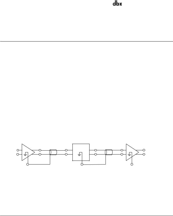
166XL
166A
SIGNAL FLOW 
Figure 4: Signal Flow (Balanced Connection)
Grounding
For maximum hum rejection with a balanced source, avoid common grounding at the 166XL’s input and output. Most balanced (3-conductor) cables have the shield connected at both ends. This can result in ground loops which cause hum. If hum is a problem, try disconnecting the shield on one or more of your cables, preferably at the input of a device, not at the output: Ground the shield of the input cable at the source device (leaving it unconnected at the 166XL’s INPUT) and ground the shield of the output cable to the ground terminal of the 166XL (leaving it unconnected at the receiving device). The shield is pin 1 on the XLR, SLEEVE on a 1/4” TRS.
TECHNICAL SUPPORT, FACTORY SERVICE
The 166XL is an all-solid-state product with components chosen for high performance and excellent reliability. Each 166XL is designed, assembled, tested, burned in and calibrated at the factory in the USA and should require no internal adjustment of any type throughout the life of the unit. We recommend that your 166XL be returned to the factory only after referring to the manual and consulting with Customer Service.
Our phone number, fax number and address are listed on the rear cover. When you contact dbx Customer Service, be

dbx 166XL COMPRESSOR / GATE
prepared to accurately describe the problem. Know the serial number of your unit - this is printed on a sticker attached to the unit.
Note: Please refer to the terms of your Limited Two-Year Standard Warranty, which extends to the first end-user. After the warranty expires, a reasonable charge will be made for parts, labor, and packing if you choose to use the factory service facility. In all cases, you are responsible for transportation charges to the factory. dbx will pay return shipping if the unit is still under warranty.
Shipping Instructions:
Use the original packing material if it is available. Mark the package with the name of the shipper, and with the following words in quotes in red: “DELICATE INSTRUMENT, FRAGILE!” Insure the package properly. Ship prepaid, not collect. Do not ship parcel post. (If you do not plan to save the packaging material, please recycle it.)
Registration Card and User Feedback
We appreciate your feedback. After you have an opportunity to use your new 166XL, please complete the Registration Card and return it.
FRANÇAIS
INTRODUCTION
Nous vous félicitons d’avoir choisi le processeur dbx 166XL Dynamics Processor. Le 166XL permet un contrôle total de la dynamique du signal sonore, offrant notamment deux canaux de réduction de bruit (noise gate), compression OverEasy® ou compression traditionnelle Hard Knee et limitation de crêtes PeakStop®. Il s’adresse aux studios, aux sociétés de sonorisation, aux musiciens ou à quiconque recherchant un dispositif simple et rapide offrant un traitement de signal de qualité. Nous vous invitons à lire ce manuel pour tirer le meilleur profit du processeur. Caractéristiques :
•Réduction de bruit, compression et limitation de crêtes en mode stéréo ou dual mono.
•Sélecteur OverEasy®/Hard Knee - permet de choisir entre le célèbre mode de compression OverEasy et le mode « Hard Knee », plus traditionnel, proposé sur les modèles dbx 160, 161 et 162.
•Circuit expanseur/Gate - temps de maintien variable et seuil maximal de +15 dBu.
•Sélecteur passe-bas (touche CONTOUR) sur le circuit d’insertion Sidechain - conseillé lors de la compression de sons mixés pour éviter que les signaux de basse fréquence ne créent des « trous » dans le son.
•Limiteur PeakStop® - contrôle les pointes de signal à la sortie du 166XL indépendamment de tout autre réglage. Placé en aval des circuits de compression, porte, gain de sortie et autre, le circuit PeakStop permet de fixer une limite absolue pour les crêtes du signal de sortie.
•Détection de valeur efficace (« True RMS Level ») - mesure la puissance d’un son de façon musicale, à la manière de l’oreille humaine, produisant de meilleurs résultats que la détection de crête ou de valeur moyenne.
•Touche de by-pass du système sur les deux canaux - pour assurer la continuité du signal audio même lorsque l’appareil est débranché ou pour comparer des signaux traités et non traités.
•Affichage GAIN REDUCTION à diodes électroluminescentes 10 segments (jusqu’à 30 dB)
•Entrées et sorties symétriques Jack 6,35 stéréo et XLR
•Connexions d’insertion Sidechain séparées - pour l’utilisation d’un processeur ou d’un signal externe pour la commande du circuit de compression ou d’expansion.
•Commande en courant continu des paramètres - le signal ne passe à travers aucun des potentiomètres. Toutes les fonctions sont contrôlées par courant continu, ce qui élimine tout risque d’apparition de bruit de potentiomètre au fil du temps.
dbx 166XL COMPRESSOR / GATE |
® |
PROFESSIONAL PRODUCTS |
VÉRIFICATION
S’assurer que l’emballage du 166XL contient les articles suivants :
•166XL Dynamics Processor
•cordon d’alimentation secteur
•manuel de l’utilisateur
•carte d’enregistrement
COMMANDES
Face Avant
GAIN REDUCTION (dB)
BELOW ABOVE |
BELOW ABOVE |
30 25 20 15 12 10 8 6 4 2 |
ABOVE |
B |
CHANNEL ONE
|
-25 |
|
|
-20 |
-10 |
0 |
2:1 |
|
|
|
|
|
|
0 |
|
|
|
+10 |
|
-45 |
|
-10 |
|
|
1.3:1 |
4:1 |
|
|
|
|
-10 |
|
|
+10 |
+5 |
+15 |
-45 |
||
|
|
-30 |
|
|
+10 |
|
|
|
|
|
|
|
|||||||
|
|
|
|
|
|
|
|
|
|
|
|
|
|
|
|
|
Stereo |
||
|
|
SC Enable |
|
Contour |
|
|
OverEasy |
|
|
|
Auto |
|
|
|
|
Bypass |
|
Couple |
|
OFF |
dBu +15 |
Fast |
Slow |
-40 |
dBu |
+20 |
1:1 |
:1 |
Fast |
Slow |
Fast |
Slow |
-20 |
dB |
+20 |
|
0 |
dBu +20 |
|
THRESHOLD |
RELEASE |
THRESHOLD |
RATIO |
|
ATTACK |
RELEASE |
OUTPUT GAIN |
|
PEAKSTOP |
MASTER |
|||||||||
|
EXPANDER/GATE |
|
|
|
|
|
|
COMPRESSOR |
|
|
|
|
|
|
LIMITER |
||||
|
|
|
|
|
|
|
|
|
|
|
|
|
|
||||||
Section NOISE/GATE
Potentiomètre THRESHOLD (seuil) et témoins BELOW/ABOVE (au-desous/au-dessus) :
Cette commande permet de régler le seuil à partir duquel la porte s’ouvre pour permettre le passage du signal à travers l’appareil. Tourner le bouton à fond dans le sens inverse des aiguilles d’une montre (jusqu’à OFF [désactivé]) pour permettre le passage des signaux sans atténuation et, en pratique, contourner la porte. Si ce bouton est tourné à fond dans le sens des aiguilles d’une montre, la porte atténue les signaux d’entrée en-dessous de +15 dBu.
Les deux Led de la section Expander/Gate indiquent la position du signal d’entrée par rapport au seuil choisi. La Led rouge (BELOW) s’allume lorsque le signal est EN-DESSOUS du seuil, la Led verte (ABOVE) s’allume lorsque le signal est AU-DESSUS du seuil.
Remarque : Le temps d’attaque du circuit expander/Gate du 166XL (qui détermine la vitesse à laquelle le signal est rétabli après atténuati on) est extrêmement court, suffisamment pour permettre le passage des transitoires lors de l’attaque d’une note, d’un chant ou d’un mot parlé.
Remarque : Le taux d’expansion est fixé de façon interne à environ 10:1. Ce taux permet l’élimination des artefacts généralement associés à la commutation courante. L’atténuation est supérieure à 50 dB.
Sidechain active:
Cette touche active les connecteurs de sidechain, permettant le traitement externe du signal de détecteur. Elle n'a aucun effet s'il n'y a rien branché à la boucle de sidechain ; cependant la touche s'illumine indiquant que le sidechain est actif.
Commande RELEASE (relâchement) :
Cette commande permet de déterminer le temps de fermeture de la porte une fois que le signal d’entrée (INPUT) ou d’insertion (SIDECHAIN INSERT) passe en-dessous du seuil. La position SLOW est utile pour la réduction des bruits présents derrière le chant ou les instruments acoustiques. La position FAST permet d’accentuer la netteté des percussions (grosse caisse ou caisse claire, par ex.) et d’empêcher les autres instruments de déborder sur les pistes des percussions.
Remarque : la vitesse de coupure va en « s’accélérant » dans la mesure où le nombre de dB/s augmente de façon continue pendant la fermet ure de la porte.
Touche et led CONTOUR :
Lorsqu’on enfonce cette touche, on rend le circuit de détection du 166XL moins sensible aux signaux basse fréquence, afin d’éviter que ceux-ci ne provoquent des « trous » dans le son, particulièrement pour des signaux mixés. Lorsque la touche CONTOUR est relâchée, le détecteur du 166XL est indépendant de la fréquence. La Led CONTOUR s’allume lorque la touche CONTOUR est enfoncée.
Section COMPRESSEUR
Indicateur GAIN REDUCTION :
Il affiche la valeur dont le signal est atténué par le compresseur et/ou par la porte.
Témoins THRESHOLD (seuil) :
Ces trois Leds indiquent la position du signal d’entrée par rapport au seuil de compression. La Led verte (BELOW) s’allume lorsque le signal est en-dessous du seuil et la Led rouge (ABOVE) lorsqu’il est au-dessus du seuil. En mode OverEasy, la Led orange s’allume lorsque le signal est dans la plage OverEasy (voir figure 2).
dbx 166XL COMPRESSOR / GATE
THRESHOLD :
Ce potentiomètre permet de choisir un seuil de compression compris entre -40 dBu (7,8 mVeff) et +20 dBu (7,8 Veff). Lorsque la commande THRESHOLD de la section COMPRESSOR est réglée sur +20 dB, seules les pointes de signal les plus élevées subiront une compression (lorsque le sélecteur RATIO est réglé sur le taux de compression 1:1, alors le compresseur est désactivé, quel que soit le niveau de seuil choisi).
En mode Hard Knee (touche OVEREASY relâchée), la commande THRESHOLD définit un niveau de référence audessus duquel les signaux d’entrée seront compressés par le circuit de gain du 166XL de la façon déterminée par le réglage de la commande RATIO. Les signaux d’entrée qui sont en-dessous de ce niveau traversent le 166XL sans y être modifiés (à l’exception du gain fixe déterminé par le réglage de OUTPUT GAIN). Voir figure 1.
En mode OverEasy (touche OVEREASY enfoncée), les signaux activent graduellement le circuit de gain du 166XL à mesure qu’ils se rapprochent du seuil de référence fixé par la commande THRESHOLD. Ils ne subissent une compression complète, selon le taux correspondant au réglage de la commande RATIO, qu’au delà du seuil de référence fixé par THRESHOLD. Le mode OverEasy ne présente pas de point défini à partir duquel le signal est compressé et le réglage du seuil (THRESHOLD) correspond à un point de la caractéristique de transfert entrée/sortie à mi-chemin entre le début de la compression et le point où la caractéristique de transfert présente un taux de compression égal au réglage de la commande RATIO. La figure 2 présente des courbes de compression OverEasy et indique comment elles se rapportent à l’état des Leds THRESHOLD.
Touche OVEREASY :
Enfoncer cette touche pour choisir le mode de compression OverEasy®. La Led orange THRESHOLD s’allume lorsque le signal est dans la plage OverEasy. Lorsque cette touche est relâchée, le 166XL fonctionne en compresseur/limiteur Hard Knee (la Led orange OverEasy est active en mode OverEasy uniquement).
En mode Hard Knee, le seuil de compression correspond au niveau au-dessus duquel le signal commence à être compressé. Voir figure 1.
En mode OverEasy, le seuil de compression se situe à mi-chemin de la plage de compression OverEasy, comme l’indique la figure 2.
Commande RATIO :
Tourner ce bouton dans le sens des aiguilles d’une montre pour augmenter le taux port compris entre 1:1 (pas de compression) et °:1 (pas d’augmentation du niveau de tions du niveau d’entrée au-dessus du seuil).
de compression. Il s’agit d’un rapsortie, quelles que soient les varia-
OUTPUT LEVEL (dB)
+20
+15
+10
+5
0
-5
-10
-15
1:1 Unity
RED
Above Threshold
2:1
4:1
20:1
 :1
:1
Rotation Point Threshold
GREEN
Below Threshold
OUTPUT LEVEL (dB)
+20
+15
+10
+5
0
−5
−10
−15
|
|
|
|
|
|
|
1:1 |
|
|
|
|
|
|
|
2:1 |
|
|
|
|
|
|
|
4:1 |
|
|
|
|
|
|
|
:1 |
|
|
|
|
|
|
R |
RED |
|
|
|
|
|
|
|
|
|
|
|
|
|
E |
|
|
|
|
|
|
B |
|
Above Threshold |
|
|
|
|
|
M |
|
|
|
|
|
|
|
A |
|
|
|
|
|
E |
E |
N |
|
OverEasy Range |
|
|
R |
|
|
|
|
||
|
|
|
|
|
|
||
G |
|
|
|
|
|
|
|
|
|
|
|
|
|
|
|
Below Threshold
-15 -10 -5 0 +5 +10 +15 +20 |
−15 −10 −5 0 +5 +10 +15 +20 |
INPUT LEVEL (dB) |
INPUT LEVEL (dB) |
Figure 1 : Mode de compression Hard Knee |
Figure 2 : Mode de compression OverEasy |
Caractéristique de transfert et état des Leds de seuil |
Caractéristique de transfert et état des Leds de seuil |
Lorsqu’un signal d’entrée dépasse le niveau de seuil défini par le réglage de THRESHOLD, cette commande détermine l’importance en dB de la variation du signal d’entrée nécessaire pour augmenter de 1 dB le signal de sortie du 166XL. Un réglage de 2:1, par exemple, correspond à un rapport entrée/sortie tel qu’une augmentation du signal d’entrée de 2 dB (audessus du seuil) produira une augmentation de 1 dB du signal de sortie. Un réglage de °:1 signifie que le signal d’entrée devrait augmenter de façon infinie pour ajouter 1 dB au signal de sortie. En d’autres termes, le niveau de sortie reste constant lorsque le signal d’entrée passe au-dessus du seuil.
Réglage des TEMPS D'ATTAQUE et de RELACHEMENT :
Le bouton ATTACK règle le temps nécessaire au 166XL pour débuter la compression lorsque le niveau du signal dépasse le seuil. Le réglage varie de rapide (FAST) pour une compression forte et avec peu de dépassement, à lente (SLOW), pour une compression progressive. Avec un temps d'attaque très rapide, le 166XL agit comme une limiteur de

|
® |
dbx 166XL COMPRESSOR / GATE |
PROFESSIONAL PRODUCTS |
crête (bien qu'un circuit de détection de Valeur Efficace soit utilisé). Avec un temps d'attaque lent, le 166XL agit comme un compresseur/limiteur détecteur de valeur efficace ou moyenne.
Le bouton RELEASE permet de régler la vitesse à laquelle le signal retrouve son niveau d'origine. Le réglage varie de rapide (la compression suit de très près le programme), à lent (pour une compression très douce).
Il n'existe pas de règle absolue pour régler ces temps d'attaque et de relâchement. Toutefois, en règle générale, vous les règlerez suffisamment lents pour éviter l'effet de "pompage" ou d'"aspiration" sur le son lorsque les bruits de fond sont modulés par l'énergie dominante du signal. Le temps de relâchement doit être suffisamment rapide pour éviter la suppression du signal après un transitoire ou un signal de forte amplitude. Pour des fréquences graves (guitare basse par exemple), réglez les temps d’attaque et de relâchement à 2:00 ou plus lent.
Touche AUTOMATIQUE -
Cette touche prend le pas sur les commandes d'ATTAQUE et de RELACHEMENT et active des temps d'attaque et de relâchement dépendants du programme. Ces temps sont dérivés du signal d'entrée et changent continûment pour adapter sa dynamique. La touche s'illumine pour signaler ce mode. Activer cette fonction AUTOMATIQUE reproduit le «son classique dbx» des précurseurs du 166 qui sont devenus des standards de l'industrie.
OUTPUT GAIN (gain de sortie) :
Cette commande permet de choisir le gain fixe (jusqu’à ±20 dB) appliqué au niveau de l’étage de sortie du 166XL. La commande OUTPUT GAIN est indépendante du seuil de compression.
La commande OUTPUT GAIN est particulièrement utile pour compenser l’affaiblissement du signal efficace résultant des effets du traitement dynamique effectué par le 166XL. Après avoir sélectionné les niveaux de compression (et de réduction de bruit) désirés, régler la commande OUTPUT GAIN de façon à ajouter le même niveau de gain que celui affiché par les indicateurs de réduction de gain (GAIN REDUCTION). Par exemple, si le signal subit, en moyenne, une réduction de 10 dB, alors le réglage de la commande OUTPUT GAIN sur 10 dB permet de compenser ces 10 dB de réduction de gain à la sortie du 166XL. Remarquer que la commande de gain est placée en amont du circuit PeakStop.
Remarque : Le gain supplémentaire à la sortie du 166XL peut représenter jusqu’à 20 dB. Par conséquent, il est possible que le signal soit écrêté, même lorsque le niveau d’entrée reste dans les limites choisies. Par exemple, si le taux de compression choisi (RATIO) est faible et que le gain est réglé au maximum (bouton OUTPUT GAIN tourné à fond vers la droite), il se peut que l’étage de sortie du 166XL écrête le signal. Par conséquent, il est générale ment recommandé de commencer avec un gain de sortie de 0 dB (bouton OUTPUT GAIN en position verticale). Lorsque le circuit alimenté par le 166XL présente une sensib ilité élevée, le fait de diminuer le gain de sortie du 166XL peut permettre d’éviter le recours à un atténuateur.
Touche et témoin BYPASS :
Enfoncer cette touche pour by-passer physiquement le circuit du 166XL (le signal d’entrée traversera intact l’appareil même si celui-ci est sur arrêt). Il est à remarquer que la fonction BYPASS est indépendante pour chaque canal, même lorsque l’appareil est en mode stéréo (par la touche STEREO COUPLE).
En by-pass, le signal d’entrée est envoyé directement à la sortie, évitant les circuits de traitement et les commandes du 166XL. Le signal d’entrée se retrouve intact à la sortie (OUTPUT) du 166XL. Le by-pass est particulièrement utile pour effectuer des comparaisons entre des signaux traités et non traités.
La Led BYPASS s’allume lorsque le 166XL est en mode Bypass et qu’il est sous tension.
Remarque : Même en l’absence de signal d’entrée, il est normal que les Leds clignotent brièvement lorsque l’appareil est mis sous tensio n ou hors tension.
Section LIMITEUR DE CRETES
Potentiomètre et témoin PEAKSTOP LEVEL :
Cette commande permet de choisir le niveau maximal des crêtes du signal de sortie du 166XL, indépendamment de tout autre réglage. L’étage PeakStop est en aval des circuits de compression, de réduction de bruit et d’amplification de sortie, ce qui permet de fixer une limite absolue pour les crêtes du signal de sortie. Le PeakStop fonctionne de façon instantanée ; il est possible d’appliquer des niveaux modérés de compression OverEasy tout en étant protégé contre les forts transitoires et autres surmodulations ou surcharges de courte durée.
Le PeakStop est un circuit écrêteur progressif dont le comportement produit un effet sonore sans heurt, semblable à celui de la compression OverEasy ; l’écrêtage obtenu est largement préférable à celui d’un amplificateur de puissance ou d’un convertisseur analogique-numérique. PeakStop arrondit les angles d’une crête plutôt que de la couper brusquement. En incurvant ainsi le front de montée et le flanc de descente du signal, il réduit la proportion d’harmoniques impaires élevées (et donc les effets sonores désagréables associés) produites par l’écrêtage « dur » classique.
Le niveau d’activation du circuit PEAKSTOP est réglable entre +0 dB et +20 dB. Il est possible que le signal passe légèrement audessus du niveau PEAKSTOP choisi afin de permettre l’arrondissement de son sommet. Par conséquent, dans les situations où il est important de ne pas dépasser un plafond donné, régler le niveau de PEAKSTOP 1 ou 2 dB en-dessous de ce plafond.
La Led PEAKSTOP s’allume à chaque fois que se présentent des crêtes dépassant le niveau du réglage PeakStop et qu’elles subissent une atténuation. Si la Led PeakStop s’allume lorsque la commande PEAKSTOP LEVEL est réglée sur +20 dB, c’est que la marge de surcharge du 166XL a été dépassée et qu’il se produit un écrêtage « dur ».
 Loading...