


® |
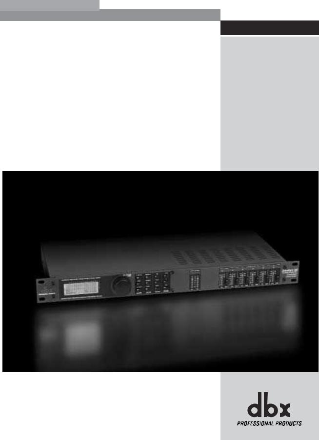
Complete Equalization & Loudspeaker Management System |
260 |
Featuring |
Custom Tunings |
User Manual |
IMPORTANT SAFETY INSTRUCTIONS
C A U T I O N |
RIS K O F ELECTRI C SHOCK |
D O NO T OPEN |
ATTENTION: RISQU E D E CHO C ELECTRIQU E - N E PA S OUVRIR |
WARNING: T O REDUC E TH E RIS K O F FIR E O R ELECTRIC
SHOC K D O NO T EXPOS E THI S EQUIPMEN T T O RAI N O R MOISTURE
The symbols shown above are internationally accepted symbols that warn of potential hazards with electrical products. The lightning flash with arrowpoint in an equilateral triangle means that there are dangerous voltages present within the unit. The exclamation point in an equilateral triangle indicates that it is necessary for the user to refer to the owner’s manual.
These symbols warn that there are no user serviceable parts inside the unit. Do not open the unit. Do not attempt to service the unit yourself. Refer all servicing to qualified personnel. Opening the chassis for any reason will void the manufacturer’s warranty. Do not get the unit wet. If liquid is spilled on the unit, shut it off immediately and take it to a dealer for service. Disconnect the unit during storms to prevent damage.
SAFETY INSTRUCTIONS
NOTICE FOR CUSTOMERS IF YOUR UNIT IS EQUIPPED WITH A POWER CORD.
WARNING: THIS APPLIANCE MUST BE EARTHED.
The cores in the mains lead are coloured in accordance with the following code:
GREEN andYELLOW - Earth BLUE - Neutral BROWN - Live
As colours of the cores in the mains lead of this appliance may not correspond with the coloured markings identifying the terminals in your plug, proceed as follows:
•The core which is coloured green and yellow must be connected to the terminal in the plug marked with the letter E, or with the earth symbol, or coloured green, or green and yellow.
•The core which is coloured blue must be connected to the terminal marked N or coloured black.
•The core which is coloured brown must be connected to the terminal marked L or coloured red.
This equipment may require the use of a different line cord, attachment plug, or both, depending on the available power source at installation. If the attachment plug needs to be changed, refer servicing to qualified service personnel who should refer to the table below. The green/yellow wire shall be connected directly to the units chassis.
CONDUCTOR |
WIRE COLOR |
||
|
|
Normal |
Alt |
L |
LIVE |
BROWN |
BLACK |
N |
NEUTRAL |
BLUE |
WHITE |
E |
EARTH GND |
GREEN/YEL |
GREEN |
WARNING: If the ground is defeated, certain fault conditions in the unit or in the system to which it is connected can result in full line voltage between chassis and earth ground. Severe injury or death can then result if the chassis and earth ground are touched simultaneously.
WARNING FOR YOUR PROTECTION
PLEASE READ THE FOLLOWING:
KEEP THESE INSTRUCTIONS
HEED ALL WARNINGS
FOLLOW ALL INSTRUCTIONS
DO NOT USE THIS APPARATUS NEAR WATER
CLEAN ONLY WITH A DRY CLOTH.
DO NOT BLOCK ANY OF THE VENTILATION OPENINGS. INSTALL IN ACCORDANCE WITH THE MANUFACTURER’S INSTRUCTIONS.
DO NOT INSTALL NEAR ANY HEAT SOURCES SUCH AS RADIATORS, HEAT REGISTERS, STOVES, OR OTHER APPARATUS (INCLUDING AMPLIFIERS) THAT PRODUCE HEAT.
ONLY USE ATTACHMENTS/ACCESSORIES SPECIFIED BY THE MANUFACTURER.
UNPLUG THIS APPARATUS DURING LIGHTNING STORMS OR WHEN UNUSED FOR LONG PERIODS OF TIME.
Do not defeat the safety purpose of the polarized or grounding-type plug. A polarized plug has two blades with one wider than the other. A grounding type plug has two blades and a third grounding prong. The wide blade or third prong are provided for your safety. If the provided plug does not fit your outlet, consult an electrician for replacement of the obsolete outlet.
Protect the power cord from being walked on or pinched particularly at plugs, convenience receptacles, and the point where they exit from the apparatus.
Use only with the cart stand, tripod bracket, or table specified by the manufacture, or sold with the apparatus. When a cart is used, use caution when moving the cart/apparatus combination to avoid injury from tip-over.
Refer all servicing to to qualified service personnel. Servicing is required when the apparatus has been damaged in any way, such as power-supply cord or plug is damaged, liquid has been spilled or objects have fallen into the apparatus, the apparatus has been exposed to rain or moisture, does not operate normally, or has been dropped.
POWER ON/OFF SWITCH: For products provided with a power switch, the power switch DOES NOT break the connection from the mains.
MAINS DISCONNECT: The plug shall remain readily operable. For rack-mount or installation where plug is not accessible, an all-pole mains switch with a contact separation of at least 3 mm in each pole shall be incorporated into the electrical installation of the rack or building.
FOR UNITS EQUIPPED WITH EXTERNALLY ACCESSIBLE FUSE RECEPTACLE: Replace fuse with same type and rating only.
MULTIPLE-INPUT VOLTAGE: This equipment may require the use of a different line cord, attachment plug, or both, depending on the available power source at installation. Connect this equipment only to the power source indicated on the equipment rear panel. To reduce the risk of fire or electric shock, refer servicing to qualified service personnel or equivalent.
This Equipment is intended for rack mount use only.

IMPORTANT SAFETY INSTRUCTIONS
ELECTROMAGNETIC
COMPATIBILITY
This unit conforms to the Product Specifications noted on the Declaration of Conformity. Operation is subject to the following two conditions:
•this device may not cause harmful interference, and
•this device must accept any interference received, including interference that may cause undesired operation.
Operation of this unit within significant electromagnetic fields should be avoided.
•use only shielded interconnecting cables.
U.K. MAINS PLUG WARNING
A molded mains plug that has been cut off from the cord is unsafe. Discard the mains plug at a suitable disposal facility. NEVER UNDER
ANY CIRCUMSTANCES SHOULD YOU INSERT A DAMAGED OR CUT MAINS PLUG INTO A 13 AMP POWER SOCKET. Do not use the mains plug without the fuse cover in place. Replacement fuse covers can be obtained from your local retailer. Replacement fuses are 13 amps and MUST be ASTA approved to BS1362.
DECLARATION OF
CONFORMITY
Manufacturer’s Name: dbx Professional Products Manufacturer’s Address: 8760 S. Sandy Parkway
Sandy, Utah 84070, USA
declares that the product:
Product name: |
dbx 260 |
Note: |
Product name may be suffixed by the |
|
EU. |
Product option: None
conforms to the following Product Specifications:
Safety: IEC 60065 (1998)
EMC: EN 55013 (1990)
EN 55020 (1991)
Supplementary Information:
The product herewith complies with the requirements of the Low Voltage Directive 72/23/EEC and the EMC Directive 89/336/EEC as amended by Directive 93/68/EEC.
Vice-President of Engineering
8760 S. Sandy Parkway
Sandy, Utah 84070, USA
Date: September 19,2002
European Contact:
Your local dbx Sales and Service Office or
Harman Music Group 8760 South Sandy Parkway Sandy, Utah 84070 USA Ph: (801) 566-8800
Fax: (801) 568-7583

|
DriveRack™ |
|
|
|
Table of Contents |
|
Introduction |
|
4.8 |
Post-Crossover PEQ........................................ |
33 |
||
0.1 |
Defining the 260 DriveRack ............................ |
ii |
4.9 |
Compressor/Limiter ........................................ |
34 |
|
0.2 |
Service Contact Info........................................ |
iii |
4.10 |
Alignment Delay........................................... |
37 |
|
0.3 |
Warranty........................................................... |
iv |
4.11 |
Input Routing................................................ |
37 |
|
|
|
|
4.12 |
Output ........................................................... |
38 |
|
Section 1 - Getting Started
1.1 |
Rear Panel Connections ................................... |
2 |
1.2 |
Front Panel ....................................................... |
2 |
1.3 |
Quick Start ........................................................ |
4 |
Section 2 - Editing Functions |
|
|
2.1 |
Basic Navigation Modes................................. |
14 |
2.2 |
Effect Button Array Overview ....................... |
14 |
2.3 |
Navigating the Pre-EQ Section ...................... |
15 |
2.4 |
Navigating the Crossover Section.................. |
15 |
2.5 |
Navigating the Other Section ........................ |
16 |
2.6 |
Navigating the Dynamics Section.................. |
16 |
2.7 |
Navigating the Delay Section ........................ |
17 |
2.8 |
Navigating the Utility/Meters Section............ |
17 |
2.9 |
Navigating the Wizard Section ...................... |
18 |
2.10 Navigating the I/O Section .......................... |
18 |
|
Section 5 - Utilities/Meters |
|
5.1.1 LCD Contrast/Auto EQ Plot ........................ |
40 |
5.1.2 PUP Program/Mute...................................... |
40 |
5.1.3 ZC Setup ...................................................... |
41 |
5.1.4 Security......................................................... |
42 |
5.1.5 Program List/Program change .................... |
45 |
5.1.6 Output Jumper switches ............................. |
46 |
5.2.1 Meters........................................................... |
47 |
Section 6 - Remote Control |
|
6.1.1 PC GUI Installation...................................... |
50 |
System Requirements ........................................... |
50 |
Install ..................................................................... |
50 |
Basic Operation .................................................... |
50 |
Cable specs ........................................................... |
52 |
6.2.1 ZC-Zone Controllers.................................... |
53 |
Section 3 - Configuration Functions
3.1 |
Program Definition......................................... |
20 |
3.2 |
Navigating Factory Programs......................... |
20 |
3.3 |
Editing Factory Programs............................... |
21 |
3.4 |
Saving Factory Program Changes.................. |
22 |
3.5 |
Creating a User Configuration ....................... |
23 |
3.6 |
Saving Configuration Changes....................... |
26 |
Section 4 - Detailed Parameters |
||
4.1 |
Pre-Crossover EQ (31 Band Graphic) or |
|
|
(9-Band Parametric) ........................................ |
28 |
4.2 |
Feedback Eliminator (AFS) ............................ |
29 |
4.3 |
Subharmonic Synthesizer............................... |
30 |
4.4 |
Noise Gate ...................................................... |
31 |
4.5 |
Automatic Gain Control (AGC) ..................... |
32 |
4.6 |
Notch Filters.................................................... |
33 |
4.7 |
Crossover ........................................................ |
33 |
Section 7 - Application Guide
7.1 |
Mono 4-Way w/ 2 Aux Zones ....................... |
58 |
|
7.2 |
Stereo Tri-Amp ............................................... |
59 |
|
7.3 |
Stereo w/ 4 Aux Zones.................................. |
60 |
|
7.4 |
Stereo Bi-Amp w/ Dual Delays..................... |
61 |
|
Appendix |
|
||
A.1 |
Factory Reset .................................................. |
64 |
|
A.2 |
Power up Quick Key Options ...................... |
64 |
|
A.3 |
Specifications.................................................. |
65 |
|
A.4 |
Auto EQ Optimization................................... |
66 |
|
A.5 |
Crossover Diagrams....................................... |
67 |
|
A.6 |
Prog List/Speaker Tunings/ |
|
|
|
|
Power Amp Tunings...................................... |
68 |
A.7 |
Block Diagram ............................................... |
69 |
|
A.8 |
Input and Output Section Diagrams ............ |
70 |
|
A.9 |
Gain Level Jumpers ....................................... |
71 |
|
A.10 System Setup and Gain Structure ............... |
71 |
||
®
Table of Contents DriveRack™ User Manual
DriveRack™
INTRODUCTION
INTRO
CUSTOMER SERVICE INFO
Defining the
DriveRack
WARRANTY INFO
®

|
Introduction |
DriveRack |
™ |
|
|
||
|
|
|
INTRODUCTION |
Congratulations on your purchase of the dbx® DriveRack™ 260 Complete Equalization and |
|
Loudspeaker Management System! For over 30 years, dbx has been the industry leader in |
||
|
||
|
dynamics processing. With the DriveRack 260, dbx Professional Products has redefined the stan- |
|
|
dard by which all other loudspeaker management processors will be compared. |
|
|
The DriveRack 260 continues the legacy of DriveRack™ family. The DriveRack 260 was designed |
|
|
with the purpose and vision of providing state-of-the-art signal processing, while utilizing a sim- |
|
|
ple and intuitive user interface. For more information, please visit: www.driverack.com or |
|
|
www.dbxpro.com. |
|
|
This manual will be your guide to understanding the full functionality of the powerful |
|
|
DriveRack 260 . By combining the different components, the configuration possibilities are lim- |
|
|
itless. After you have become familiar with the unit, we encourage you to experiment and find |
|
|
the most effective and efficient way to run your system by utilizing the powerful processing of |
|
|
the DriveRack 260. |
0.1 Defining the 260 DriveRack System
The dbx 260 DriveRack is the most effective way to manage all aspects of post mixer processing and signal routing. The 260 DriveRack essentially becomes the only device that you will need between the mixer and the power amps. The following are just some of the features of the 260 and 260 DriveRack™ units.
260 DriveRack™ features:
•Advanced Feedback Suppression™
•2.7 Seconds of Alignment and Zone Delay
•RS-232 PC GUI control
•Classic dbx® Compression and Limiting
•Graphic and Parametric EQ
•Independent Input and Output Processing
•Auto-EQ Function
•Full Bandpass, Crossover, and Routing Configurations
•Auto Gain Control
•Pink Noise Generator and full-time RTA
•Setup Wizard with JBL® and Crown® Components
•Security Lockout
•Wall Panel Control Inputs
®
ii |
DriveRack™ User Manual |
|
|
DriveRack™ |
Introduction |
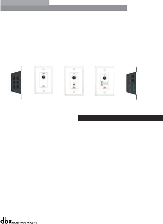
In addition to the amazing menu of processors available, the 260 also affords you the luxury of utilizing dbx Zone-Controller series wall-mounted control panels that will allow you to remotely control various parameters of the 260. The ZC-1 offers remote programmable Volume control to any installation using the DriveRack™ 260. The ZC-2 provides programmable Volume and Mute control. Both the ZC-1 and ZC-2 can be programmed for up to six outputs of the DriveRack™ 260. The ZC-3 allows Program Selection on the 260. The ZC-4 also offers Program Selection via Contact Closure inputs for Room Combining applications. Up to six Zone Controllers can be used with a single DriveRack™ 260, and can either be wired in series or parallel. The ZC-BOB was created to accommodate “home-run” or parallel wiring to the unit. With a maximum length of 5,000 ft., the Zone Controllers offer a simple way to create a simple yet elegant solution to many installation applications.
ZC-BOB |
ZC-1 |
ZC-2 |
ZC-3 |
ZC-4 |
|
|
|
|
0.2 Service Contact Info
If you require technical support, contact dbx Customer Service. Be prepared to accurately describe the problem. Know the serial number of your unit - this is printed on a sticker attached to the top panel. If you have not already taken the time to fill out your warranty registration card and send it in, please do so now.
Before you return a product to the factory for service, we recommend you refer to the manual. Make sure you have correctly followed installation steps and operation procedures. If you are still unable to solve a problem, contact our Customer Service Department at (801) 568-7660 for consultation. If you need to return a product to the factory for service, you MUST contact Customer Service to obtain a Return Authorization Number.
No returned products will be accepted at the factory without a Return Authorization Number.
Please refer to the Warranty information on the following page, which extends to the first enduser. After expiration of the warranty, a reasonable charge will be made for parts, labor, and packing if you choose to use the factory service facility. In all cases, you are responsible for transportation charges to the factory. dbx will pay return shipping if the unit is still under warranty.
Use the original packing material if it is available. Mark the package with the name of the shipper and with these words in red: DELICATE INSTRUMENT, FRAGILE! Insure the package properly. Ship prepaid, not collect. Do not ship parcel post.
®
DriveRack™ User Manual |
iii |
|
|

|
Introduction |
DriveRack |
™ |
|
|
||
|
|
|
0.3 Warranty
This warranty is valid only for the original purchaser and only in the United States.
1.The warranty registration card that accompanies this product must be mailed within 30 days after purchase date to validate this warranty. Proof-of-purchase is considered to be the burden of the consumer.
2.dbx warrants this product, when bought and used solely within the U.S., to be free from defects in materials and workmanship under normal use and service.
3.dbx liability under this warranty is limited to repairing or, at our discretion, replacing defective materials that show evidence of defect, provided the product is returned to dbx WITH RETURN AUTHORIZATION from the factory, where all parts and labor will be covered up to a period of two years. A Return Authorization number must be obtained from dbx by telephone. The company shall not be liable for any consequential damage as a result of the product's use in any circuit or assembly.
4.dbx reserves the right to make changes in design or make additions to or improvements upon this product without incurring any obligation to install the same additions or improvements on products previously manufactured.
5.The foregoing is in lieu of all other warranties, expressed or implied, and dbx neither assumes nor authorizes any person to assume on its behalf any obligation or liability in connection with the sale of this product. In no event shall dbx or its dealers be liable for special or consequential damages or from any delay in the performance of this warranty due to causes beyond their control.
®
iv |
DriveRack™ User Manual |
|
|
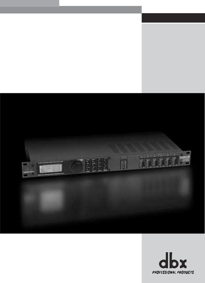
DriveRack™ |
Section 1 |
Getting Started
®
Section 1 |
Getting Started |
DriveRack |
™ |
|
|||
|
|
|
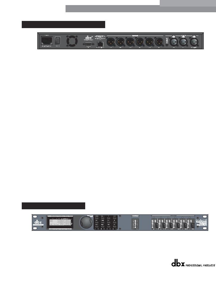
1.1 Rear Panel Connections
IEC Power Cord Receptacle
The DriveRack 260 comes with a power supply that will accept voltages ranging from 100V120V at frequencies from 50Hz-60Hz. An IEC cord is included. EU version accepts 220V-240V at frequencies from 50Hz-60Hz.
Power Switch
The Power Switch turns the DriveRack 260 on and off. Note: dbx Professional Products recommends that power amplifiers connected to the DriveRack 260, should be powered down prior to cycling the power on the DriveRack 260.
PC Connection
This DB-9 type connection is used to send and receive information to and from the GUI interface.
RS485 Zone Control Input (RJ-45 connector type)
This input connection is used to send information and power to the ZC wall controllers.
Outputs 1-6
The output section of the DriveRack 260 offers six electronically balanced XLR connectors.
Inputs 1-2
The input section of the DriveRack 260 offers two electronically balanced XLR connectors.
Ground Lift Switch
The ground lift switch lifts the pin 1 chassis ground of both input XLR connectors.
RTA Input Jack
This balanced XLR input is used for the connection of an RTA microphone, which allows the user to “Pink” and optimize the EQ settings of any room through the use of the Auto EQ in the Wizard setup assistant.
1.2 Front Panel
®
2 |
DriveRack™ User Manual |
|
|
DriveRack™ |
Getting Started |
Section 1 |
LCD Display
The backlit LCD display of the DriveRack 260 provides the user with all of the vital processing information of the DriveRack 260 including: signal routing, effect block editing and Wizard Setup functions. The display will also notify the user if any internal clipping is taking place within the unit by displaying “CLIP” in the display.
Data Wheel
The Data wheel of the DriveRack 260 is used to scroll through the program menu, load programs, select parameters and edit parameter values.
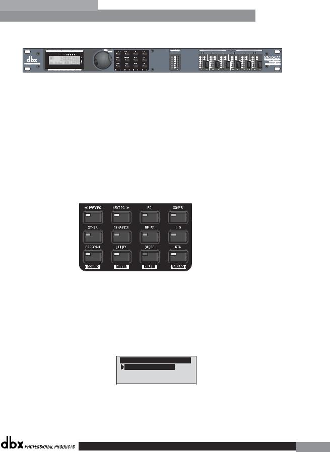
Function Buttons
The function buttons of the DriveRack 260 allow direct access to all editing and navigating functions of the DriveRack 260. The functions of the aforementioned buttons are as follows:
<PREV PG> - is used to navigate back through the various pages of any module block. <NEXT PG> - is used to navigate forward through the various pages of any module block. <EQ> - is used to move to the EQ modules. Successive presses will move you through the
EQ modules in the input section and through EQ modules located in the output section. <XOVER> - is used to move to the Crossover module.
<OTHER> - This button is used to move to the insert module section module which can include modules such as: Notch Filters, Subharmonic Synthesizer and the Advanced Feedback Suppression (AFS) modules.
<DYNAMICS> - is used to move to the Compressor, Compressor, Gate, Auto Gain Control (AGC), or Limiter modules.
<DELAY> - is used to move to the Delay modules.
<I/O> - is used to move to select each one of the 2 input and 6 output modules. <PROGRAM> (CONFIG)- is used to enter program mode. When pressed and held, the 260
will enter configuration mode.
<UTILITY> (METER)- is used to access the the Utility menu. When pressed and held, the 260 will enter METER mode.
<STORE> (DELETE)- is used to store any program changes. When pressed and held, the 260 will enter the PROGRAM DELETE module.
<RTA> (WIZARD)- is used to enter the RTA module. When pressed and held, the 260 will enter the Wizard section which includes: SYSTEM SETUP, AFS and AUTO EQ WIZARD.
Input Meters
The DriveRack 260 provides the user with two independent, six segment Lightpipe™ input meters that range from -30 to +22 dBu. These meters monitor the signal level right after the input module.
Threshold Meters
The threshold meters indicate that the threshold level has been exceeded within the Limiter and Auto Gain Control sections, and gain reduction may be taking place within the specific output channel.
Output Mutes
The six output mute buttons are used for independently muting each output on all six outputs of the DriveRack 260.
®
DriveRack™ User Manual |
3 |
|
|
Section 1 |
Getting Started |
DriveRack |
™ |
|
|||
|
|
|
Output Meters
The DriveRack 260 provides the user with six independent six-segment Lightpipe™ output meters that range from -30 to +22 dBu.
1.3 Quick Start
For those of you that wish to jump right in, the following information has been provided to act as a quick start guide for optimizing performance of the DriveRack 260.
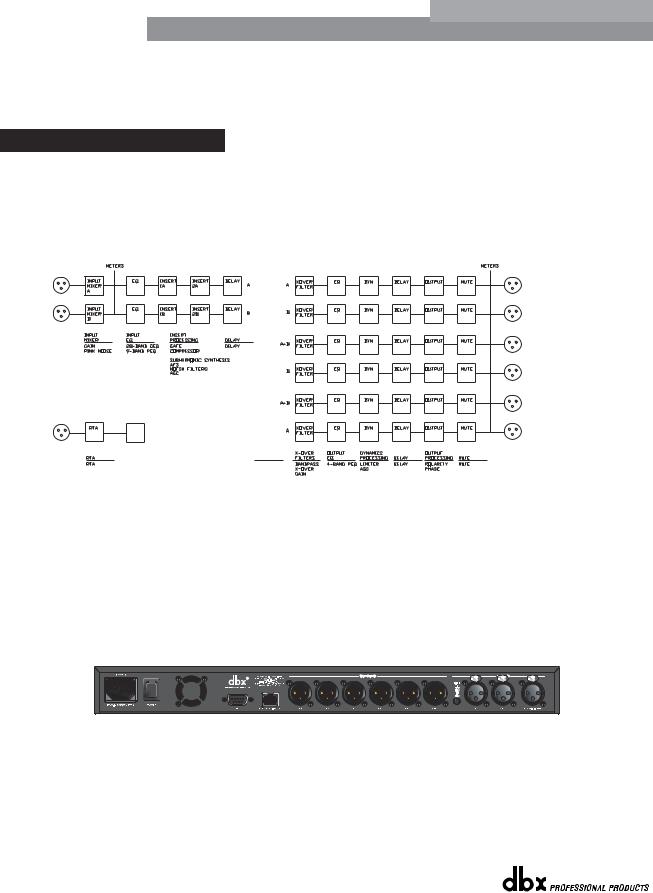
Signal Path Block Diagram
The following diagram shows the logical and intuitive signal path of the input, effect modules, and output of the DriveRack 260.
260 Signal Path
WIRE
RTA
MIXER
RTA
ROUTING
A
B
A+B
Connections
•When setting up the DriveRack 260, make connections as follows:
•Always make connections prior to applying power to the unit.
•Connect the output from the sending device (mixer) to either of the two XLR inputs connectors shown below.
•Make output connections from any one of the six output XLR connectors shown below to the input of the selected power amps.
•Connect the selected RTA microphone to the RTA XLR input.
•IMPORTANT- It is recommended that the power amps are turned off prior to cycling power to the Driverack
260. Always make sure that your power amps are the last item turned on and the first turned off.
Once all of the connections have been made and the unit is powered up, you can navigate through the entire signal path of the DriveRack 260 from the front panel of the unit. The display provides you with a clear and concise overview of each aspect
®
4 |
DriveRack™ User Manual |
|
|
DriveRack™ |
Getting Started |
Section 1 |
of the signal path from the input to the output section.
The features of the front panel of the DriveRack 260 are as follows from left to right. LCD Display- All operational information of the 260 DriveRack is displayed here. The display will also notify the user if any internal clipping is taking place within the unit. The following message will appear: CLIP. Data Wheel - The data wheel is used to scroll through the program menu of the 260 DriveRack. The Data Wheel is also used to perform editing functions to effects and utility menu features. Button Array - Operational editing is done using this 12 button array. A complete description of each button’s functionality is listed below. Input meters- These two 6-segment LED meters monitor the input level of the 260 DriveRack directly after the input mixer. Output mutes - These six mute buttons are used to mute the output signal of the 260 DriveRack. Output meters - These six 6-segment meters monitor the output levels of the 260 DriveRack directly after the output gain stage. Threshold meters - These six 1-segment meters show that threshold level of the output dynamics has been exceeded.
260 DriveRack Wizard
Now that you have made all of your audio connections and have made yourself familiar with the front-panel navigation of the unit, you can easily optimize your system through the use of the 260 DriveRack Wizard. This feature of the 260 DriveRack allows for quick and accurate venue setups. The menu section of the Wizard offers System setup, Auto EQ and AFS (Advanced Feedback Suppression). The following will walk you through your venue setup.
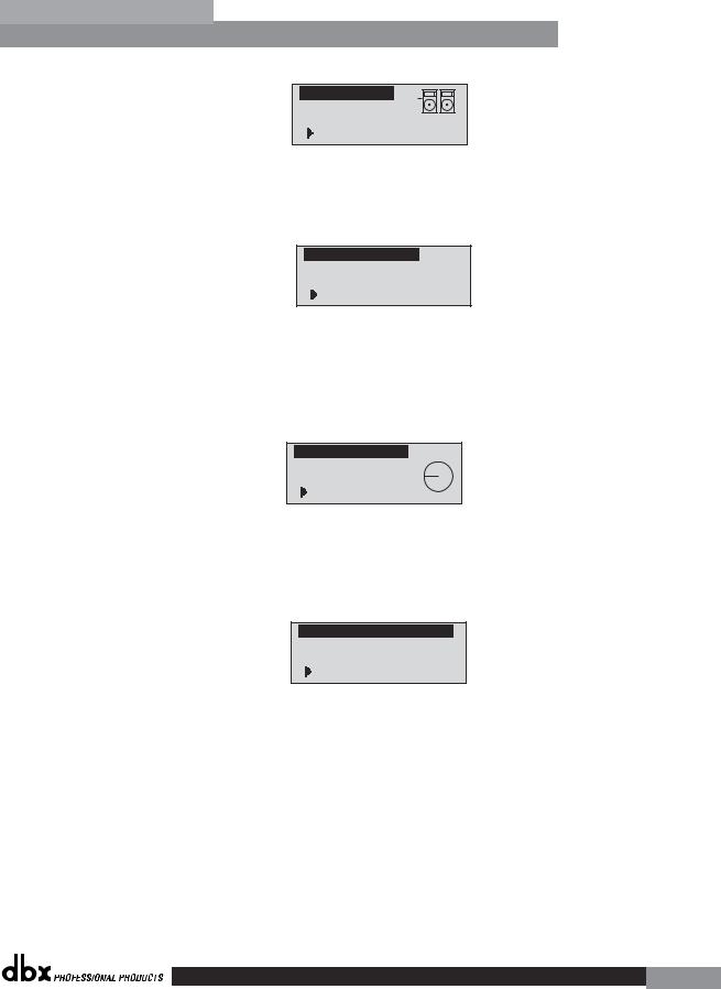
•From program mode, press and hold the <RTA> /Wizard button and the display will appear as follows:
DriveRack 260 Wizard
System Setup
Auto EQ Wizard
AFS Wizard
®
5
Section 1 |
Getting Started |
DriveRack |
™ |
|
|||
|
|
|
System Setup
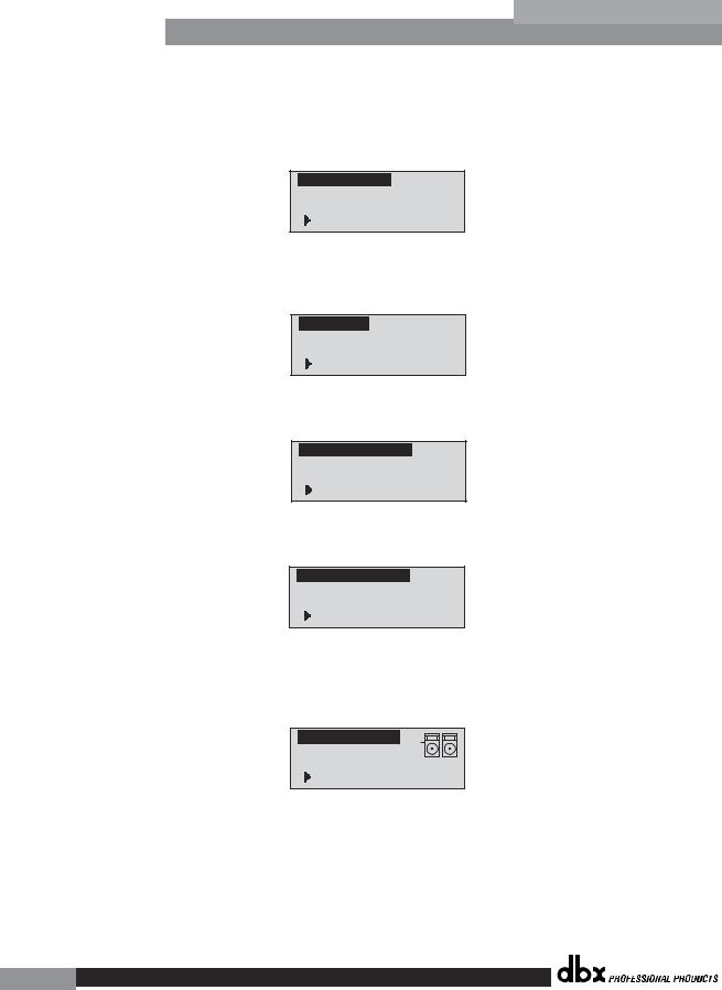
•The arrow will indicate the selected Wizard setup. To select any one of the three options, rotate the <DATA> wheel. If you are performing the System setup, press either the <NEXT PG> button or the <DATA> wheel and the display will appear as follows:
Input Setup
Select Input as MONO or STEREO.
>STEREO
•Simply rotate the <DATA> wheel to select either a Mono or Stereo input configuration. Once you have selected your input option, press the <NEXT PG> button and the display will appear as follows:
EQ Setup
Select EQ as GEQ or PEQ
>PEQ
•Simply rotate the <DATA> wheel to select either a Graphic or Parametric EQ. Once you have selected your EQ option, press the <NEXT PG> button and the display will appear as follows:
Insert 1 Setup Select Insert 1 effect.
>Compressor
•Rotate the <Data> wheel to select any one of the numerous Insert modules available. Once you have selected your Insert 1 module option, press the <NEXT PG> button and the display will appear as follows:
Insert 2 Setup Select Insert 2 effect.
>AFS
•Rotate the <Data> wheel to select any one of the numerous Insert modules available. Once you have selected your Insert 1 module option, press the <NEXT PG> button and the display will appear as follows:
Main Speaker
Select Main PA
JBL SRX
>SR4702X Passive
•Rotate the <Data> wheel to select any one of the numerous custom-tuned MAIN speaker options available. If the speaker being used is not specified in the menu, select CUSTOM. Once you have selected your Main speaker option, press the <NEXT PG> button and the display will appear as follows:
®
6
DriveRack™ |
Getting Started |
Section 1 |
Sub Speaker
Select Sub PA
>None
•Rotate the <Data> wheel to select any one of the numerous custom-tuned SUB speaker options available. Once you have selected your SUB speaker option, press the <NEXT PG> button and the display will appear as follows:
High Amplifier
Select an amplifier
>Crwn MacroTech 1202
•You are now prompted to select a power amp by rotating the <DATA> wheel to select any one of the numerous custom-tuned Amplifier options available. Note that the top line of the display will either read High, Mid or Low depending on your selected speaker setup selections. Once you have selected your Amp tuning option (depending on the amp type), you will select the specified amplifier sensitivity setting if applicable.
High Amp Level Adjust level same as your amp >25
•Rotate the <DATA> wheel to select the amplifier manufacturer’s specified amplifier sensitivity setting. Once set, press the <NEXT PG> button, and you will now be given the option of optimizing your amp levels with the 260 DriveRack for . The page will appear something like this:
Low Amp Bridging Select
same as your amp >Normal
•You will now rotate the <DATA> wheel to match the same setting as your amplifier of choice. Note that based on your amp selection, the 260 DriveRack will initially display the recommended setting of that particular amp for obtaining maximum headroom. This is done to match unity gain from the 260 DriveRack and your amplifier. Note that if Sub Speakers are included in the speaker selection, you will be asked if the sub woofer is bridged or mono. For more information regarding Amplifier gain settings, please refer to the System Setup and Gain Structure information located in the appendix section.
Note that you will perform the previous Amplifier settings for Mid and
Low if your application requires Mid and Low amplifiers.
®
7
Section 1 |
Getting Started |
DriveRack |
™ |
|
|||
|
|
|
•Once you have completed your amp level settings, you will press the <NEXT PG> button, where you will be asked to select a bridged or normal setting fro your low amp (if used). The display will appear as follows:
•Once have made a bridged or mono selection, press the <NEXT PG> where the unit will prompt <DATA> wheel to load your new settings. If you do not wish to load the settings either press the <PROGRAM> button or use the <PREV PG> button to re-edit your settings, By using your selections, the DriveRack™ will automatically generate a new program and speaker selection which are used to choose the correct crossover type, parameters, speaker compensation EQ and delay are also adjusted by the speaker selection. Amplifier parameters are used to set the limiters to stop amplifier clipping and balance out the crossover levels. You may find that you want to re-adjust the crossover levels based on your taste and type of music.
Auto EQ WIZARD
•Once you have custom-tailored your system setup, you can now proceed to EQ your system. The Auto EQ Wizard automatically adjusts the response of the system by producing pink noise and adjusting the Graphic EQ until the RTA matches a selected response. From the 260 DriveRack Wizard menu, rotate the <DATA> wheel until the display appears as follows:
DriveRack 260 Wizard
System Setup
Auto EQ Wizard
AFS WIZARD
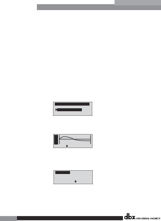
•Either press the <NEXT PG> button or rotate the <DATA> wheel and the display will read:
A |
|
|
u E |
|
|
t Q |
|
|
o |
|
|
RESPONSE |
C PRECISION |
LOW |
•You can now select any one of the several different Frequency responses for the Auto EQ. The options are: Flat (0), and Response A-D, and Low, Medium and High Precision. Once you have selected your desired EQ Frequency response, press the <NEXT PG> button and the display will appear as follows:
Auto EQ : Pink Noise
Mic Level 

Turn Up Level
Pink Level > 18dB
•You will now proceed to “Pink” the room by adjusting the Pink level. The range of bar graph is -30dBu to +20dBu. Connect an RTA-specific microphone to the rear-panel RTA mic input.
®
8
DriveRack™ |
Getting Started |
Section 1 |
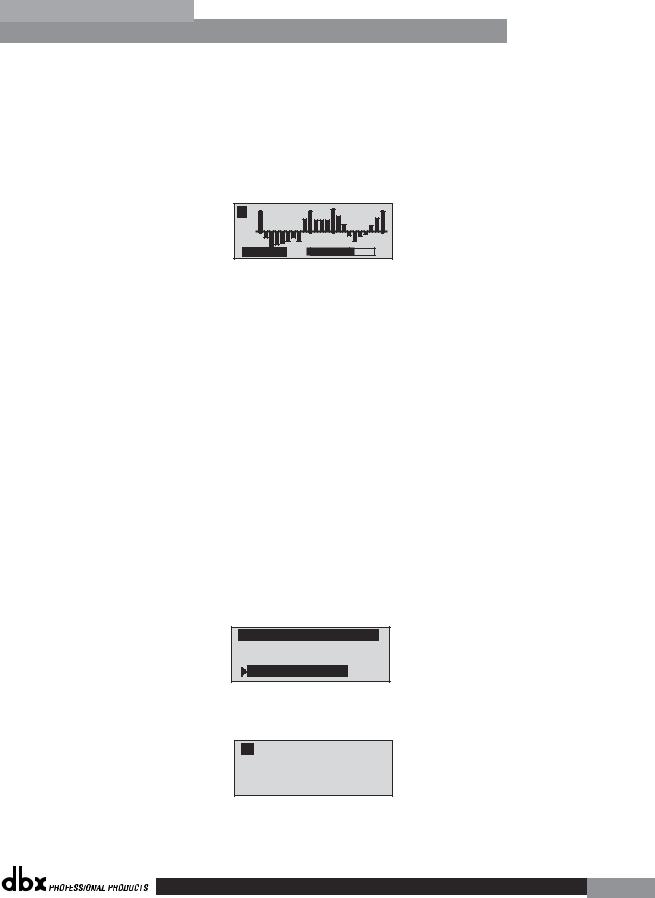
to. Be certain to raise the pink noise level to the level to be used during the performance. Once the Pink level has been adjusted to the desired volume. The mic level indicator will register the signal level. Press the <NEXT PG> button and the Auto EQ sequence will begin. The display will either show the graphic EQ or the RTA. Rotating the <DATA> wheel clockwise and counter clockwise will toggle between the two modes. You can also select either mode to default to in the Utility menu. Regardless, the display will appear something like this:
A B |
Auto EQ
•At this point, the 260 DriveRack will automatically EQ the room. If you are using independent left and right graphic EQs, you will auto EQ each side independently. If you are using a stereo-linked EQ, both sides will be EQ’d simultaneously. Auto EQ can be aborted at any point in the process by pressing the <NEXT PG> button. Upon completion of the Auto EQ Wizard, you can return to program mode by releasing the <RTA Input> button and pressing the <PROGRAM> button.
For more information regarding the Auto EQ section, please refer to the Auto EQ Optimization Tips information located in the Appendix section.
AFS
•The 260 DriveRack also offers its exclusive AFS (Advanced Feedback Suppression) module which is located within the INSERT module section of select or user-created configurations. This unique feature now makes unwanted feedback in a PA system a thing of the past. The AFS Wizard will lead you through the setup of of the fixed filters of the AFS module. The fixed filter mode is designed to place notch filters as you introduce feedback by opening up your mics and slowly increasing the gain. Because the fixed mode is sensitive, it is important not to present an external music source such as CD player or other audio signal into the system. From the Wizard menu, rotate the <DATA> wheel until the display appears as follows:
DriveRack 260 Wizard
System Setup
Auto EQ Wizard
AFS Wizard
• Press the <NEXT PG> button and the display will read:
A B
Please turn down the mixer gain. Press
NEXT PG when done.
• Once the gain level of the mixer has been turned down, press the <NEXT PG> but-
®
9
Section 1 |
Getting Started |
DriveRack |
™ |
|
|||
|
|
|
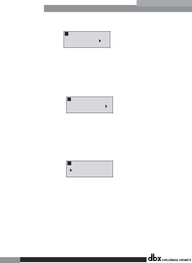
ton and the display will read:
A B F F F F F F L L L L L L
Select total number of AFS filters. 12
•You will now use the <DATA> wheel to select the number of fixed filters. This will range from values 0-12. The total number of filters will stay at 12, and the number of live filters will be = Total Num Filters – Num Fixed. Live and Fixed filter types differ in that FIXED mode filters are automatically assigned to a frequency creating feedback, thus remaining at that frequency until cleared by the user. In LIVE mode, live filters automatically detect and remove feedback frequencies in the presence of audio (music or speech). When all of the live filters have been used, they begin to round robin. Essentially this means that the first filter set is replaced where a new feedback is detected and notched out. This mode is useful because feedback frequencies may change as the microphone is moved, and/or as the characteristics of the venue change.
A B F F F F F F L L L L L L
Select number
of fixed filters. 6
•At this page, you will now select the number of fixed filter. Once the desired fixed number of filters has been selected, press the <NEXT PG> button and the display will read:
The Fixed/Live filter usage will be indicated at the bottom of each page of the feedback elimination effect. ‘F’ indicates an available fixed filter, and ‘L’ indicates an available live filter. A blocked out F or L indicates a filter that is set, or in use. Once the desired number has been selected, press the <NEXT PG> and the display will read:
A B
Select fixed type
>Speech
•These types pertain to the Q, sensitivity, and algorithm type. The filter is established by using the formula: Q= Freq divided by Bandwidth. This means that a higher Q will produce a filter that is more narrow. Values are: Speech (Bandwidth = 1/5 octave and Q=7.25) Music Low (Narrow notch filter, Bandwidth = 1/10 octave and Q=14.5), Music Medium (Very Narrow notch filter, Bandwidth = 1/20 octave and Q=29) Music High (Ultra Narrow notch filter, Bandwidth = 1/80 octave and Q=116). To guarantee that feedback is suppressed at lower frequencies, the AFS may place wider notch filters at these lower frequencies (below 700 Hz). Once the desired fixed type has been selected, press the <NEXT PG> button and the display will read:
®
10
DriveRack™ |
|
|
Getting Started |
Section 1 |
|
|
|
|
|
|
|
|
|
A |
B F F F F F F L L L L L L |
|
|
|
|
Slowly Increase the |
|
|
|
|
|
mixer gain to |
|
|
|
|
|
desired level. |
|
|
|
|
|
|
|
|
|
•You are now prompted to raise the output gain of the mixer to the level of the performance. At this point, mics should be open (on) and you should slowly increase the mixer gain. Once the desired level has been set and all of the fixed filters have been assigned, the unit will automatically move you to the page that indicates the fixed filter setup has been completed. If you have reached the performance level setting and all of the fixed filters have not been used, you may want to return
to the page that selects the number of fixed filters and re-adjust the number of fixed in order to provide you with additional live filters. Regardless, once you have completed the setup, the display will read:
A B F F F F F F L L L L L L
Fixed filter setup done for Channel A. In LIVE mode.
•To return to program mode, simply press the <PROGRAM> or <NEXT PG> button. For more information regarding feedback elimination, please see the AFS parameters of the Detailed parameters section.
®
11

Section 1 |
Getting Started |
DriveRack |
™ |
|
|||
|
|
|
®
12
DriveRack™ |
Section 2 |
|
Editing Functions |
|
EDITING |
|
FUNCTIONS |
®
Section 2 |
Editing Functions |
DriveRack |
™ |
|
|||
|
|
|
Editing
Functions
2.1 Basic Navigation Modes
Navigational aspects of the 260 DriveRack is simple and as follows. 1. FX buttons - This array of 12 FX buttons is your primary mode of directly accessing any effect module. 2. NEXTPG & PREVPG page buttons - Successive presses of the NEXTPG or PREVPG page buttons will move the user from one page to the next in an effect block. 3. Data Wheel - The Data Wheel is used to move through the program menu of the 260 DriveRack. The Data wheel is also used to change the values of the selected parameter by simply rotating the wheel. Pressing the Data wheel will toggle between the available parameters on any selected page of the currently selected effect module.
2.2 Effect Button Array Overview
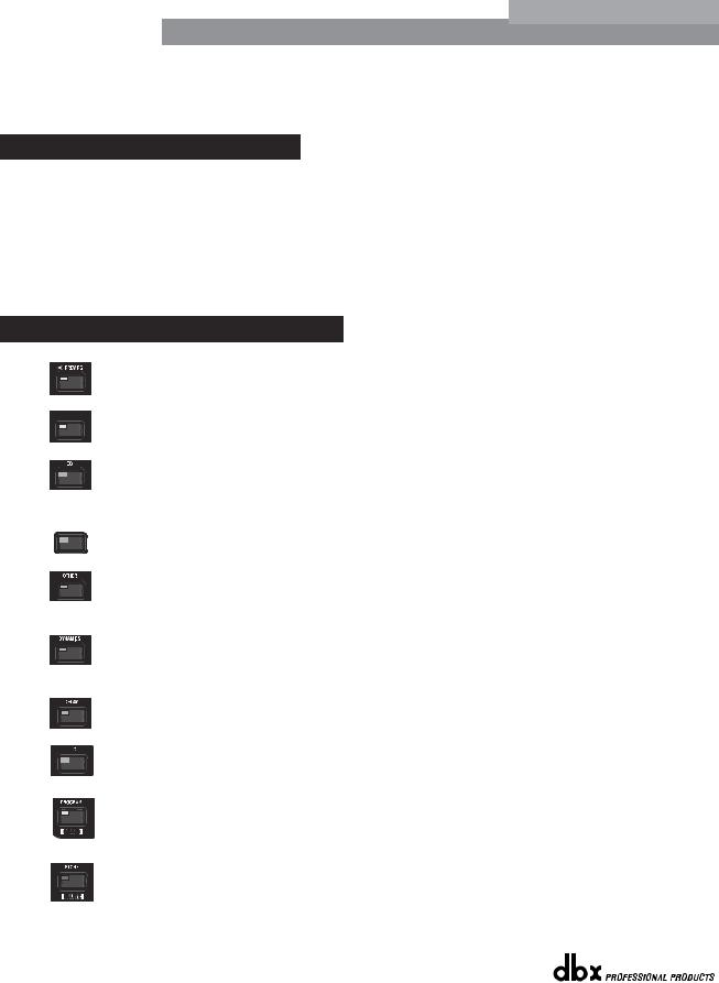
PREVIOUS PAGE - Moves to the previous page in the currently selected effect menu.
 NEXT PAGE - Moves to the next page in the currently selected effect menu.
EQ - Selects the EQ effect menu. This is the EQ section located prior to the crossover section. Successive presses will rotate through the various precrossover 28 band EQ and Post-xover PEQ section modules.
 XOVER - Selects the Crossover section.
OTHER - This button is used to move to the module insert section module which includes the Notch filter, Subharmonic Synthesizer, AFS (Advanced Feedback Suppression) and Wire (no parameters) modules.
DYNAMICS - Selects the Dynamics effect sections.
Successive presses will move from the Compressor, Gate and AGC (pre-xover) to the AGC and Limiter (post-xover).
DELAY - Selects the Alignment Delay effect module. successive presses will rotate through the Pre and post Delay modules.
I/O - Selects the input and output parameter editing section for all inputs and outputs. Successive presses will move through each input and output.
PROGRAM (Config) - This button is used to enter the Program screen from any sub section within the unit when pressed. When pressed and held, you will enter Config mode.
UTILITY(Meter) - Selects the Utility menu of the 260 DriveRack. When pressed and held, the 260 will enter METER mode.
®
14 |
DriveRack™ User Manual |
|
|
DriveRack™ |
Editing Functions |
Section 2 |
STORE(Delete) - The store button is used to store program edits.When pressed and held, the 260 will enter the PROGRAM DELETE module.
RTA (Wizard) - This enters the RTA mode, or when held, enters the 260
DriveRack Wizard setup menu which includes: System Setup, Auto EQ setup and
AFS Wizard.
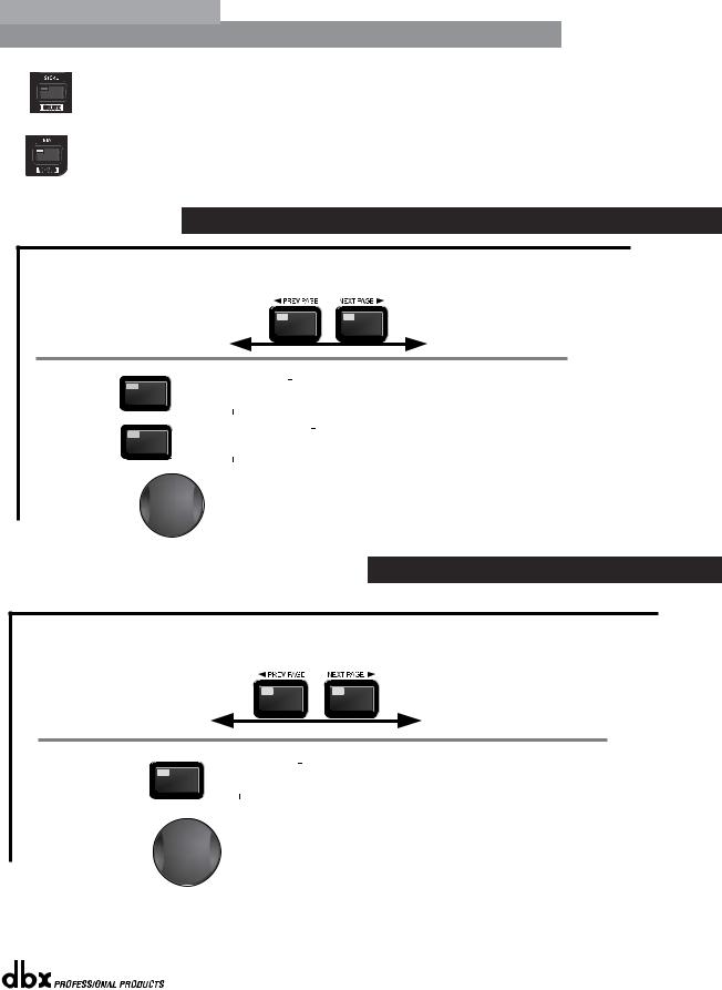
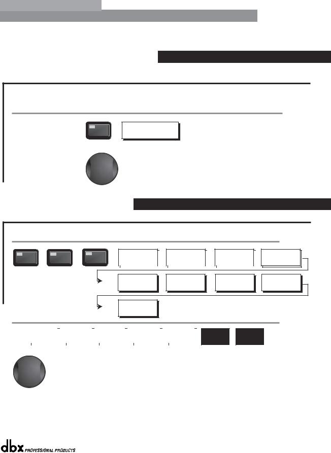
2.3 Navigating the EQ Section (28-GEQ and PEQ)
To edit the parameters of the EQs used in a selected program, simply use the following procedure. From program mode, press the EQ button to reach the EQ module to be edited. Successive presses of the EQ button will move through each channel.
Navigate through the Pages of the selected EQ section by depressing "Next Page" or "Prev Page" successively until arriving at the desired Page.
EQ
The EQ button toggles through
the EQs used in
EQ
each channel of
the selected program
menu.
GEQ
or
PEQ
|
GEQ On/Off |
|
|
Freq- 31.5Hz-18kHz |
|
|||
|
|
|
|
|||||
|
Flatten/Restore |
|
|
Gain |
-12dB to12dB |
|
||
|
|
|
|
|
|
|
|
|
|
|
|
|
|
|
|
|
|
|
PEQ On/Off |
|
|
|
|
|
B1 Freq- 20Hz-20kHz |
|
|
Flatten/Restore |
|
|
|
|
|
Gain -12dB to12dB |
|
|
Bell,HSelf, LShelf, LHShelf, |
|
|
Q .20 to 16.0 |
||||
|
|
|
|
|
|
|
|
|
GEQ/PEQ
|
B2 Freq- 20Hz-20kHz |
|
|
B2 Freq- 20Hz-20kHz |
|
... |
|
|
|
|
|||
|
Gain -12dB to12dB |
|
|
Gain -12dB to12dB |
|
|
|
Q .20 to 16.0 |
|
|
Q .20 to 16.0 |
|
|
|
|
|
|
|
|
|
Successive presses of the Data wheel will select effect parameters within the currently selected page.
2.4 Navigating the XOVER Section
To edit the parameters of the Crossover used in a selected program, simply use the following procedure. From program mode, press the X-OVER button. Once you have reached the Crossover module, Navigate through the Pages of the selected Crossover module by pressing the "Next Page" or "Prev Page" buttons successively until arriving at the desired Page.
XOVER
The XOVER button |
XOVER |
Low Pass |
|
toggles through |
|
|
Freq19.7kHz to Out |
|
|
SlopeBS,BW, LR |
|
the XOVER used in |
|
|
|
|
|
(6,12,18,24,36,48) |
|
each channel of |
|
|
|
|
|
|
|
the selected |
|
|
|
program |
|
|
|
menu. |
|
|
|
|
High Pass |
|
|
|
|
|
Freq20.kHz to Out |
|
|
Gain- -20 to 20dB |
Repeat, for each crossover band |
|
Slope-BS,BW, LR |
|
|
|
|
|
|
|
|
|
|
|
(6,12,18,24,36,48) |
|
|
|
|
|
|
|
|
|
|
|
|
|
|
|
|
Successive presses of the Data wheel will select effect parameters within the currently selected page.
®
DriveRack™ User Manual |
15 |
|
|
Section 2 |
Editing Functions |
DriveRack |
™ |
|
|||
|
|
|
2.5 Navigating the Other Section
From program mode, press the Other button. Successive presses of the Other button will move you to each of the various insert modules available. Pressing the Data Wheel will select the effect parameter to be edited.
OTHER
<PREV PG |
|
NEXT PG> |
OTHER |
|
Subharmonic Synthesizer |
|
|
|
||
|
|
|
|
|
|
|
|
|
|
|
|
|
|
|
|
|
|
Subharmonic - -On/Off |
|
|
24-36Hz Level - 24-36Hz |
|
|
|
|
|
|
|
Subharmonics % 0-100 |
|
|
36-56Hz Level - 36-56Hz |
|
|
|
|
|
|
|
|
|
|
|
The NEXT and PREV buttons scroll through
the pages of selected module.
OTHER |
Advanced Feedback Suppression (AFS) |
|
|
|
|
|
|
|
|
|||||||||
|
|
|
|
|
|
|
|
|
|
|
|
|
|
|
|
|
|
|
|
|
|
AFS |
On/Off |
|
|
Mode - Fixed/Live |
|
|
|
Number of filters 0-12 |
|
|
Live filter Lift - On/Off |
||||
|
|
|
AFS |
Clear |
|
|
TypeSpeech, Low,Med and High |
|
|
Number of filters fixed 0-12 |
|
|
Lift After - 0-60 |
|||||
|
|
|
|
|
|
|
|
|
|
|
|
|
|
|
|
|
|
|
OTHER |
Notch Filter |
|
|
|
|
|
|
|
|
|
|
|
|
|
|
|||
|
|
|
Notch- |
On - Off |
|
|
Freq 1-6 |
19.7Hz-20.2kHz |
|
|
|
|
||||||
|
|
|
Flatten/Restore |
|
|
|
|
|
Gain- |
|
-36dB - +6dB |
|
|
|
|
|||
|
|
|
|
|
|
|
|
|
|
Q- |
|
16,32,64,128 |
|
|
|
|
||
Successive presses of the Data wheel will select effect parameters within the currently selected page.
2.6 Navigating the Dynamics Section
From program mode, press the comp/limiter button to move to eithter the Dynamics module. Once you have reached the Dynamics module,
successive presses of Dynamics button will move through each channel that utilizes either a Compressor (pre Crossover) or Limiter (post-crossover) module. Navigate through the Pages of the selected compressor or Limiter module by pressing the "Next Page" or "Prev Page" buttons successively until you arrive at the desired Page.
|
COMP |
DYNAMICS |
GATE |
The Comp/Limiter button |
|
toggles through the AGC |
|
Compressor or |
AGC(Pre) |
Limiter modules used in |
|
each channel of |
|
the selected |
|
program. |
LIMITER |
|
|
|
AGC(Post) |
Comp On/Off
Auto On/Off
Over Easy Off, 1-10
Gate On/Off Ratio 1:1 to ∞Inf:1
Threshold -50-22dB
AGC On/Off Target -20-20dBu Gain 1 to 20dB
Limiter On/Off
Over Easy Off, 1-10
Threshold -40-20dB
AGC On/Off Target -20-20dBu Gain 1 to 20dB
Threshold -40 to-20dB Ratio 1:1 to ∞Inf:1 Gain -20 to 20dB
Attack 0.1 to 200ms Hold 30 to 200ms Release 360 to 5.0dB/s
Window 1 to 10dB Hold 30 to 200ms
Low Thresh -60to-30dB
PeakStop On/Off Auto On/Off Overshoot 2 to 6dB
Window 1 to 10dB Hold 30 to 200ms
Low Thresh -60to-30dB
DYNAMICS
Attack 0.1 to 200ms Hold 30 to 200ms Release 360 to 5.0dB/s
Max Atten o to Inf
Attack .20 to 5 sec Release 30 to 1.0dB/s
Attack 0.1 to 200ms Hold 30 to 200ms Release 360 to 5.0dB/s
Attack .20 to 5 sec Release 30 to 1.0dB/s
Successive presses of the Data wheel will select effect parameters within the currently selected page.
®
16 |
DriveRack™ User Manual |
|
|
DriveRack™ |
Editing Functions |
Section 2 |
2.7 Navigating the Delay Section
From program mode, press the Delay button. Pressing the Data Wheel will select the effect parameter to be edited.
Successive Presses of the Delay button will move you through pre and post crossover delays.
DELAY
DELAY
Delay - On/Off
Length - Delay Time - Course, Fine
Units - Seconds,Feet,Meters
Successive presses of the Data wheel will select effect parameters within the currently selected page.
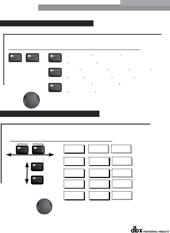
2.8 Navigating the Utility/Meters Section
From program mode, press the UTILITY button. Pressing the Data Wheel will select the effect parameter to be edited. Pressing and holding the Utility button will enter you into the meter mennu
UTILITY
<PREV PG |
|
NEXT PG> |
|
UTILITY |
|
LCD Contrast 1-16 |
|
|
|
PUP Prog. |
- |
Current/Stored |
|
|
|
ZC Panel - |
1-6 |
|
|
|
Security Level - Module Select |
|
|
|
|
|
|
|
|
|
|
|
|
|||||||
|
AEQ Plot - RTA/GEQ |
|
|
|
PUP Mute |
- |
Current/Stored |
|
|
|
(Store) - |
Edit Panel |
|
|
|
Security LevelLow, Med, High |
|
|
|
|
|
|
|
|
|
|
|
|
|
|
|
|
|
|
|
260 Device Level- |
Edit High Password |
Program List Size- 1-10 |
Program Change mode |
|
Low, Med, High |
Edit Medium Password |
List Index - |
1-10 |
Normal/Program |
|
|
|
|
Program Number Lock 1-25 |
Output Jumpers - |
1-6 |
Setting - 14, 22, 30dB
METERS
|
Noise gate- |
|
|
Limiter 1-3 |
|
|
Limiter 4-6 |
|
|
Zone Controller- |
|
|
Zone Controller- |
|
|
Output Trims |
|
|
|
Output Trims |
|
|
|
|
|
|
|
|
|
|
|
|
|
|
|
|
|||||||
|
AGC- |
|
|
|
|
|
|
|
|
1-3 |
|
|
4-6 |
|
1-3 |
|
|
4-6 |
|
||
|
|
|
|
|
|
|
|
|
|
|
|
|
|
|
|
|
|
|
|
|
|
Successive presses of the Data wheel will select effect parameters within the currently selected page.
®
DriveRack™ User Manual |
17 |
|
|
 Loading...