

Page 1
User Manual
Powered Speaker Optimizer
Featur
ing
Powered Speakers
PX
®
Page 2
IMPORTANT SAFETY INFORMATION
The symbols shown above are internationally accepted symbols that warn of
potential hazards with electrical products. The lightning flash with arrowpoint in
an equilateral triangle means that there are dangerous voltages present within
the unit. The exclamation point in an equilateral triangle indicates that it is
necessary for the user to refer to the owner’s manual.
These symbols warn that there are no user serviceable parts inside the unit.
Do not open the unit. Do not attempt to service the unit yourself. Refer all
servicing to qualified personnel. Opening the chassis for any reason will void
the manufacturer’s warranty. Do not get the unit wet. If liquid is spilled on the
unit, shut it off immediately and take it to a dealer for service. Disconnect the
unit during storms to prevent damage.
SAFETY INSTRUCTIONS
NOTICE FOR CUSTOMERS IF YOUR UNIT IS EQUIPPED WITH A POWER CORD.
WARNING: THIS APPLIANCE SHALL BE CONNECTED TO A MAINS SOCKET OUTLET WITH A
PROTECTIVE EARTHING CONNECTION.
The cores in the mains lead are coloured in accordance with the following code:
GREEN and YELLOW - Earth BLUE - Neutral BROWN - Live
As colours of the cores in the mains lead of this appliance may not correspond with the coloured
markings identifying the terminals in your plug, proceed as follows:
WARNING FOR YOUR PROTECTION
PLEASE READ THE FOLLOWING:
KEEP THESE INSTRUCTIONS
HEED ALL WARNINGS
FOLLOW ALL INSTRUCTIONS
THE APPARATUS SHALL NOT BE EXPOSED TO DRIPPING OR SPLASHING LIQUID AND NO OBJECT
FILLED WITH LIQUID, SUCH AS VASES, SHALL BE PLACED ON THE APPARATUS
CLEAN ONLY WITH A DRY CLOTH.
DO NOT BLOCK ANY OF THE VENTILATION OPENINGS. INSTALL IN ACCORDANCE WITH THE
MANUFACTURER’S INSTRUCTIONS.
DO NOT INSTALL NEAR ANY HEAT SOURCES SUCH AS RADIATORS, HEAT REGISTERS, STOVES,
OR OTHER APPARATUS (INCLUDING AMPLIFIERS) THAT PRODUCE HEAT.
ONLY USE ATTACHMENTS/ACCESSORIES SPECIFIED BY THE MANUFACTURER.
UNPLUG THIS APPARATUS DURING LIGHTNING STORMS OR WHEN UNUSED FOR LONG
PERIODS OF TIME.
Do not defeat the safety purpose of the polarized or grounding-type plug. A polarized plug has two
blades with one wider than the other. A grounding type plug has two blades and a third grounding
prong. The wide blade or third prong are provided for your safety. If the provided plug does not fit
your outlet, consult an electrician for replacement of the obsolete outlet.
Protect the power cord from being walked on or pinched particularly at plugs, convenience receptacles, and the point where they exit from the apparatus.
Use only with the cart stand, tripod bracket, or table specified by the manufacture, or sold with the
apparatus. When a cart is used, use caution when moving the cart/apparatus combination to avoid
injury from tip-over.
•
The core which is coloured green and yellow must be connected to the terminal in the plug
marked with the letter E, or with the earth symbol, or coloured green, or green and yellow.
•
The core which is coloured blue must be connected to the terminal marked N or coloured
black.
•
The core which is coloured brown must be connected to the terminal marked L or coloured
red.
This equipment may require the use of a different line cord, attachment plug, or both, depending
on the available power source at installation. If the attachment plug needs to be changed, refer
servicing to qualified service personnel who should refer to the table below. The green/yellow
wire shall be connected directly to the units chassis.
CONDUCTOR
L LIVE BROWN BLACK
N NEUTRAL BLUE WHITE
E EARTH GND
WARNING: If the ground is defeated, certain fault conditions in the unit or in the system to
which it is connected can result in full line voltage between chassis and earth ground. Severe
injury or death can then result if the chassis and earth ground are touched simultaneously.
WIRE COLOR
Normal Alt
GREEN/
YEL
GREEN
Refer all servicing to qualified service personnel. Servicing is required when the apparatus has been
damaged in any way, such as power-supply cord or plug is damaged, liquid has been spilled or objects
have fallen into the apparatus, the apparatus has been exposed to rain or moisture, does not operate
normally, or has been dropped.
MAINS DISCONNECT: The plug shall remain readily operable. For rack-mount or installation where
plug is not accessible, an all-pole mains switch with a contact separation of at least 3 mm in each
pole shall be incorporated into the electrical installation of the rack or building.
FOR UNITS EQUIPPED WITH EXTERNALLY ACCESSIBLE FUSE RECEPTACLE: Replace fuse with same
type and rating only.
MULTIPLE-INPUT VOLTAGE: This equipment may require the use of a different line cord, attachment
plug, or both, depending on the available power source at installation. Connect this equipment only
to the power source indicated on the equipment rear panel. To reduce the risk of fire or electric shock,
refer servicing to qualified service personnel or equivalent.
Page 3

If you want to dispose this product , do not m ix it w ith gene ral hous ehold waste. There is a
separate collection system for used electronic products in accordance wit h legislation that
requires proper treatment, recovery and recycling.
Private household in the 25 member states of the EU, in Switzerland and Norway may return their used
electronic products free of charge to designated collection facilities or to a retailer (if you purchase a similar
new one).
For Countries not mentioned above, please contact your local authorities for a correct method of disposal.
By doing so you will ensure that your disposed product undergoes the necessary treatment, recovery and
recycling and thus prevent potential negative effects on the environment and human health.
IMPORTANT SAFETY INFORMATION
ELECTROMAGNETIC
COMPATIBILITY
This unit conforms to the Product Specifications noted on the
Declaration of Conformity. Operation is subject to the following two
conditions:
this device may not cause harmful
•
interference, and
this device must accept any interference received, including interfer-
•
ence that may cause undesired operation.
Operation of this unit within significant
electromagnetic fields should be avoided.
use only shielded interconnecting cables.
•
DECLARATION OF
CONFORMITY
Manufacturer’s Name: dbx Professional Products
Manufacturer’s Address: 8760 S. Sandy Parkway
Sandy, Utah 84070, USA
declares that the product:
Product name: DriveRack PX
Note: Product name may be suffixed by the EU.
Product option: None
conforms to the following Product Specifications:
Safety: IEC 60065 (7th ed. 2001)
EMC: EN 55013 (2001+A1)
EN 55020 (1998)
U.K. MAINS PLUG WARNING
A molded mains plug that has been cut off from the cord is unsafe.
Discard the mains plug at a suitable disposal facility.
NEVER UNDER ANY CIRCUMSTANCES SHOULD YOU
INSERT A DAMAGED OR CUT MAINS PLUG INTO A 13
AMP POWER SOCKET.
Do not use the mains plug without the fuse cover in place.
Replacement fuse covers can be obtained from your local retailer.
Replacement fuses are 13 amps and MUST be ASTA approved to
BS1362.
Supplementary Information:
The product herewith complies with the requirements of the Low
Voltage Directive 72/23/EEC and the EMC Directive 89/336/
EEC as amended by Directive 93/68/EEC.
Director of Engineering - dbx
8760 S. Sandy Parkway
Sandy, Utah 84070, USA
Date: January 23, 2008
European Contact: Your local dbx Sales and Service Office or
Harman Music Group
8760 South Sandy Parkway
Sandy, Utah 84070, USA
Ph: (801) 566-8800
Fax: (801) 568-7583
Page 4

Table of Contents
®
DriveRack
®
PX
Section 1- Introduction ......................... 1
0.1 Defining the DriveRack PX ............... 1
0.2 Service Contact Info ....................... 2
0.3 Warranty ....................................... 3
Section 2- Getting Started ..................... 4
2.1 Rear Panel Connections .................. 4
2.2 Front Panel Connections ................. 4
2.3 Quick Start ................................... 6
2.4 DriveRack PX Wizard ....................... 8
Section 3 - Editing Functions .................. 15
3.1 Basic Navigation Modes .................. 15
3.2 Button Array Overview .................... 15
3.3 Navigating the High-pass and
Bandpass Filter (SETUP) Section ...... 16
3.4 Navigating the
Subharmonic Section ...................... 16
3.5 Navigating the
Comp/Limiter Section ..................... 17
3.6 Navigating the EQ Section .............. 17
3.7 Navigating the AFS Section ............. 18
3.8 Navigating the Utility Section ......... 18
3.9 Navigating the Wizard Section ......... 18
3.10 Navigating the Recall Section ........ 19
3.11 Navigating the Store Section ......... 19
Section 4 - Operating Functions ............... 20
4.1 Preset Definition ........................... 20
4.2 Navigating Factory Presets .............. 20
4.3 Editing Factory Presets ................... 21
Section 5 - Detailed Parameters ............... 23
5.1 Stereo Input Graphic EQ ................. 23
5.2 AFS (Automatic Feedback
Suppression)....................................... 23
5.3 Subharmonic Synthesizer ................ 25
5.4 Compressor/Limiter ........................ 26
5.5 Filter (SETUP) .............................. 28
5.6 Output Parametric EQ (3-band) ........ 28
Section 6 - Application Guide ................... 29
6.1 Mains-Only Setup (No Subs) ............ 29
6.2 Two Mains/One Subwoofer Setup ...... 30
6.3 Two Mains/Two Subwoofers Setup .... 31
6.4 Sub with Satellites Setup ................ 32
Section A - Appendix ............................... 33
A.1 Factory Reset ................................ 33
A.2 Power Up Quick Key Options............ 33
A.3 Specifications ............................... 35
A.4 Auto-EQ Optimization Tips .............. 36
A.5 Crossover Diagrams ........................ 36
A.6 Block Diagram ............................... 37
A.7 Preset List / Supported Speakers ..... 38
A.8 System Setup and Gain Structure ..... 39
Page 5
®
DriveRack
®
PX
Introduction
Section 1- Introduction
The dbx DriveRack® PX Powered Speaker Optimizer has everything you need to get the most
out of your stereo powered speaker system. It even includes stereo or mono subwoofer
support. With the included dbx M2 measurement mic, Auto-EQ corrects for audible
deficiencies in the room environment. Our patented Advanced Feedback Suppression (AFS™)
kills nasty feedback, allowing problem-free operation at higher sound levels, while our
patented Subharmonic Synthesizer™ extends bass response for enhanced bottom end. With
all that, you also get classic dbx compression and the protection offered by our graceful
PeakPlusTM limiting. Your ears, your audience, and your powered speakers will forever thank
you.
0.1 Defining the DriveRack PX
The dbx DriveRack PX is the most effective way to manage all aspects of powered loudspeaker
management for public address system applications. The DriveRack PX essentially becomes the
only device that you will need between the mixer and the powered speakers. The following
are just some of the features of the DriveRack PX.
Section 1
DriveRack® PX features:
Stereo Feedback Elimination with 12 feedback notch filters
•
Stereo 28-band Graphic EQ
•
Classic dbx® Compressor
•
120A Subharmonic Synthesizer
•
Stereo Multi-band Parametric EQ
•
Stereo PeakPlus™ Limiters
•
Pink Noise Generator
•
Auto-EQTM with 28-Band RTA
•
JBL® and other popular powered speakers included in Setup Wizard
•
JBL® preset speaker combinations
•
dbx M2 Measurement Mic and zippered pouch included
•
Front panel RTA-Mic XLR input with phantom power
•
25 User Programs / 25 Factory Programs
•
2 Channel XLR Input
•
2 Channel XLR Output
•
2 Channel XLR Sub Output
•
24-Bit ADC/24-Bit DAC, >110 dB Dynamic Range
•
dbx Type IVTM Conversion System
•
Full Graphic LCD Display
•
By including every form of processing necessary to drive the signal from the mixer to the
power amp, the DriveRack® PX allows you to eliminate all other processing devices normally
found in large and cumbersome traditional drive rack systems of the past.
The DriveRack PX Powered Speaker Optimizer includes two balanced XLR inputs and two
balanced XLR outputs, as well as two balanced XLR subwoofer output connectors.
1
Page 6

Section 1
®
®
PX
Introduction
DriveRack
0.2 Service Contact Info
If you require technical support, contact dbx Customer Service. Be prepared to accurately
describe the problem. Know the serial number of your unit - this is printed on a sticker
attached to the bottom panel. If you have not already taken the time to fill out your warranty
registration card and send it in, please do so now.
Before you return a product to the factory for service, we recommend you refer to the manual.
Make sure you have correctly followed installation steps and operation procedures. If you are
still unable to solve a problem, contact our Customer Service Department at (801) 568-7660
for consultation. If you need to return a product to the factory for service, you MUST first
contact Customer Service to obtain a Return Authorization Number.
No returned products will be accepted at the factory without a Return Authorization Number.
Please refer to the Warranty information on the following page, which extends to the first
end-user. After expiration of the warranty, a reasonable charge will be made for parts, labor,
and packing if you choose to use the factory service facility. In all cases, you are responsible
for transportation charges to the factory. dbx will pay return shipping if the unit is still under
warranty.
Use the original packing material if it is available. Mark the package with the name of the
shipper and with these words in red: DELICATE INSTRUMENT, FRAGILE! Insure the package
properly. Ship prepaid, not collect. Do not ship parcel post.
2
Page 7

®
DriveRack
®
PX
Introduction
0.3 Warranty
This warranty is valid only for the original purchaser and only in the United States.
1. The warranty registration card that accompanies this product must be mailed within 30
days after purchase date to validate this warranty. Proof-of-purchase is considered to be the
burden of the consumer.
2. dbx warrants this product, when bought and used solely within the U.S., to be free from
defects in materials and workmanship under normal use and service.
3. dbx liability under this warranty is limited to repairing or, at our discretion, replacing
defective materials that show evidence of defect, provided the product is returned to dbx
WITH RETURN AUTHORIZATION from the factory, where all parts and labor will be covered up
to a period of two years. A Return Authorization number must first be obtained from dbx by
telephone. The company shall not be liable for any consequential damage as a result of the
product’s use in any circuit or assembly.
Section 1
4. dbx reserves the right to make changes in design or make additions to or improvements
upon this product without incurring any obligation to install the same additions or
improvements on products previously manufactured.
5. The foregoing is in lieu of all other warranties, expressed or implied, and dbx neither
assumes nor authorizes any person to assume on its behalf any obligation or liability in
connection with the sale of this product. In no event shall dbx or its dealers be liable for
special or consequential damages or from any delay in the performance of this warranty due to
causes beyond their control.
3
Page 8
GND
SUB OUTPUTS
Manufactured under the following U.S. Patents:
3,789,143; 4,182,993; 6,195,029; 7,203,324.
PX
R
UL 60065 IEC 60065
120V - 60Hz
SETUP
AFS
RECALL
SUBHARMONIC
COMP/LIMITER
UTILITY
PRESET
NEXT PG
STORE
EQ
WIZARD
Inputs
Sub Outs
UTILITY
PREV PG
WIZARD
0
6
12
24
36
SIG
Headroom dB
Headroom dB
Headroom dB
Outputs
Limiter
DriveRack PX
®
Powered Speaker
Optimizer
0
6
12
24
36
SIG
0
6
12
24
36
SIG
Section 2
®
Getting Started
Section 2- Getting Started
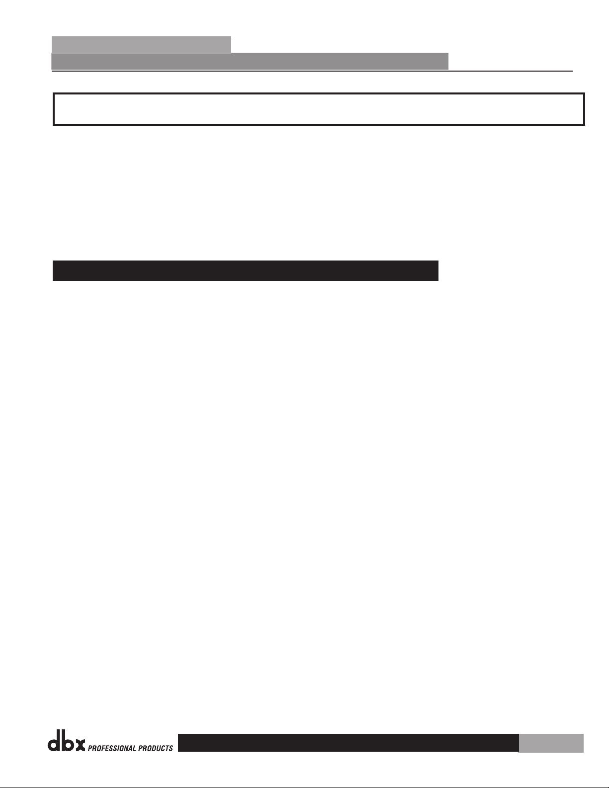
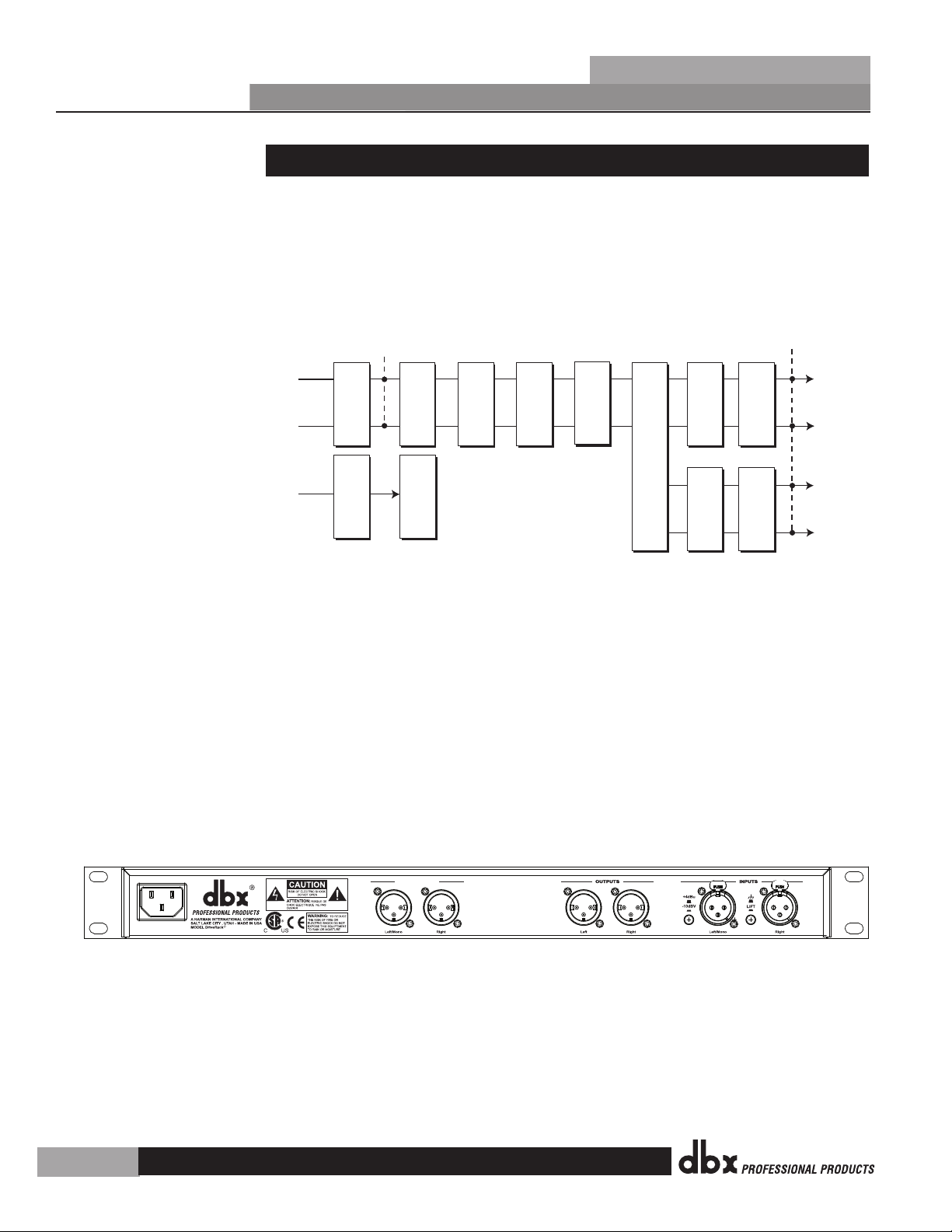
2.1 Rear Panel Connections
IEC Power Cord Receptacle
The DriveRack® PX comes with a power supply that will accept voltages ranging from 100V120V at frequencies from 50Hz-60Hz. An IEC cord is included. EU versions accept 220V-240V
at frequencies from 50Hz-60Hz.
Sub Outputs Left/Mono and Right
Connect your subwoofer(s) here (optional).
Outputs Left and Right
Connect your main speakers here.
DriveRack
®
PX
Inputs Left/Mono and Right
The input section of the DriveRack PX offers two electronically balanced XLR connectors.
Ground Lift Switch
The ground lift switch lifts the pin 1 chassis ground of both input XLR connectors.
+4dBu / –10dBV Switch
This switch selects between –10dBV and +4dBu nominal operating levels. When the switch is
in the “in” position, the –10dBV operating level is selected. When the switch is in the “out”
position, +4dBu is selected.
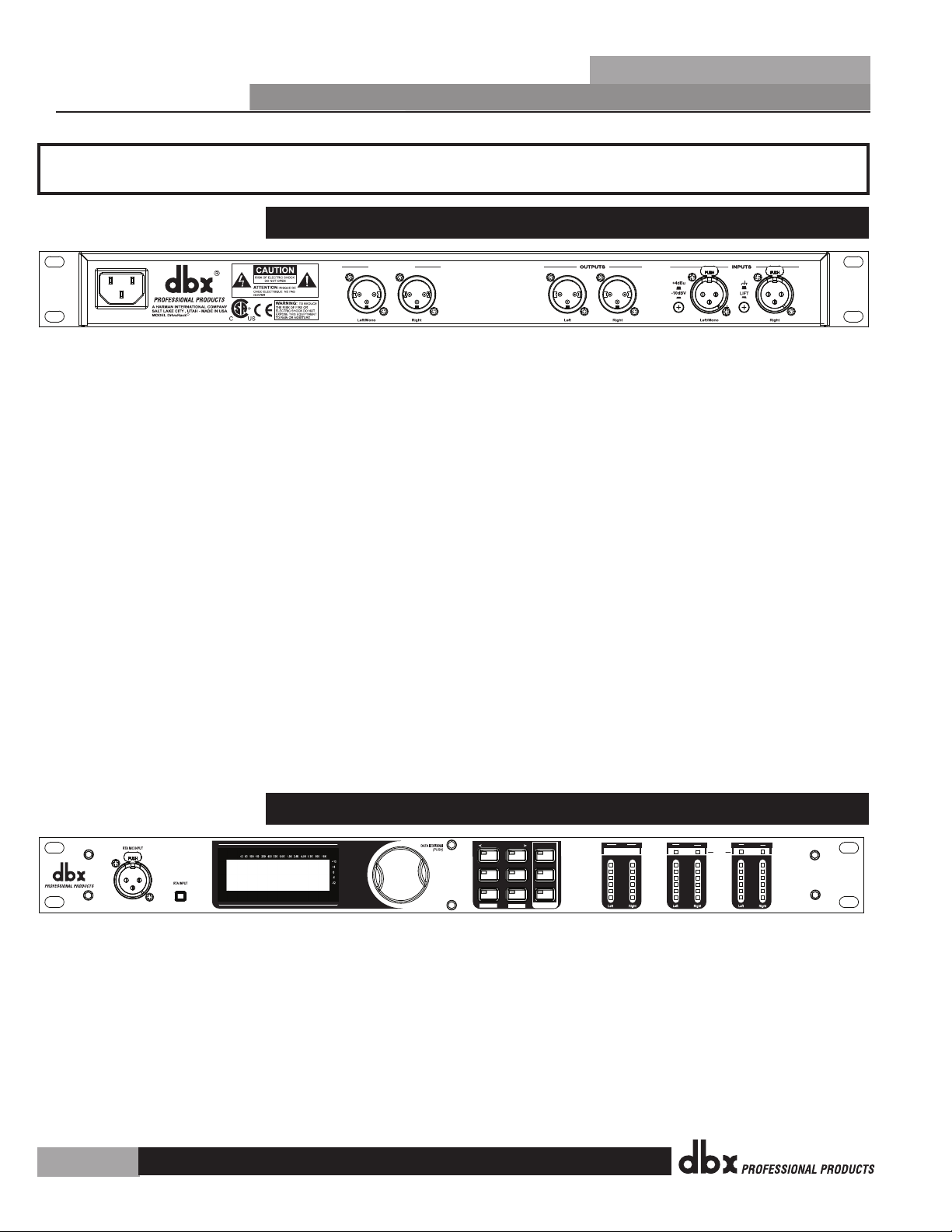
2.2 Front Panel Connections
RTA Mic Input Jack
This balanced XLR input is used for the connection of the dbx M2 RTA microphone, which
allows the user to optimize the powered speaker settings and the EQ settings of any room
through the use of the System Setup and Auto-EQ Wizards.
RTA MIC Input Selector
Pressing the RTA MIC input button will engage the front panel RTA input XLR connector and
start the Auto-EQ wizard.
4
Page 9

®
DriveRack
®
PX
Getting Started
Data Wheel
The Data wheel of the DriveRack® PX is used to scroll through the preset menu, load presets,
select parameters and edit parameter values.
LCD Display
The backlit LCD display of the DriveRack® PX provides the user with all of the vital processing
information of the DriveRack® PX including: signal routing, effect block editing and Wizard
functions. The display will also notify the user if any internal clipping is taking place within
the unit. The following message will appear: CLIP.
Function Buttons
The function buttons of the DriveRack® PX allow direct access to all editing and navigating
functions of the DriveRack® PX. The functions of the aforementioned buttons are as follows:
<PREV PG> - Moves to the previous page in the currently selected menu.
<NEXT PG> - Moves to the next page in the currently selected menu.
<SETUP> - Press and release to enter the high-pass and bandpass filter editor. Press and hold
to enter the first page of the Powered Speaker Setup Wizard.
<SUBHARMONIC> - Press and release to enter the dbx 120A Subharmonic Synthesizer editor.
<COMP/LIMITER> - Press and release to cycle through the compressor editor and output
limiter processing editor.
<EQ> - Press and release to cycle through the graphic EQ and parametric EQ editors. Press
and hold to enter the first page of the Auto-EQ Wizard.
<PRESET/[RECALL]> - Press and release to return to the preset view, showing preset number,
preset bank (user or factory), preset name, and signal path. Press and hold to activate the
[RECALL] button function which allows the selection and loading of a new preset.
<STORE/[UTILITY]> - Press and release to enter the Store menu, which allows the user to
store the current state to a user preset. Press and hold to enter the UTILITY menu to adjust
LCD contrast, Auto-EQ plot selection (RTA or GEQ), and Sales Banner on/off.
<AFS> - Press and release to enter the AFS editor. Press and hold to enter the first page of
the AFS Wizard.
Section 2
Stereo Input Meters
The DriveRack® PX provides the user with two independent six segment input meters that
range from Signal Present (–48 dBFS) to 0 dBFS (maximum output). These meters monitor the
signal level right after the input module.
Stereo Output Meters
The DriveRack® PX provides the user with two independent six-segment output meters that
range from Signal Present to 0 dBFS (maximum output).
Mono/Stereo Subwoofer Output Meters
The DriveRack® PX provides the user with two independent six-segment subwoofer output
meters that range from Signal Present to 0 dBFS (maximum output).
Threshold Meters
The threshold meters indicate that the threshold level has been exceeded within the Limiter
section, and gain reduction may be taking place within the specific output channel.
5
Page 10
GEQ
Meters
Left (Mono) Input
Right Input
Left
Right
Left (Mono)
Right
Mic Input
Outputs
Stereo Compressor
AFS Notch Filters
SubHarmonic Synth
3-Band PEQ2-Band PEQ
PeakPlus LimiterPeakPlus Limiter
High-Pass and
Band-Pass Filter Section
Stereo/Mono
Pink Noise
Micr Pre amp
RTA
Meters
Sub Outputs
GND
SUB OUTPUTS
Manufactured under the following U.S. Patents:
3,789,143; 4,182,993; 6,195,029; 7,203,324.
PX
R
UL 60065 IEC 60065
120V - 60Hz
Section 2
®
®
PX
Getting Started
DriveRack
2.3 Quick Start
For those of you that wish to jump right in, the following information has been provided to
act as a quick start guide for optimizing performance of the DriveRack® PX.
Signal Path Block Diagram
The following diagram shows the logical and intuitive signal path of the input, signal
processing modules, and output of the DriveRack® PX.
Connections
When setting up the DriveRack® PX, make connections as follows:
•
Always make connections prior to applying power to the unit.
•
Connect the output from the sending device (mixer) to one or both of the two XLR
•
input connectors shown below.
Make output connections from “Outputs” XLR connectors shown below to the inputs of
•
the powered speakers.
If a subwoofer or subwoofers are to be used, make output connections from “Sub
•
Outputs” XLR connectors shown below to the inputs of the subwoofers.
If you will be “pinking” the room through the use of the RTA, connect the dbx M2 RTA
•
microphone to the front-panel XLR input.
IMPORTANT- It is imperative that the powered speakers are turned off prior to applying
•
power to the DriveRack® PX. Always make sure that your powered speakers are the last
item turned on and the first turned off.
6
Page 11
SETUP
AFS
RECALL
SUBHARMONIC
COMP/LIMITER
UTILITY
PRESET
NEXT PG
STORE
EQ
WIZARD
Inputs
Sub Outs
UTILITY
PREV PG
WIZARD
0
6
12
24
36
SIG
Headroom dB
Headroom dB
Headroom dB
Outputs
Limiter
DriveRack PX
®
Powered Speaker
Optimizer
0
6
12
24
36
SIG
0
6
12
24
36
SIG
SETUP
AFS
RECALL
SUBHARMONIC
COMP/LIMITER
UTILITY
PRESET
NEXT PG
STORE
EQ
WIZARD
UTILITY
PREV PG
WIZARD
®
DriveRack
®
PX
Getting Started
Once all of the connections have been made and the unit is powered up, you can navigate
through the entire signal path of the DriveRack PX from the front panel of the unit. The
display provides you with a clear and concise overview of each aspect of the signal path from
the input to the output section.
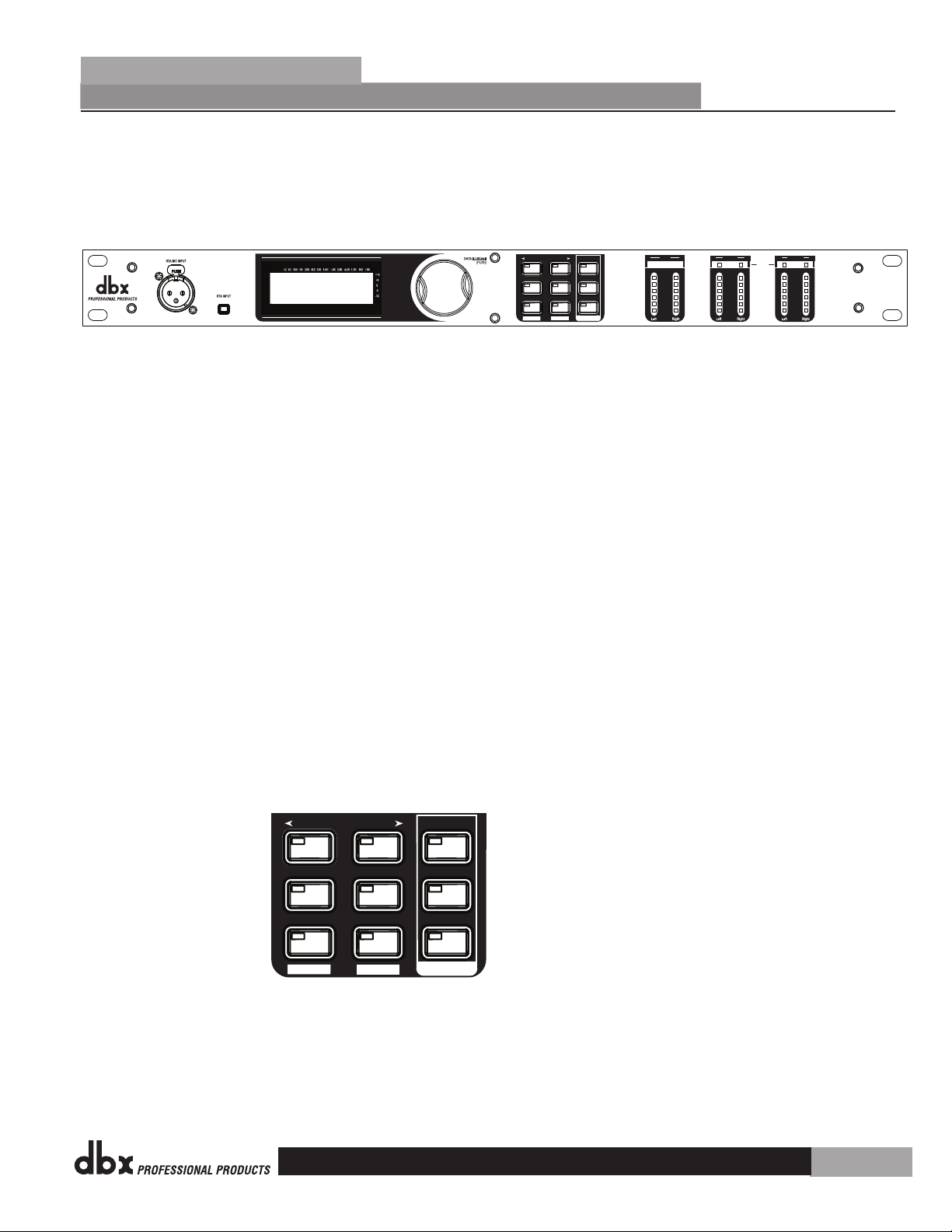
The features of the front panel of the DriveRack® PX are as follows from left to right.
RTA MIC Input - This XLR input is used for the connection of the dbx M2 RTA microphone
(included). The RTA MIC input button is used to engage the RTA input connector.
LCD Display - All operational information of the DriveRack® PX is displayed here. The display
will also notify the user if any internal clipping is taking place within the unit. The following
message will appear: CLIP.
Data Wheel - The data wheel is used to scroll through the preset menu of the DriveRack® PX.
The Data Wheel is also used to perform editing functions to signal processing and utility menu
features.
Button Array - Operational editing is done using this 9 button array. A complete description
of each button’s functionality is listed on page 5.
Input meters - These two 6-segment LED meters monitor the input level of the DriveRack® PX
directly after the input mixer.
Output Meters - These two 6-segment meters monitor the output levels of the DriveRack® PX
directly after the output gain stage.
Subwoofer Output Meters - These two 6-segment meters monitor the subwoofer output levels
of the DriveRack® PX directly after the output gain stage.
Threshold Meters - These four 1-segment meters indicate when the threshold levels of the
limiters have been exceeded.
Section 2
7
Page 12

System Setup WIZARD
EON10G2
JBL EON
Main Speakers
Section 2
®
®
PX
Getting Started
DriveRack
2.4 DriveRack PX Wizard
Now that you have made all of your audio connections and have made yourself familiar with
the front-panel navigation of the unit, you can easily optimize your system through the use
of the DriveRack® PX Wizards. These allow for quick and accurate venue setups. There are
three wizards: Setup, EQ, and AFS. Press hold any button in the Wizard section of the front
panel to access them. The wizards are designed to be used in sequence (from top to bottom),
but can be used individually as well.
Before you use the wizards, make sure the controls on your powered speakers are set the same
on both speakers. For example, if you’re using subs, and they have a polarity setting, make
sure they’re both set to the same polarity. Also, if your powered speakers have a Mic/Line
setting, make sure they’re both set to Line, and if they have their own EQ settings, disable
the EQ settings on the powered speakers.
The following section walks you through each of the wizards.
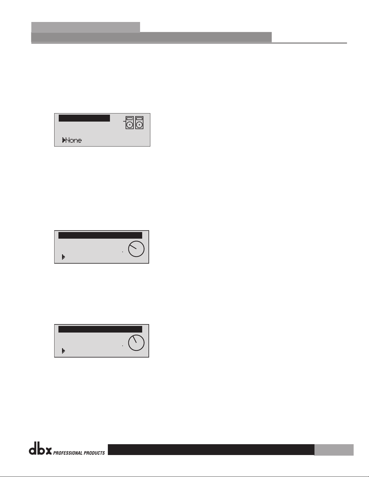
SETUP WIZARD
From preset mode, press and hold the <SETUP> button and the display will appear as
•
follows:
Press the <Next PG> button to continue.
The display will appear as follows:
•
Simply rotate the <Data> wheel to select either a Mono or Stereo input configuration.
•
Once you have selected your input option, press the <NEXT PG> button and the display
will appear as follows:
8
Page 13
Select Sub(s)
Sub Speakers
Adjust speaker
levels as shown
> 31% Level
Main Speaker Levels
Adjust speaker
levels as shown
> 40% Level
Sub Speaker Levels
®
DriveRack
Rotate the <Data> wheel to select any one of the numerous MAIN speaker options
•
available. If the speaker being used is not specified in the menu, select CUSTOM. (Note
that you can scroll by category by pressing the Select knob and placing the arrow next to
the category heading above the speaker name. Press the Select knob again to place the
arrow next to the speaker name to scroll by speaker name.) Once you have selected your
Main speaker option, press the <NEXT PG> button and the display will appear as follows:
Rotate the <Data> wheel to select any one of the numerous SUB speaker options
•
available. (Note that you can scroll by category by pressing the Select knob and placing
the arrow next to the category heading above the speaker name. Press the Select knob
again to place the arrow next to the speaker name to scroll by speaker name.) Once you
have selected your SUB speaker option, press the <NEXT PG> button.
®
PX
Getting Started
Section 2
You will now be given the option of optimizing your main speakers’ levels with the
•
DriveRack PX. The page will appear something like this:
Turn the volume (level) knob on each of your main powered speaker(s) to the position
•
shown in this screen. When you’ve done this, press the <NEXT PG> button.
If you’re using sub speaker(s), you will now be given the option of optimizing your sub
•
speakers’ levels with the DriveRack PX. The page will appear something like this:
Turn the volume (level) knob on each of your sub speakers to the position shown in this
•
screen. When you’ve done this, press the <NEXT PG> button. (If you’re not using sub
speakers, this step will be skipped.)
The display will now prompt you to load the preset you’ve just created.
•
9
Page 14
Press Select to Load
> New Preset
Load New Preset
Connect mic to RTA
input. Press RTA
input button.
Auto Level
Auto Level
Auto Level Complete
Release RTA INPUT
button to exit.
EON10g2wSub Loaded
and levels balanced.
<NEXT PG>-Auto EQ
<PRESET)-Exit Wizard
Section 2
®
Getting Started
DriveRack
®
PX
Press the <Data> wheel to load the new preset. The display will look like this:
•
The display is prompting you to connect an RTA-specific microphone to the front-panel
•
RTA XLR input, and press the <RTA Input> button. It is recommended that you use the
included dbx M2 RTA microphone, placed somewhere close to the middle of where your
audience will be. (If you wish to manually balance the individual speaker levels by ear,
you can skip the Auto Level portion of this wizard, by pressing the <Preset> button.)
Once you’ve connected the RTA microphone and pressed the <RTA Input> button, the
display will look like this:
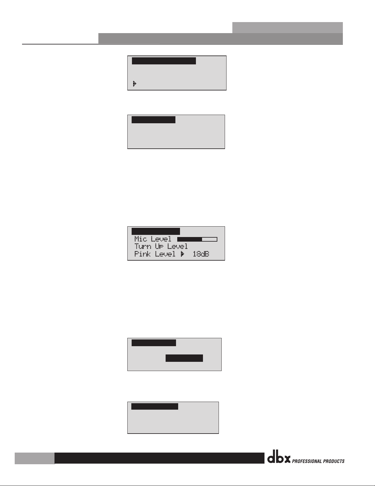
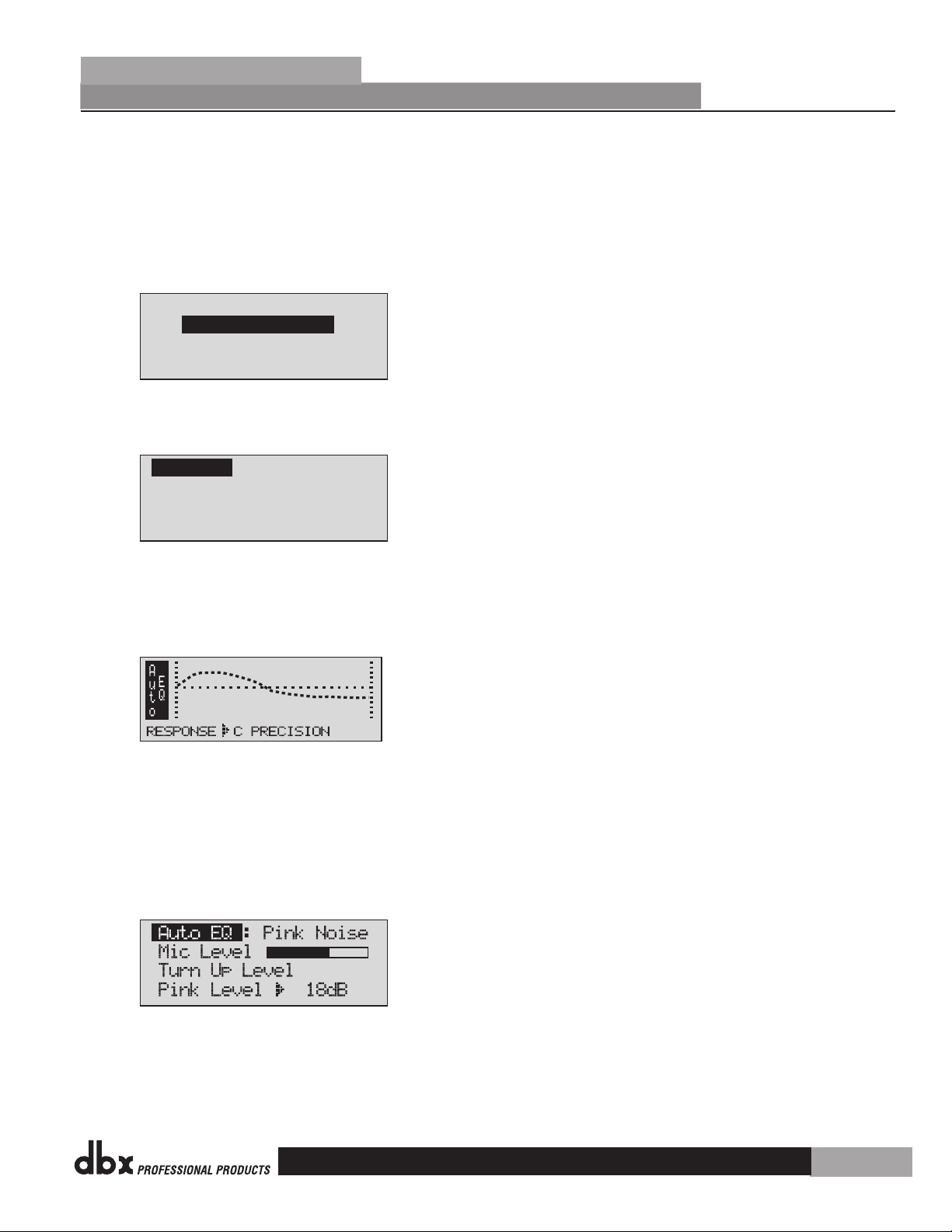
You will now proceed to “Pink” the room by adjusting the Pink level. The range of
•
bar graph is -Inf dB to +20dB. Be certain to raise the pink noise level to the level of
loudness intended during the performance. Once the Pink level has been adjusted to the
desired volume, press the <Next Pg> button and the Auto Level sequence will begin. The
DriveRack PX will adjust balance levels for your main speakers (and your subs, if you have
them). Note that you may be prompted to readjust the your speaker knob settings. When
the Auto Level sequence is finished, the display will look like this:
After you press the <RTA Input> button to release it, the display will look something like
•
this:
Press the <Next PG> button to start the Auto-EQ wizard.
10
Page 15
DriveRack PX
Auto EQ WIZARD
<NEXT PG> to advance
Connect mic to RTA
input. Press RTA
input button.
Auto EQ
MED
®
DriveRack
®
PX
Getting Started
AUTO-EQ WIZARD
Once you have completed the Setup wizard, you can now proceed to EQ your system. The
•
Auto-EQ Wizard automatically adjusts the response of the system by producing pink noise
and adjusting the Graphic EQ until the RTA matches a selected response. (The Auto-EQTM
Wizard can be initialized at any time by pressing and holding the <EQ> button.) The
display will look like this:
Press the <NEXT PG> button and the display will read:
•
Section 2
The display is prompting you to connect an RTA-specific microphone to the front-panel
•
RTA XLR input, and press the <RTA Input> button. It is recommended that you use the
included dbx M2 RTA microphone. The display will appear something like this:
You can now select any one of the several different Frequency responses for the Auto-EQ.
•
The options are: Flat (0), and Responses A-D. You can also select Low, Medium and High
Precision. Press the <Data Wheel> to toggle between selecting Response and Precision.
Turn the <Data Wheel> to scroll through the available options. Once you have selected
your desired EQ Frequency response, press the <Next pg> button and the display will
appear as follows:
You will now proceed to “Pink” the room by adjusting the Pink level. The range of bar
•
graph is –INF to +20dBu. Be certain to raise the pink noise level to the level of loudness
intended during the performance. Once the Pink level has been adjusted to the desired
volume, press the <Next pg> button and the Auto-EQ sequence will begin. The display will
11
Page 16

DriveRack PX
AFS WIZARD
<NEXT PG> to advance
Section 2
®
Getting Started
either show the graphic EQ or the RTA. Rotating the <Data> wheel clockwise and counter
clockwise will toggle between the two modes. You can also select either mode as the
default in the Utility menu. Regardless, the display will appear something like this:
At this point, the DriveRack® PX will automatically EQ to compensate for the room. Auto-
•
EQ can be aborted at any point in the process by pressing the <PREV PG> button. Upon
completion of the Auto-EQ Wizard, you can continue on to the AFS wizard by releasing
the <RTA Input> button and pressing the <Next PG> button.
For more information regarding the Auto-EQ section, please refer to the Auto-EQ Optimization
Tips information located in the Appendix section.
DriveRack
®
PX
AFS WIZARD
The DriveRack® PX also offers its exclusive patented AFS (Advanced Feedback
•
Suppression) module. This unique feature makes unwanted feedback in a PA system a
thing of the past. Once you have completed the Auto-EQTM wizard, the AFS wizard will
lead you through the setup of the fixed filters of the AFS module. (The AFS wizard can
be initiated at any time by pressing and holding the <AFS> button.) The display will look
like this:
Press the <NEXT PG> button and the display will read:
•
Once the gain level of the mixer has been turned down, press the <NEXT PG> button and
•
the display will read:
12
Page 17

Music High
Ultra Narrow Notch
®
DriveRack
You will now use the <DATA> wheel to select the number of fixed filters. This will range
•
from values 0-12. The total number of filters will stay at 12, and the number of live
filters will be = Total Num Filters – Num Fixed. Live and Fixed filter types differ in
that FIXED mode filters are automatically assigned to a frequency creating feedback,
thus remaining at that frequency until cleared by the user. In LIVE mode, live filters
automatically detect and remove feedback frequencies in the presence of audio (music
or speech). When all of the live filters have been used, they begin to round robin.
Essentially this means that the first filter set is replaced where a new feedback is
detected and notched out. This mode is useful because feedback frequencies may change
as the microphone is moved, and/or as the characteristics of the venue change.
The Fixed/Live filter usage will be indicated at the bottom of each page of the AFS menu.
‘F’ indicates an available fixed filter, and ‘L’ indicates an available live filter. A blocked
out F or L indicates a filter that is set, or in use. Once the desired number of fixed filters
has been selected, press the <NEXT PG> and the display will read:
®
PX
Getting Started
Section 2
These types pertain to the Q, sensitivity, and algorithm type. The filter is established
•
by using the formula: Q= Freq divided by Bandwidth. This means that a higher Q will
produce a filter that is more narrow. Values are: Speech (Bandwidth = 1/5 octave and
Q=7.25), Music Low (Narrow notch filter, Bandwidth = 1/10 octave and Q=14.5), Music
Medium (Very Narrow notch filter, Bandwidth = 1/20 octave and Q=29), Music High (Ultra
Narrow notch filter, Bandwidth = 1/80 octave and Q=116). To guarantee that feedback
is suppressed at lower frequencies, the AFS may place wider notch filters at these lower
frequencies (below 700 Hz). Once the desired fixed type has been selected, press the
<NEXT PG> button and the display will read:
You are now prompted to raise the output gain of the mixer to the level of the
•
performance. Once the desired level has been set and all of the fixed filters have been
assigned, the unit will automatically move you to the page that indicates the fixed filter
setup has been completed. If you have reached the performance level setting and all
of the fixed filters have not been used, you may want to return to the page that selects
the number of fixed filters and re-adjust the number of fixed in order to provide you with
additional live filters. Regardless, once you have completed the setup, the display will
read:
13
Page 18

Fixed Filter Setup
Done. In LIVE mode.
Section 2
®
Getting Started
• To return to preset mode, simply press the <PRESET> or <NEXT PG> button. For more
information regarding feedback elimination, please see the AFS parameters of the Detailed
parameters section.
DriveRack
®
PX
14
Page 19

SETUP
NEXT PG
PREV PG
SETUP
NEXT PG
SETUP
SETUP
SUBHARMONIC
COMP/LIMITER
NEXT PG
EQ
PREV PG
SETUP
COMP/LIMITER
NEXT PG
EQ
SETUP
EQ
SETUP
AFS
RECALL
COMP/LIMITER
UTILITY
PRESET
NEXT PG
STORE
EQ
WIZARD
UTILITY
PREV PG
WIZARD
®
DriveRack
Section 3 - Editing Functions
®
PX
Editing Functions
The DriveRack® PX has been carefully designed and engineered to ensure that all aspects of
operation are intuitive and logical. Simply stated, the DriveRack® PX operating system was
designed with the user’s best interest in mind.
3.1 Basic Navigation Modes
Navigational aspects of the DriveRack® PX are clear, concise and more important: flexible.
The DriveRack® PX provides you with essentially three different modes of navigation when
performing preset edits. 1. EDIT buttons - This array of 5 edit buttons is your primary mode
of directly accessing any signal processing module. 2. NEXT PG & PREV PG page buttons Successive presses of the NEXT PG or PREV PG page buttons will move the user from one page
to the next in a signal processing editor. 3. Data Wheel - The Data Wheel is used to move
through the preset menu of the DriveRack® PX. The Data wheel is also used to change the
values of the selected parameter by simply rotating the wheel. Pressing the Data wheel will
toggle between the available parameters on any selected page of the currently selected editor.
Section 3
3.2 Button Array Overview
PREVIOUS PAGE - Moves to the previous page in the currently selected
menu.
NEXT PAGE - Moves to the next page in the currently selected menu.
SETUP - Press and release to enter the high-pass and bandpass filter
editor. Press and hold to enter the first page of the Powered Speaker Setup
Wizard.
SUBHARMONIC - Selects the Subharmonic Synthesizer editor.
COMP/LIMITER - Press to cycle through the compressor editor and output
limiter editors.
EQ - Press and release to cycle through the graphic EQ and parametric EQ
editors. Press and hold to enter the first page of the Auto-EQ Wizard
PRESET/RECALL - Press and release to return to the preset view, showing
preset number, preset bank (user or factory), preset name, and signal path.
Press and hold to activate the [RECALL] button function which provides for
selection and loading of a new preset.
15
Page 20

SETUP
AFS
COMP/LIMITER
UTILITY
NEXT PG
STORE
EQ
WIZARD
UTILITY
WIZARD
SETUP
AFS
EQ
Freq - 20kH z - Out
Type -BW6-24,LR12,24
Gain - Inf t o 20dB
SETU P
To edi t t he parameters of th e h igh-pass and ban dpa ss filter used in a se lected preset, s imp ly use the followin g p rocedure.
Fro m preset mode, p res s the SETUP b utton. Once you hav e r eached the high- pas s and bandpass filt er module, navigate th rou gh the
pag es of the select ed high-pass and bandp ass filter module b y p res sing the "Next P age " or "Prev Page"
but tons successivel y u ntil arriving at th e d esired Page.
Freq - 20Hz - Out
Type- BW6-24,LR12,24
Freq - 20kH z - Out
Type- BW6-24,LR12,24
Gain - Inf t o 20dB
Successive presses of the Data wheel will select
effect parameters within the currently selected page.
SETUP
Sub Outputs Sub Outputs
Main Output s
High -pass Low- pass
High -pass
The NEXT and PRE V
bu ttons scroll through
th e pages of selected mo dul e.
<PRE V PG NE XT PG >
Navigating the Subharmonic Synthesizer Section
Subh armonic - -On /Off
Subh armonic s % 0- 100
24-3 6Hz Lev el - 2 4-36H z
36-5 6Hz Lev el - 3 6-56H z
SUBH ARMONIC
SUBHARMONIC
Fro m preset mode, press t he SUB HARMONIC button. Pre ssi ng the Data Wheel will se lec t t he parameter to be edi ted .
Successive presses of the Data wheel will select
parameters within the currently selected page.
Section 3
®
Editing Functions
DriveRack
STORE/UTILITY - Press and release to enter the Store menu, which allows
the user to store the current state to a user preset. Press and hold to
adjust LCD contrast, Auto-EQ plot selection (RTA or GEQ), and Sales Banner
on/off.
AFS - Press and release to enter the Feedback processing editor. Press and
hold to enter the first page of the AFS Wizard.
3.3 Navigating the High-pass and Bandpass Filter (SETUP) Section
®
PX
3.4 Navigating the Subharmonic Section
16
Page 21

Navigating the Compressor/Limiter Section
The Comp/Limiter bu tto n
tog gles through
the Compressor or
Lim iter modules.
COMP
Comp On/Off
Over Easy Off, 1 -10
COMP /LIMITE R
Thre shold -40-20 dB
Rati o
1:1 to ∞In f:1
Gain
-20 to 20d B
LIMITER
Limi ter On/ Off
Over Easy Off, 1 -10
Thre shold -40-20 dB
COMPRESSOR/LIMITER
Fr om preset mode, pre ss the comp/limi ter button to move to eit her the Compress or or Limiter modul e(s ). Successive press es of COMP/LIMITER but ton will will to ggl e between the
Com pressor and Limi ter modules. Naviga te through the Page s o f t he Compressor mo dul e by pressing th e
"Ne xt Page" or "Pre v P age" buttons suc ces sively until you ar riv e at the desired Pa ge.
Successive presses of the Data wheel will select
effect parameters within the currently selected page.
COMP /LIMITE R
The EQ button
tog gles through
the EQs used in
eac h channel of
the selected
pre set menu.
PEQ
GEQ
or
Navigating the "EQ Section"
To edi t t he parameters of th e E Qs used in a selected pre set , simply use the fo llo wing procedure. Fro m p res et mode,
pre ss the EQ button to re ach the EQ module t o b e e dited. Successive pre sse s of the EQ button tog gle between the GEQ an d t he PEQ.
Nav igate through the P age s of the selected E Q s ect ion by depressing " Nex t P age" or "Prev Page" su ccessively until ar riv ing at the desired Pag e.
GEQ On/Off
Flat ten/Res tore
E Q
Freq uency
Gain -12dB to12d B
PEQ On/Off
Flat ten/Res tore
Bell ,HSelf, LShel f, LH Shelf,
Band 1 Freq
Gain -12dB to12d B
Q .2 0 to 16 .0
Band 2 Freq
Gain -12dB to12d B
Q .2 0 to 16 .0
Band 3 Freq
Gain -12dB to12d B
Q .2 0 to 16 .0
Successive presses of the Data wheel will select
parameters within the currently selected page.
GEQ/PEQ
®
DriveRack
®
PX
3.5 Navigating the Comp/Limiter Section
Editing Functions
Section 3
3.6 Navigating the EQ Section
17
Page 22

The NEXT and PREV
bu ttons s cro ll through
th e pages of selected module.
Navigating the Advanced Feedback Supression (AFS) Section
AFS On/Of f
AFS Clear
Mode - Fixe d/Live
Type- Spee ch, Lo w,Med and H igh
Numb er of F ixed fi lters 0 -12
Live filter Lift - On/Off
Lift Af ter - 0 -60
AFS
AFS
Fro m prese t m ode, press the AFS button. Pre ssing t he Data Wheel will sele ct the parame ter to be edited.
<PRE V PG NEXT PG>
Successive presses of the Data wheel will select
parameters within the currently selected page.
Suc cessive presses of the Data wheel will sele ct
par ameters within the curr ently selected page.
Navigating the Utility Section
LCD Contras t 1-16
AEQ Plot - RTA/G EQ
Sale s Banne r - On/ Off
UTIL ITY
Mete r Page
UTILITY
Fro m pr eset mo de, press a nd h old the UTI LITY button . Pr essing the Data Wh eel will se lect th e pa rameter to be edit ed.
The NEXT and
PRE V butto ns
scr oll thr oug h
the pages of
sel ected m odu le.
Navigating the WIZARD Section
Inpu t Setup - Ster eo or
Mono
SETU P
- PR ESS AND HOLD TO A CCESS SETUP WIZAR D
Main Speake r Sel ect-
S ee list
Sub Speaker Sele ct-
S ee list
Main Speake r
Leve ls
Load New
Pres et
Conn ect Mic Pink Noise Level
-Inf to 20d B
Auto EQ
Sele ct Numb er of
Fixed Filte rs
- 0- 12
Mixer gain turn
down prom pt
Sele ct Type -
Low, M ed, Hig h mode
Mixer Gain Adjus t-
WIZARD
Fro m prese t m ode, pr ess and ho ld one of the WIZARD buttons ( Setup, EQ, or AFS) .
<PRE V PG
NEXT PG>
Fixed Filte r Set up
Done -
Successive presses of the Data wheel will select
parameters within the currently selected page.
Sub Speaker
Leve ls
Auto level -
Conn ect Mic
Pink Noise Level
-Inf to 20d B
Auto level
Comp lete
EQ
AFS
- PR ESS AND HOLD TO A CCESS EQ WIZ ARD
- PR ESS AND HOLD TO A CCESS AF S WIZAR D
Section 3
®
Editing Functions
3.7 Navigating the AFS Section
3.8 Navigating the Utility Section
DriveRack
®
PX
3.9 Navigating the Wizard Section
18
Page 23

PRE SET
All pre sets
RECALL
Fro m p res et mod e, press and hold the RECALL button. Turn the Data wheel to select a preset; press the Data whe el to loa d t he preset.
Turn the Data wheel to select a preset.
Press the Data wheel to load the preset.
RECALL
Cur rent ly l oade d pr eset
The NE XT and PREV
but ton s s cro ll through
the ch ara cte rs of selected preset.
Cha nge name wit h PR EV a nd
NEX T but tons and Dat a wh eel.
Cho ose a nu meri c lo cati on i n
whi ch t o st ore the pres et.
STORE
Fro m p res et mod e, press the STORE bu tto n. Pr ess the NEXT and PREV bu tto ns to sel ect characters in the preset name.
Turn th e D ata wheel to change the selected character. Press the Data wheel to toggle between upp erc ase , l owe rcase, punctuation, and numeric
cha rac ter s. Pre ss the Store button to save the name and advance to preset loc ati on scr een. Turn the Da ta whe el to select a preset location; press
the St ore bu tto n to save the preset to that location. Press the PRESET button to escape without storing.
<PR EV P G NEXT P G>
Turn the Data wheel to change the selected character.
Pre ss the St ore button to store
the na me and mo ve on to the
num eri c l oca tio n selection screen.
Turn the Data wheel to select a numeric location; press the Store button to
complete the procedure.
STOR E
®
DriveRack
®
PX
3.10 Navigating the Recall Section
3.11 Navigating the Store Section
Editing Functions
Section 3
19
Page 24

E
L
P
L
R
OUT
SUB
L
P L
Q
R
C
A
F
S
S
U
B
StOutwStSub
1
FACT
L
R
Section 4
®
Operating Functions
Section 4 - Operating Functions
The Operation section of the DriveRack® PX will be your key to successful navigation of the
operation of the DriveRack® PX. The following information provides descriptions about preset
functions and operating functions of the DriveRack® PX.
4.1 Preset Definition
The first step in understanding the capabilities of the DriveRack® PX is to understand the
elements involved, that when combined, define a complete “preset.” Within an individual
preset, there are several levels of editing that make up the complete preset. After turning
the unit on, you will be at the “preset” mode level. This level supplies the user with current
preset information such as: current signal path, signal processing, and preset name. From this
point, the DriveRack® PX gives you the option of entering subsequent levels of operation that
are dedicated to preset editing. The Utility menu mode is accessed via the utility menu, and
is not part of a single preset.
DriveRack
®
PX
4.2 Navigating Factory Presets
From the factory, the DriveRack® PX is shipped with 25 factory presets that utilize various
constructed routing configurations that have been designed to accommodate common sound
reinforcement and installation applications. The factory presets offer explanatory titles to
help get you up and running in a timely manner. These presets can also be used as templates
or starting points for the user to create custom user presets.
Selecting Presets:
The quickest way to get up and running with the DriveRack® PX is to use any one of the
factory presets that are available in the box. When you reach the factory preset, a FACT icon
(meaning “factory”) will appear above the factory preset name. From recall mode, use the
<Data> wheel to scroll through the various presets. As each factory preset is selected, the
title of each factory preset is indicated on the bottom line of the LCD to the left. You will see
that each of these these titles are directly related to a specific application. Once a preset is
selected, press the <Data> wheel to load the preset. The display will appear something like
this:
20
Navigation Modes
The function buttons of the DriveRack® PX allow direct access to all editing and navigating
functions of the DriveRack® PX. The functions of the aforementioned buttons are as follows:
Page 25

Over Easy OFF
Compressor ON
COMP THR
-50 -30 -12 -5 0
LR
-0 +
DATA - SELECTS CHAR
PREV/NEXTPG - LEFT/RIGHT:
PRESS STORE TO ADVANCE
NAME: ROCK VENUE
®
DriveRack
<PREV PG> - Moves to the previous page in the currently selected menu.
<NEXT PG> - Moves to the next page in the currently selected menu.
<SETUP> - Press and release to enter the high-pass and bandpass filter editor. Press and hold
to enter the first page of the Powered Speaker Setup Wizard.
<SUBHARMONIC> - Press to enter the dbx 120A Subharmonic Synthesizer editor.
<COMP/LIMITER> - Press to cycle through compressor editor and output limiter editors.
<EQ> -Press and release to cycle through the graphic EQ and output parametric EQ. Press and
hold to enter the first page of the Auto-EQ Wizard.
<PRESET/[RECALL]> - Press and release to return to the preset view, showing preset number,
preset bank (user or factory), preset name, and signal path. Press and hold to activate the
[RECALL] button function which provides for the selection and loading of presets.
<STORE/[UTILITY]> - Press and release to enter the Store menu, which allows the user to
store the current state to a user preset. Press and hold to adjust LCD contrast, Auto-EQ plot
selection (RTA or GEQ), and Sales Banner on/off.
<AFS> -Press and release to enter the AFS editor. Press and hold to enter the first page of the
AFS Wizard.
®
PX
Operating Functions
Section 4
4.3 Editing Factory Presets
Once you have reached the module that you wish to edit, simply use the <PREV PG> and
<NEXT PG> buttons to move through the pages within the module. The <DATA> wheel is used
to edit parameter values. The following illustration shows an example of the Comp module in
edit mode:
Note that the arrow indicates the currently selected parameter for editing. To select
parameters to edit from the current page, simply press the <DATA> wheel until the arrow is
pointing to the parameter that you wish to edit.
Once you are satisfied with the changes that have been made to a factory or user preset,
the DriveRack® PX allows you to save these changes as a custom USER preset by pressing the
<STORE> button, and the display will appear as follows:
21
Page 26

Replacing
PRESS STORE TO ADVANCE
STORE: ROCK VENUE
U1 DJ Setup
Section 4
®
Operating Functions
Rotating the <DATA> wheel will change the characters on the currently selected position.
•
Pressing the <DATA> wheel will toggle between upper and lowercase letters, numbers or
•
symbols.
Use the <PREV PG> and <NEXT PG> button to move character positions.
•
Once the desired title has been written, press the <STORE> button again and the display
•
will now appear something like this:
Rotate the <DATA> wheel to select the user preset number to be replaced and press the
•
<STORE> button again and the existing preset will be replaced with the new preset.
The DriveRack® PX will store 25 user presets in addition to the 25 factory presets.
DriveRack
®
PX
Note: Factory presets cannot be over-written. When storing changes to a Factory preset, you
must replace an existing User preset.
Note that the USER icon indicates a custom user preset, as opposed to the FACT icon.
22
Page 27

®
DriveRack
®
PX
Detailed Parameters
Section 5 - Detailed Parameters
The DriveRack® PX offers complete editing flexibility, by offering in-depth control over every
parameter within each signal processing module. The following section will provide you with
descriptions and explanations of all parameters within the DriveRack® PX.
5.1 Stereo Input Graphic EQ
EQ On/Off
Turns the GEQ on and off.
Flatten/Restore
This parameter either flattens the GEQ or restores the GEQ to the last setting before
flattening. The DriveRack PX unit allows you to leave the EQ edit window and return without
losing the edited EQ settings.
Frequency (F) 31.5Hz to 16.0kHz
This parameter allows you to select any one the 28 available frequencies.
Section 5
Gain (G) -12 to +12 dB
This parameter allows you to adjust the level of any one of the 28 bands of the GEQ in 0.5 dB
increments.
5.2 AFS (Automatic Feedback Suppression)
Feedback is caused when a microphonic signal such as a guitar pickup or microphone is
reproduced by amplification and is repeatedly picked up by the guitar pickup or microphone in
phase. AFS uses Precision Frequency Detection and state-of-the-art processing to determine
the exact portions of a given frequency of your feedback that need to be removed (instead
of taking out large sections of your sound). The AFS module of the DriveRack® PX allows the
user to optimize the elimination of feedback. In the past, graphic equalizers were used to
eliminate feedback from a system. This was an acceptable method for eliminating feedback,
but when this method was precision tested, the result clearly showed that a single 1/3
octave EQ slider was removing approximately half of the signal power. With the AFS, the
module removes the feedback automatically and the proprietary, precision AFS filters remove
only a fraction of the frequency spectrum. The following diagram shows AFS as opposed to
competitive feedback eliminators and conventional graphic EQs. The widest filter shown is a
typical 1/3 octave EQ band. The narrower filter indicates the typical bandwidth of competitors’
filters. The narrowest filter is the dbx AFS filter. The narrow filter results in highly effective
feedback suppression without compromising the sound.
23
Page 28

Section 5
®
®
PX
Detailed Parameters
DriveRack
AFS On/Off
Turns the AFS module on and off. If AFS is Off, the filters are bypassed, and the algorithm
is halted (the filters are not updated). If AFS is On, the filters are active, and the they are
updated according to the current selected mode (Fixed or Live).
Clear Live/All
This parameter clears the filters. If Clear Live is selected, then (if invoked) the live filters are
reset. If Clear All is selected, then (if invoked) all of the filters are reset. When either Clear
Live or Clear All is selected, the third parameter row displays “Start w/ Data Wheel.” If Clear
(none) is selected, then nothing is displayed on this row. When the user moves to this third
row and turns the Data Wheel (when Clear Live or Clear All is selected) then the filter reset is
invoked.
Mode - Live or Fixed
When the mode is Fixed, the algorithm updates only the fixed filters. When the mode is
Live, the algorithm updates only the live filters. In FIXED mode, the filters are automatically
assigned to a frequency creating feedback, thus remaining at that frequency until cleared by
the user. Fixed mode is used before the performance without any input signal. In LIVE mode,
the live filters automatically detect and remove feedback during the performance. When all
of the live filters have been used, they begin to round robin. Essentially this means that the
first filter set is replaced where a new feedback is detected and notched out. This mode is
useful because feedback frequencies may change as the microphone is moved, and/or as the
characteristics of the venue change.
Type - Speech, Low Music, Medium Music and High Music
If Fixed or Live mode is chosen, the text will read “Type.” The options will be Speech, Music
Low, Music Medium and Music High. These types pertain to the Q, sensitivity, and algorithm
type. Values are: Speech (Bandwidth = 1/5 octave and Q=7.25), Music Low (Bandwidth = 1/10
octave and Q=14.5), Music Medium (Bandwidth = 1/20 octave and Q=29), and Music High
(Bandwidth = 1/80 octave and Q=116). Note: To guarantee that feedback is suppressed at
lower frequencies, the AFS may place wider notch filters at these lower frequencies (below 700
Hz).
Number Fixed - 0-12
This will range from values 0-12. The total number of filters will stay at 12, and the number
of live filters will be = Total Num Filters – Num Fixed. If this is changed before the filters
are reset, then the filters will be reset one by one as the number changes. For example, if
24
Page 29

®
DriveRack
the number of Fixed filters goes down, then the last fixed filter set will be reset. Likewise, if
the number of Fixed filters goes up (and thus the number of live filters goes down), then the
last live filter set will be reset. The Fixed/Live filter usage will be indicated at the bottom
of each page of the feedback elimination effect. ‘F’ indicates an available fixed filter, and ‘L’
indicates an available live filter. A blocked out F or L indicates a filter that is set, or in use.
®
PX
Detailed Parameters
Live Filter Lift (On/Off)
This parameter turns the Live Filter Lift on and off.
Lift After - 5 sec to 60 min
This parameter allows the user to setup the box so that the Live filters will automatically
be removed after a set time (as indicated by the “Lift After” parameter). It ranges from 5
seconds to 60 minutes. This feature is useful if the microphone being used is moved or the
characteristics of the venue change over time. As an example, a filter placed minutes ago will
not likely be presently preventing feedback. This feature removes unnecessary filters from the
spectrum to ensure sonic quality. If the feedback is still there (after the filter is removed), it
will catch it and notch it out again.
Section 5
5.3 Subharmonic Synthesizer
The Subharmonic Synthesizer module has been specifically optimized to enhance Bass audio
material for use in a variety of professional applications, including nightclub and dance DJ
mixing, theatre and film sound, music recording, live music performance and broadcasting.
The Subharmonic Synthesizer module’s two separate bands of subharmonic synthesis provide
the best combination of smoothness and control, and the independent low frequency boost
circuit is designed to get the most out of high-performance low frequency speaker systems.
Sub-Harmonic Synth - On/Off
Turns the Subharmonic Synth module on and off.
Sub-Harmonics Synth - 0 to 100%
This parameter sets the overall level of the Subharmonic Synthesizer.
24-36Hz and 36-56Hz (Subharmonic Synthesis) Level - 0 to 100%
These controls individually let you customize the amount of the respective synthesized
frequencies to be added in, tuning the ultimate bass response of your system to taste. For
example, if the sound is too woofy or growly, try turning down the 36Hz-56Hz level. If your
woofers are bottoming out (making a ticking, popping sound), try turning down the 24Hz36Hz level. You may find that a setting produces fine results in one room, but produces too
much boominess in another. If this occurs, adjust the controls as needed. Experimentation
will pay off with smooth, full, deeply extended bass. Remember, you are not selecting a
frequency. You are controlling the overall level of each band.
IMPORTANT! The Subharmonic Synthesis process creates very low frequency audio material
that your powered speakers may not be designed to reproduce. Attempting to achieve
25
Page 30

Section 5
®
Detailed Parameters
enhanced bottom end with these systems may not be possible and may result in overstressing or even damaging your speakers. It is generally not a good idea to use this feature
without a subwoofer. In any case, please refer to your powered mains and powered subwoofer
speakers’ frequency response specifications, and avoid forcing them to reproduce low
frequencies that they are not designed to reproduce.
DriveRack
®
PX
5.4 Compressor/Limiter
The DriveRack® PX also offers legendary dbx OverEasy® Compression with VariKneeTM, and
proprietary dbx PeakPlusTM Limiter modules. The Compressor is a full bandwidth Stereo
Compressor located prior to the high-pass and bandpass filters. The Compressor is the perfect
tool for tightening uneven signal sources such as vocals and guitars. The PeakPlus Limiters
are located on each stereo output channel and have been strategically placed for powered
speaker protection. Note that Compressor/Limiter threshold metering can be observed on page
two of the Utility section. The parameters for the Compressor/Limiter are as follows and are
user adjustable.
COMPRESSOR
Compressor On/Off
Turns the Compressor module on and off.
OverEasy (O) Off to 10
There are ten levels of OverEasy® that can be used for the limiters. The point when the
compressor starts to compress is the “knee.” When the compressor starts to reduce the level
of a signal abruptly as it passes over the threshold, this is called “hard knee” compression.
OverEasy® (soft knee as it is sometimes called) is when the volume of the sound is
compressed gradually. OverEasy® compression starts to compress before the level of the
signal reaches the threshold and reaches full compression after the level has gone above
the threshold. OverEasy® compression, by its very nature, sounds much smoother and more
natural and will be used for most applications. When it is gentle (natural sounding or light)
compression that you are looking for, the compressor offers VariKnee™. VariKnee™ gives you
ten levels of OverEasy® compression to choose from (1 being almost hard knee and 10 being
the most OverEasy®). This lets you choose the exact knee that is needed for the dynamic
effect you are looking for.
Threshold (T) -40 to +20dBu
Threshold is the signal level at which the unit starts to compress the signal. If the level is
set to -10 dBu, than any signal larger than -10 dBu is compressed while any signal that has
a level that is lower than -10dBu is left at the same signal level. Light compression is where
only the loudest parts of the signal go over the threshold. Very heavy compression can be
achieved by setting the threshold low enough that almost the entire signal content is over
the threshold. For most signals the most natural compression is achieved when most of the
signal content remains just below the threshold and only the peaks cross the threshold.
26
Page 31

®
DriveRack
®
PX
Detailed Parameters
Ratio (R) 1.0 to Inf:1
Ratio is the amount the unit reduces the signal level of the sound that is above the threshold.
A 2:1 ratio means that if the incoming signal is 2dB over the threshold the unit will compress
the signal, and outputs a signal that only goes 1dB over the threshold. For light compression
choose a lower ratio, while a heavy compression requires a higher ratio. A setting of Inf:1
makes the compressor act more like a limiter.
Gain (G) -20 to +20 dB
This parameter is used to compensate for the gain lost during compression. By using heavy
compression on a signal and then boosting the signal with the output gain, the user can
create a signal that sounds much louder than it actually is.
LIMITER
Limiter On/Off
Turns the PeakPlusTM Limiter module on and off.
OverEasy (O) Off to 10
There are ten levels of OverEasy® that can be used for the limiters. The point when the
limiter starts to limit is the “knee.” When the limiter starts to reduce the level of a signal
abruptly as it passes over the threshold this is called “hard knee” limiting. OverEasy®
(soft knee as it is sometimes called) is when the volume of the sound is limited gradually.
OverEasy® limiting starts to limit before the level of the signal reaches the threshold and
reaches full limiting after the level has gone above the threshold. This OverEasy® limiting, by
its very nature sounds much smoother and more natural. When it is gentle (natural sounding
or light) limiting that you are looking for, the limiter offers VariKnee™. VariKnee™ gives you
ten levels of OverEasy® limiting to choose from (1 being almost hard knee and 10 being the
most OverEasy®). This lets you choose the exact knee that is needed for the type of limiting
you are looking for.
Section 5
Threshold (T) -40 to +20dBu
Threshold is the signal level at which the unit starts to limit the signal. If the level is set to
-10 dBu, any signal larger than -10 dBu is limited while any signal that has a level that is
lower than -10dBu is left at the same signal level. Light limiting is where only the loudest
parts of the signal go over the threshold. Very heavy limiting can be achieved by setting the
threshold low enough that almost the entire signal content is over the threshold. For most
signals, the most natural limiting is achieved when most of the signal content remains just
below the threshold and only the peaks cross the threshold.
27
Page 32

Section 5
®
®
PX
Detailed Parameters
DriveRack
5.5 Filter (SETUP)
The Filters are used to divide the input signal into two frequency bands. This allows the user
to drive the speaker in its optimum frequency range and send each output separately for more
efficient use of amplifier power. Appendix A.5 illustrates each of the available Filters. The
signal present at the Main (OUT) outputs can be adjusted using a High-Pass filter. The signal
present at the Subwoofer (SUB) outputs can be adjusted using Band Pass filters consisting
of Low-Pass and High-Pass filters. When editing Filter parameters the frequency band is
indicated by the highlighted OUT or SUB in the top left corner of the screen. The High-Pass
or Low-Pass filter being edited is indicated by the highlighted edge in the graphics area.
For each High Pass filter there are three parameters:
Frequency
Adjusts the frequency of the High Pass filter from OUT (below 20Hz) to 20KHz.
Type
Selects the filter type. Selections are BW 6,12,18,24 for Butterworth type filter with slope of
6, 12, 18 or 24 dB/Octave and LR12, 24 for Linkwitz-Riley type with slope of 12 or 24 dB/
Octave.
Gain
Sets the gain of the selected output band. (-INFdB to +20dB)
For each Low-Pass filter there are two parameters:
Frequency
Adjusts the frequency of the Low Pass filter from 20Hz to OUT (greater than 20kHz).
Type
Selects the filter type. Selections are BW 6,12,18,24 for Butterworth type filter with slope of
6, 12, 18 or 24 dB/Octave and LR12, 24 for Linkwitz-Riley type with slope of 12 or 24 dB/
Octave.
5.6 Output Parametric EQ (3-band)
EQ On/Off
Turns the PEQ on and off.
Flatten/Restore
This parameter either flattens or restores all bands to their original settings
Type
This parameter selects the PEQ type. Types include:
Bell - All three parametrics are bell-shaped
1.
HShelf - One shelf is High, while the other two are bell
2.
LShelf - One shelf is Low, while the other two are bell
3.
LHShelf - One shelf is High, one is Low, and the other one is bell.
4.
F1 - F3 (Frequency)
Selects the frequency of the selected band of the parametric EQ. (20Hz to 20kHz)
G (Level)
Sets the gain of the selected parametric EQ band. (-12dB to 12dB)
Q (Bandwidth)
Sets the Q (a measurement of Bandwidth) of the selected Parametric EQ. (0.20 to 16)
28
Page 33

Right Main
Pan
Mute
-10
0
+5
+10
-20
-30
-
-5
L / R
Mute
L / R
Mute
L / R
Mute
L / R
-5
-4
-3
-2
-10+1
+2
+3
+4
+5
Pan
-5
-4
-3
-2
-10+1
+2
+3
+4
+5
Pan
-5
-4
-3
-2
-10+1
+2
+3
+4
+5
Pan
-5
-4
-3
-2
-10+1
+2
+3
+4
+5
Pan
-5
-4
-3
-2
-10+1
+2
+3
+4
+5
Pan
-5
-4
-3
-2
-10+1
+2
+3
+4
+5
Pan
-5
-4
-3
-2
-10+1
+2
+3
+4
+5
Pan
-5
-4
-3
-2
-10+1
+2
+3
+4
+5
1 2 3 4
-10
0
+5
+10
-20
-30
-
-5
-10
0
+5
+10
-20
-30
-
-5
-10
0
+5
+10
-20
-30
-
-5
Mute
L / R
5
-10
0
+5
+10
-20
-30
-
-5
Mute
L / R
6
-10
0
+5
+10
-20
-30
-
-5
Mute
L / R
-10
0
+5
+10
-20
-30
-
-5
Aux 1
0
2
4 6
8
10
Aux 2
0
2
4 6
8
10
Aux 1
0
2
4 6
8
10
Aux 2
0
2
4 6
8
10
Aux 1
0
2
4 6
8
10
Aux 2
0
2
4 6
8
10
Aux 1
0
2
4 6
8
10
Aux 2
0
2
4 6
8
10
Aux 1
0
2
4 6
8
10
Aux 2
0
2
4 6
8
10
Aux 1
0
2
4 6
8
10
Aux 2
0
2
4 6
8
10
Aux 1
0
2
4 6
8
10
Aux 2
0
2
4 6
8
10
Aux 1
0
2
4 6
8
10
Aux 2
0
2
4 6
8
10
Mute
L / R
-10
0
+5
+10
-20
-30
-
-5
Mixer
JBL PRX515
Left/Mono
Main
Left/Mono Input
Right Input
SETUP
AFS
RECALL
SUBHARMONIC
COMP/LIMITER
UTILITY
PRESET
NEXT PG
STORE
EQ
WIZARD
Inputs
Sub Outs
UTILITY
PREV PG
WIZARD
0
6
12
24
36
SIG
Headroom dB
Headroom dB
Headroom dB
Outputs
Limiter
DriveRack PX
®
Powered Speaker
Optimizer
0
6
12
24
36
SIG
0
6
12
24
36
SIG
JBL PRX515
®
DriveRack
®
PX
Application Guide
Section 6 - Application Guide
This Application guide section is provided to offer suggested installation applications of the
DriveRack® PX that will allow you to optimize peak performance of the units. Note that
the 25 included application presets represent the flexibility of the DriveRack® PX. These
applications can be used verbatim, or as sample reference guide templates for designing
numerous audio applications.
6.1 Mains-Only Setup (No Subs)
Hardware
Make sure that the mixer and powered speakers are turned off prior to powering up the
1.
DriveRack® PX.
Connect the outputs from the mixer to the inputs of the DriveRack® PX.
2.
Connect the main outputs of the DriveRack® PX to the main powered speakers.
3.
Software
Use the Wizard to set up a specific preset. Press and hold the <SETUP> button to begin.
1.
See page 8 for more information.
Section 6
29
Page 34

Right Main
Pan
Mute
-10
0
+5
+10
-20
-30
-
-5
L / R
Mute
L / R
Mute
L / R
Mute
L / R
-5
-4
-3
-2
-10+1
+2
+3
+4
+5
Pan
-5
-4
-3
-2
-10+1
+2
+3
+4
+5
Pan
-5
-4
-3
-2
-10+1
+2
+3
+4
+5
Pan
-5
-4
-3
-2
-10+1
+2
+3
+4
+5
Pan
-5
-4
-3
-2
-10+1
+2
+3
+4
+5
Pan
-5
-4
-3
-2
-10+1
+2
+3
+4
+5
Pan
-5
-4
-3
-2
-10+1
+2
+3
+4
+5
Pan
-5
-4
-3
-2
-10+1
+2
+3
+4
+5
1 2 3 4
-10
0
+5
+10
-20
-30
-
-5
-10
0
+5
+10
-20
-30
-
-5
-10
0
+5
+10
-20
-30
-
-5
Mute
L / R
5
-10
0
+5
+10
-20
-30
-
-5
Mute
L / R
6
-10
0
+5
+10
-20
-30
-
-5
Mute
L / R
-10
0
+5
+10
-20
-30
-
-5
Aux 1
0
2
4 6
8
10
Aux 2
0
2
4 6
8
10
Aux 1
0
2
4 6
8
10
Aux 2
0
2
4 6
8
10
Aux 1
0
2
4 6
8
10
Aux 2
0
2
4 6
8
10
Aux 1
0
2
4 6
8
10
Aux 2
0
2
4 6
8
10
Aux 1
0
2
4 6
8
10
Aux 2
0
2
4 6
8
10
Aux 1
0
2
4 6
8
10
Aux 2
0
2
4 6
8
10
Aux 1
0
2
4 6
8
10
Aux 2
0
2
4 6
8
10
Aux 1
0
2
4 6
8
10
Aux 2
0
2
4 6
8
10
Mute
L / R
-10
0
+5
+10
-20
-30
-
-5
Mixer
JBL PRX515
Left/Mono
Main
Left/Mono
Sub
Left/Mono Input
Right Input
SETUP
AFS
RECALL
SUBHARMONIC
COMP/LIMITER
UTILITY
PRESET
NEXT PG
STORE
EQ
WIZARD
Inputs
Sub Outs
UTILITY
PREV PG
WIZARD
0
6
12
24
36
SIG
Headroom dB
Headroom dB
Headroom dB
Outputs
Limiter
DriveRack PX
®
Powered Speaker
Optimizer
0
6
12
24
36
SIG
0
6
12
24
36
SIG
JBL PRX515
JBL PRX518
Section 6
®
Application Guide
6.2 Two Mains/One Subwoofer Setup
DriveRack
Hardware
Make sure that the mixer and powered speakers are turned off prior to powering up the
1.
DriveRack® PX.
Connect the outputs from the mixer to the inputs of the DriveRack® PX.
2.
Connect the main outputs of the DriveRack® PX to the main powered speakers.
3.
Connect the Left/Mono sub output of the DriveRack® PX to the sub powered speaker.
4.
Software
Use the Wizard to set up a specific preset. Press and hold the <SETUP> button to begin.
1.
See page 8 for more information.
®
PX
30
Page 35

Right Main
Pan
Mute
-10
0
+5
+10
-20
-30
-
-5
L / R
Mute
L / R
Mute
L / R
Mute
L / R
-5
-4
-3
-2
-10+1
+2
+3
+4
+5
Pan
-5
-4
-3
-2
-10+1
+2
+3
+4
+5
Pan
-5
-4
-3
-2
-10+1
+2
+3
+4
+5
Pan
-5
-4
-3
-2
-10+1
+2
+3
+4
+5
Pan
-5
-4
-3
-2
-10+1
+2
+3
+4
+5
Pan
-5
-4
-3
-2
-10+1
+2
+3
+4
+5
Pan
-5
-4
-3
-2
-10+1
+2
+3
+4
+5
Pan
-5
-4
-3
-2
-10+1
+2
+3
+4
+5
1 2 3 4
-10
0
+5
+10
-20
-30
-
-5
-10
0
+5
+10
-20
-30
-
-5
-10
0
+5
+10
-20
-30
-
-5
Mute
L / R
5
-10
0
+5
+10
-20
-30
-
-5
Mute
L / R
6
-10
0
+5
+10
-20
-30
-
-5
Mute
L / R
-10
0
+5
+10
-20
-30
-
-5
Aux 1
0
2
4 6
8
10
Aux 2
0
2
4 6
8
10
Aux 1
0
2
4 6
8
10
Aux 2
0
2
4 6
8
10
Aux 1
0
2
4 6
8
10
Aux 2
0
2
4 6
8
10
Aux 1
0
2
4 6
8
10
Aux 2
0
2
4 6
8
10
Aux 1
0
2
4 6
8
10
Aux 2
0
2
4 6
8
10
Aux 1
0
2
4 6
8
10
Aux 2
0
2
4 6
8
10
Aux 1
0
2
4 6
8
10
Aux 2
0
2
4 6
8
10
Aux 1
0
2
4 6
8
10
Aux 2
0
2
4 6
8
10
Mute
L / R
-10
0
+5
+10
-20
-30
-
-5
Mixer
JBL PRX515
JBL PRX518
Left/Mono
Main
Right Sub
Left/Mono
Sub
Left/Mono Input
Right Input
SETUP
AFS
RECALL
SUBHARMONIC
COMP/LIMITER
UTILITY
PRESET
NEXT PG
STORE
EQ
WIZARD
Inputs
Sub Outs
UTILITY
PREV PG
WIZARD
0
6
12
24
36
SIG
Headroom dB
Headroom dB
Headroom dB
Outputs
Limiter
DriveRack PX
®
Powered Speaker
Optimizer
0
6
12
24
36
SIG
0
6
12
24
36
SIG
JBL PRX515
JBL PRX518
®
DriveRack
®
PX
Application Guide
6.3 Two Mains/Two Subwoofers Setup
Hardware
Make sure that the mixer and powered speakers are turned off prior to powering up the
1.
DriveRack® PX.
Connect the outputs from the mixer to the inputs of the DriveRack® PX.
2.
Connect the main outputs of the DriveRack® PX to the main powered speakers.
3.
Connect the sub outputs of the DriveRack® PX to the sub powered speakers.
4.
Software
Use the Wizard to set up a specific preset. Press and hold the <SETUP> button to begin.
1.
See page 8 for more information.
Section 6
31
Page 36

Left/Mono Input
Right Input
Pan
Mute
-10
0
+5
+10
-20
-30
-
-5
L / R
Mute
L / R
Mute
L / R
Mute
L / R
-5
-4
-3
-2
-10+1
+2
+3
+4
+5
Pan
-5
-4
-3
-2
-10+1
+2
+3
+4
+5
Pan
-5
-4
-3
-2
-10+1
+2
+3
+4
+5
Pan
-5
-4
-3
-2
-10+1
+2
+3
+4
+5
Pan
-5
-4
-3
-2
-10+1
+2
+3
+4
+5
Pan
-5
-4
-3
-2
-10+1
+2
+3
+4
+5
Pan
-5
-4
-3
-2
-10+1
+2
+3
+4
+5
Pan
-5
-4
-3
-2
-10+1
+2
+3
+4
+5
1 2 3 4
-10
0
+5
+10
-20
-30
-
-5
-10
0
+5
+10
-20
-30
-
-5
-10
0
+5
+10
-20
-30
-
-5
Mute
L / R
5
-10
0
+5
+10
-20
-30
-
-5
Mute
L / R
6
-10
0
+5
+10
-20
-30
-
-5
Mute
L / R
-10
0
+5
+10
-20
-30
-
-5
Aux 1
0
2
4 6
8
10
Aux 2
0
2
4 6
8
10
Aux 1
0
2
4 6
8
10
Aux 2
0
2
4 6
8
10
Aux 1
0
2
4 6
8
10
Aux 2
0
2
4 6
8
10
Aux 1
0
2
4 6
8
10
Aux 2
0
2
4 6
8
10
Aux 1
0
2
4 6
8
10
Aux 2
0
2
4 6
8
10
Aux 1
0
2
4 6
8
10
Aux 2
0
2
4 6
8
10
Aux 1
0
2
4 6
8
10
Aux 2
0
2
4 6
8
10
Aux 1
0
2
4 6
8
10
Aux 2
0
2
4 6
8
10
Mute
L / R
-10
0
+5
+10
-20
-30
-
-5
Mixer
SETUP
AFS
RECALL
SUBHARMONIC
COMP/LIMITER
UTILITY
PRESET
NEXT PG
STORE
EQ
WIZARD
Inputs
Sub Outs
UTILITY
PREV PG
WIZARD
0
6
12
24
36
SIG
Headroom dB
Headroom dB
Headroom dB
Outputs
Limiter
DriveRack PX
®
Powered Speaker
Optimizer
0
6
12
24
36
SIG
0
6
12
24
36
SIG
Left/Mono
Main
Right Main
Section 6
®
Application Guide
6.4 Sub with Satellites Setup
DriveRack
Hardware
Make sure that the mixer and powered speakers are turned off prior to powering up the
1.
DriveRack® PX.
Connect the outputs from the mixer to the inputs of the DriveRack® PX.
2.
Connect the main outputs of the DriveRack® PX to the sub powered speaker.
3.
Connect the outputs of the sub speaker to the satellite speakers.
4.
Software
Use the Wizard to set up a specific preset. Press and hold the <SETUP> button to begin.
1.
See page 8 for more information.
®
PX
32
Page 37

®
DriveRack
®
PX
Appendix
Section A - Appendix
A.1 Factory Reset
In the event that a reset is required, the DriveRack® PX offers you the option of performing
a “Soft” or “Hard” reset. The Soft Reset resets all operating parameters except user presets.
The Hard Reset Procedure will reset all preset information back to the factory defaults.
All Power-Up Functions require a button(s) to be pressed and held as the unit power is turned
on.
DriveRack PX Power-Up Button Functions
Factory (“Hard”) Reset.
Press and hold the <STORE> button at power-up until the following message appears:
“! HARD RESET?”
“Yes <PREV PAGE>”
“No <PRESET>”
• Pressing the <PREV PAGE> button will start a Factory Reset (All User Presets will become
copies of the Factory Presets, all Utility settings will be defaulted, and all Security settings
will be defaulted).
• Pressing the <Preset> button will abort the Factory Reset sequence and the unit will reset
normally.
Section A
System (“SOFT”) Reset
• Press and hold the <COMP/LIMITER> button at power-up until the following message
appears:
“! SOFT RESET?”
“Yes <PREV PAGE>”
“No <PRESET>”
• Pressing the <PREV PAGE> button will start a System Reset (All Utility settings will be
defaulted.)
• Pressing the <Preset> button will abort the System Reset sequence and the unit will reset
normally.
A.2 Power Up Quick Key Options
The DriveRack® PX offers several “Quick Key” options for initial power up and are as follow:
Change Initial Preset Number
• To change the initial power preset number, Press and hold the <PRESET> button at power-up
until the following message appears:
“Use Wheel to Change Restart Preset Number”
33
Page 38

Section A
®
Appendix
• Turning the <Data> wheel will select the preset you wish to load at initial reset.
• Press the <PRESET> button again when the selection is complete. Normal resetting will
continue.
DriveRack
®
PX
System Lock Out
• Press and hold <AFS> at power-up until one of the following messages appears (depending
on the current state of system lockout):
System Unlocked All user input will be accepted <AFS> to exit
or
System Locked! No user input will be accepted <AFS> to exit
or
Filter Unlocked. Filter clear will be accepted <AFS> to exit
Use the <DATA WHEEL> to select the desired state and then press the <AFS> button to
•
continue booting in the selected state.
The “System Unlocked” state allows normal operation.
•
The “System Locked” state is the complete lockout state. No user button input of any
•
kind will be acted upon.
The “Filter Unlocked” state is the same as the “System Locked” state except that the
•
<PRESET> and <AFS> buttons are accepted. Pressing <AFS> once will go to the AFS edit
page with the “Clear” parameter set to “LIVE” and the cursor on the third parameter
“Clear w/ <AFS>”. Pressing and holding the <AFS> button will enable a filter clear. After
the clear, the DriveRack PX will return to the preset screen.
Locked operations will cause a “LOCKED” icon to appear in the upper right corner of the
•
screen for a few seconds.
34
Page 39

®
DriveRack
®
PX
A.3 Specifications
ANALOG INPUTS:
Number of Inputs: 2 (Stereo) Line inputs
1 RTA Mic input
Connectors: 2 Female XLR line inputs
1 XLR RTA Mic input
Type: Electronically balanced, RF filtered
Impedance: >40kΩ
Max Input Line level: +20dBu
Input CMRR: >45dB
RTA Mic Phantom Voltage: +15VDC
RTA Mic EIN: <-110dBu, 22Hz-22kHz, 150Ω
ANALOG OUTPUTS:
Number of Outputs: 2 (Stereo) Line outputs
2 Sub outputs (mono or stereo)
Connectors: 2 Male XLR XLR line outputs
2 Male XLR Sub outputs
Type: Electronically balanced, RF filtered
Impedance: 120 Ω
Max Output Level: +20dBu
Appendix
Section A
A/D PERFORMANCE:
Type: dbx Type IV™ conversion system
Dynamic Range: 110dB A-weighted
107dB unweighted
Type IV dynamic range: 123dB with transient material,
A-weighted, 22kHz BW
121dB with transient material,
unweighted, 22kHz BW
115dB typical with program material,
A-weighted, 22kHz BW
Sample Rate: 48kHz
D/A PERFORMANCE:
Dynamic Range: 112dB A-weighted
110dB unweighted
SYSTEM PERFORMANCE:
Dynamic Range: 110dB A-unweighted,
>107dB unweighted, 0.002% typical at +4dBu,
1kHz, 0dB input gain
THD+N:
Frequency Response: 20Hz – 20kHz, +/- 0.5dB
Interchannel Crosstalk: <-110dB, 120dB typical
Crosstalk input to output: <-100dB
35
Page 40

Powered mains,
Mono sub
HP
BP
+
Left/Mono
Right
Powered mains,
stereo subs
HP
BP
HP
Left
Right
Left/Mono
Right
HP - High Pass Filter
BP - Band Pass Filter
Outputs
Main Outputs
Sub Outputs
Main Outputs
Sub Outputs
Left/Mono
Right
Left/Mono
Left
Right
Left
Right
Left
Right
Powered mains only,
or sub with satellite
system
Section A
®
®
PX
Appendix
DriveRack
A.4 Auto-EQ Optimization Tips
By using the setup wizard, output gains and output limiter settings are set to match your
system. The Auto-EQ can be used to adjust your system to compensate for room effects, and
to adjust the response of the entire system to your liking. After allowing Auto-EQ to “pink
the room,” your system will sound tighter. The low end will have more definition, the mids
will be more intelligible, and the highs can be tamed. Here are two things to look for to get
the best performance from the Auto-EQ.
Look out for “Modes”
Some speaker and RTA microphone positions will result in certain frequencies canceling
out. The resulting “modes” cannot be corrected with equalization. The Auto-EQ does not
detect modes in the frequency response, so it may try to boost a band to compensate for a
mode without positive affect. You may be able to see if a lifted band is a mode by manually
adjusting a lifted EQ band - if no change in the EQ is perceived, you probably are seeing a
mode in your frequency response. To reduce the effect of this mode, try different microphone
positions and adjust the location of your speakers, then repink the room for a more effective
Graphic EQ adjustment.
Adjust Output Gains
If your system setup or the response you have chosen results in the Auto-EQ lifting or cutting
a number of consecutive bands of the Graphic EQ, you can adjust the level of either the main
(OUT) gain, or the subwoofer (SUB) gain, depending on which frequencies the Auto-EQ is
applying excessive lifting or cutting, then re-pink your room. This time, the adjustment of
the Graphic EQ bands will be less “heavy handed” and the system will sound better having
fewer phase problems and a lower noise floor than a more aggressively adjusted Graphic
EQ. With the rest of your system properly adjusted, the Auto-EQ can compensate for room
resonance and adjust to suit personal taste without large excursions in the Graphic EQ bands.
A.5 Crossover Diagrams
36
Page 41

GEQ
Meters
Left (Mono) Input
Right Input
Left
Right
Left (Mono)
Right
Mic Input
Outputs
Stereo Compressor
AFS Notch Filters
SubHarmonic Synth
3-Band PEQ2-Band PEQ
PeakPlus LimiterPeakPlus Limiter
High-Pass and
Band-Pass Filter Section
Stereo/Mono
Pink Noise
Micr Pre amp
RTA
Meters
Sub Outputs
DriveRack
®
A.6 Block Diagram
®
PX
Appendix
Section A
37
Page 42

Section A
®
Appendix
A.7 Preset List / Supported Speakers
DriveRack
®
PX
PRESET LIST
StereoMains Stereo powered full-range speakers.
StMainsMSub Stereo powered full-range speakers with a mono powered subwoofer.
StMainsSSub Stereo powered full-range speakers with stereo powered subwoofers.
Sub wSats Sub with Satellite System
PRX515 2 JBL PRX515 full-range speakers
PRX515M518 2 JBL PRX515 powered full-range speakers with 1 JBL PRX518 powered
subwoofer.
PRX515S518 2 JBL PRX515 powered full-range speakers with 2 JBL PRX518 powered
subwoofers.
EON15G2 2 JBL EON15G2 full-range speakers
EON15G2MSub 2 JBL EON15G2 powered full-range speakers with 1 JBL EONSUB-G2
powered subwoofer.
EON15G2SSub 2 JBL EON15G2 powered full-range speakers with 2 JBL EONSUB-G2
powered subwoofers.
EON10G2 2 JBL EON10G2 full-range speakers
EON10G2MSub 2 JBL EON10G2 powered full-range speakers with 1 JBL EONSUB-G2
powered subwoofer.
EON10G2SSub 2 JBL EON10G2 powered full-range speakers with 2 JBL EONSUB-G2
powered subwoofers.
PRX515M118 2 JBL PRX515 powered full-range speakers with 1 JBL JRX118 powered
subwoofer.
PRX515S118 2 JBL PRX515 powered full-range speakers with 2 JBL JRX118 powered
subwoofers.
EON10G2M518 2 JBL EON10G2 powered full-range speakers with 1 JBL PRX518 powered
subwoofer.
EON10G2S518 2 JBL EON10G2 powered full-range speakers with 2 JBL PRX518 powered
subwoofers.
EON10G2M118 2 JBL EON10G2 powered full-range speakers with 1 JBL JRX118 powered
subwoofer.
EON10G2S118 2 JBL EON10G2 powered full-range speakers with 2 JBL JRX118 powered
subwoofers.
EON15G2M518 2 JBL EON15G2 powered full-range speakers with 1 JBL PRX518 powered
subwoofer.
EON15G2S518 2 JBL EON15G2 powered full-range speakers with 2 JBL PRX518 powered
subwoofers.
EON15G2M118 2 JBL EON15G2 powered full-range speakers with 1 JBL JRX118 powered
subwoofer.
EON15G2S118 2 JBL EON15G2 powered full-range speakers with 2 JBL JRX118 powered
subwoofers.
EON15G2 DJ 2 JBL EON15G2 powered full-range speakers with 2 JBL EONSUB-G2
powered subwoofers. Full Range Overlaps sub.
EON10G2 DJ 2 JBL EON10G2 powered full-range speakers with 2 JBL EONSUB-G2
powered subwoofers. Full Range Overlaps sub.
SUPPORTED SPEAKERS
Main Speakers
JBL EON 10G2
JBL EON 15G2
JBL PRX515
dB Technologies Opera Live 202
dB Technologies Opera Live 205
dB Technologies Opera Live 402
dB Technologies Opera Live 405
Mackie SRM350
Mackie SRM450
Peavey PR15P
QSC HPR 122i
QSC HPR 153i
RCF ART 310-A
RCF ART 312-A
RCF ART 315-A
RCF ART 325-A
Sampson dB500A
Yamaha MSR400
Yorkville NX55P
Subwoofers
JBL JRX118SP
JBL EON Sub G2
JBL PRX518S
dB Technologies Opera SUB12
Mackie SWA1501
Yorkville NX720S
Sub/Satellite Systems
HK Audio Lucas Impact
HK Audio Lucas Smart
38
Page 43

®
DriveRack
®
PX
Appendix
A.8 System Setup and Gain Structure
The DriveRack PX offers a wide range of tools for sound system design and setup. These tools
can make your system more efficient and better sounding, but to get the best possible sound
it is important to use these tools properly. In the DriveRack PX we have included a Wizard
setup tool to help in system setup. If you use the Wizard to set up your DriveRack PX it will
automatically set the limiters for some powered speaker selections. If your powered speakers
are not available in the Wizard, you should choose the Custom setting. The following section
explains how to maximize system gain and how to use the limiters to protect your powered
speakers from clipping.
In traditional system design, the output of your mixer would be routed to a system EQ, a
compressor, and a crossover with output level control. From the crossover, there may be
additional filters that are employed to improve the response of your speakers. There may
also be limiters set up to keep your powered speakers from going into clipping and protect
your speakers from the hazards of a clipped signal. Your powered speakers play a vital role in
system setup, because they are last item in the chain and offer the greatest amount of gain
(that is their job after all). If your powered speakers are incorrectly setup you will not be
using your system to its fullest potential.
Section A
One thing that is critical to system setup is maximizing gain structure. Gain structure refers
to aligning the gain of each device so that they all clip at the same point; and the noise
floor of the entire system is at its absolute minimum. Quite often PA systems are setup with
the amplifier input controls turned all the way up in the incorrect assumption that this is
the only way to get the maximum output level. Amplifiers are fixed gain devices, turning
down the amplifier input levels does not change the potential output of the amplifier; it only
requires more input voltage to get full output power. Many amplifiers will clip with an input
level greater than +6 dBu when the input controls are turned all the way up. Most mixing
mixers can deliver over +18 dBu of output level before clipping. This means that with your
amps tuned all the way up you are sacrificing 12 dB of headroom, resulting in poorer noise
performance and the potential of system clipping. By adjusting the amplifier controls properly,
you can maximize your system performance.
A way to set up your system for maximum gain structure is to use the clip indicators and level
meters of the mixer, DriveRack PX, and the powered speakers. To do this, hookup the output of
the mixer to the input of the DriveRack PX and the outputs of the DriveRack PX into the inputs
of your powered speakers. Set up the DriveRack PX for your particular powered speakers. Make
sure that the output limiters are turned off on the DriveRack PX. Run a continuous signal (pink
noise or sine wave – many test CDs are available that have these types of signals) through your
mixer. Turn up the output of the mixer until it begins clipping. If there is no clip indicator on
the mixer then use the output meters; most reputable mixer manufacturers use red LEDs at the
top of the meters to show the onset of clipping. Once the mixer is clipping, back the output
gain down slightly until the clip indicator on the mixer turns off. Turn up the level control on
the powered speaker until the clip indicator begins to turn on. Turn the level control down
slightly, so the clip indicator no longer is on. If the top red LED lights on the input meters on
the DriveRack PX, then you must reduce the level of the mixer feeding the DriveRack PX. If the
top red LED lights on the output meters on the DriveRack PX, then you must reduce the level
39
Page 44

Section A
®
Appendix
of that output (refer to section 5.5 -- Also note that if you turn the outputs down on the
DriveRack PX, you should turn up the level on the powered speaker until the clip LED lights
again). You have just maximized the gain through your system. These setting should give
you maximum gain without clipping, another way of say this is that when the output of your
mixer is clipping you will also be at the clip point of your powered speakers.
Once you have found the clip point of your powered speakers, you can mark this position and
turn the powered speakers back up to the point where they are clipping. You can now use the
output limiters in the DriveRack PX to protect the powered speaker from clipping no matter
what you do at the mixer. With the powered speakers clipping, now go to the Limiter page of
the DriveRack PX and turn on the limiter for each output. Make sure that the threshold is all
the way up to +20dB. Now slowly reduce the threshold until the clip indicator of the powered
speaker turns off. You have successfully set the output limiter up and the powered speaker
will not be able to go into clipping no matter what the input is. You should now proceed
to the next output and go through the same process. If you are using a sine wave to create
clipping in your powered speaker you should make sure that the sine wave is within the
frequency range of the output band that you are working with. Once all the limiters are set
up you can now turn the powered speakers back down to the gain maximized position. The
Wizard will automatically set your limiters based on your choice of powered speaker. Because
of component variances within the powered speaker circuitry, you may need to adjust the
limiter settings by a few dB after running the Wizard to ensure that they are set correctly.
DriveRack
®
PX
40
Page 45

Page 46

Page 47

Page 48

8760 South Sandy Parkway • Sandy, Utah 84070
®
A Harman International Company
Phone: (801) 568-7660 • Fax (801) 568-7662
Int’l Fax: (801) 568-7583
E-mail us at: customer@dbxpro.com
or visit us on the web at: www.dbxpro.com
18-1023-A
 Loading...