

Page 1

266XL
Owner/Operator Manual
Manuel d’utilisation
Bedienungsanleitung
Manual de instrucciones
Compressor / Gate
Page 2
WARNING
FOR YOUR PROTECTION, PLEASE READ THE FOLLOWING:
WATER AND MOISTURE: Appliance should not be used near water (e.g. near a bath-
tub, washbowl, kitchen sink, laundry tub, in a wet basement, or near a swimming pool,
etc). Care should be taken so that objects do not fall and liquids are not spilled into
the enclosure through openings.
POWER SOURCES: The appliance should be connected to a power supply only of
the type described in the operating instructions or as marked on the appliance.
GROUNDING OR POLARIZATION: Precautions should be taken so that the grounding or polarization means of an appliance is not defeated.
POWER CORD PROTECTION: Power supply cords should be routed so that they are
not likely to be walked on or pinched by items placed upon or against them, paying
particular attention to cords at plugs, convenience receptacles, and the point where
they exit from the appliance.
SERVICING: To reduce the risk of fire or electric shock, the user should not attempt to
service the appliance beyond that described in the operating instructions. All other
servicing should be referred to qualified service personnel.
FOR UNITS EQUIPPED WITH EXTERNALLY ACCESSIBLE FUSE RECEPTACLE:
Replace fuse with same type and rating only.
MULTIPLE-INPUT VOLTAGE: This equipment may require the use of a different line
cord, attachment plug, or both, depending on the available power source at installation. Connect this equipment only to the power source indicated on the equipment rear
panel. To reduce the risk of fire or electric shock, refer servicing to qualified service
personnel or equivalent.
SAFETY INSTRUCTIONS
NOTICE FOR CUSTOMERS IF YOUR UNIT IS EQUIPPED WITH A POWER
CORD.
WARNING: THIS APPLIANCE MUST BE EARTHED.
The cores in the mains lead are coloured in accordance with the following code:
GREEN and YELLOW - Earth BLUE - Neutral BROWN - Live
As colours of the cores in the mains lead of this appliance may not correspond
with the coloured markings identifying the terminals in your plug, proceed as follows:
¥ The core which is coloured green and yellow must be connected to the
terminal in the plug marked with the letter E, or with the earth symbol, or
coloured green, or green and yellow.
¥ The core which is coloured blue must be connected to the terminal
marked N or coloured black.
¥ The core which is coloured brown must be connected to the terminal
marked L or coloured red.
This equipment may require the use of a different line cord, attachment plug, or
both, depending on the available power source at installation. If the attachment
plug needs to be changed, refer servicing to qualified service personnel who
should refer to the table below. The green/yellow wire shall be connected
directly to the unit's chassis.
WARNING: If the ground is defeated, certain fault conditions in the unit or in the
system to which it is connected can result in full line voltage between chassis
and earth ground. Severe injury or death can then result if the chassis and
earth ground are touched simultaneously.
U.K. MAINS PLUG WARNING
A moulded mains plug that has been cut off from the cord is unsafe. Discard the
mains plug at a suitable disposal facility. NEVER UNDER ANY CIRCUM-
STANCES SHOULD YOU INSERT A DAMAGED OR CUT MAINS PLUG INTO
A 13 AMP POWER SOCKET. Do not use the mains plug without the fuse cover
in place. Replacement fuse covers can be obtained from your local retailer.
Replacement fuses are 13 amps and MUST be ASTA approved to BS1362.
The symbols shown above are internationally accepted symbols that warn of
potential hazards with electrical products. The lightning flash with arrowpoint in
an equilateral triangle means that there are dangerous voltages present within
the unit. The exclamation point in an equilateral triangle indicates that it is necessary for the user to refer to the ownerÕs manual.
These symbols warn that there are no user serviceable parts inside the unit.
Do not open the unit. Do not attempt to service the unit yourself. Refer all servicing to qualified personnel. Opening the chassis for any reason will void the
manufacturerÕs warranty. Do not get the unit wet. If liquid is spilled on the unit,
shut it off immediately and take it to a dealer for service. Disconnect the unit
during storms to prevent damage.
CAUTION
ELECTROMAGNETIC COMPATIBILITY
This unit conforms to the Product Specifications noted on the Declaration of
Conformity. Operation is subject to the following two conditions:
¥ this device may not cause harmful interference, and
¥ this device must accept any interference received, including interference
that may cause undesired operation.
Operation of this unit within significant electromagnetic fields should be avoided.
¥ use only shielded interconnecting cables.
DECLARATION OF CONFORMITY
ManufacturerÕs Name: dbx Professional Products
ManufacturerÕs Address: 8760 S. Sandy Parkway
Sandy, Utah 84070, USA
declares that the product: dbx 266XL
conforms to the following Product Specifications:
EMC: EN 55013 (1990)
EN 55020 (1991)
Safety: EN 60065 (1993)
IEC65 (1985) with Amendments 1, 2, 3
Supplementary Information:
The product herewith complies with the requirements of the Low Voltage Directive 73/23/EEC, and the EMC
Directive 89/336/EEC (1989), as amended by directive 93/68/EEC (1993).
dbx Professional Products
Vice President of Engineering
8760 S. Sandy Parkway
Sandy, Utah 84070, USA
February 26, 1998
European Contact: Your Local dbx Sales and Service Office or
International Sales Office
68 Sheila Lane
Valparaiso, Indiana Tel: (219) 462-0938
46383, USA Fax: (219) 462-4596
WARRANTY
1. The warranty registration card that accompanies this product must be mailed within 30 days after purchase
date to validate this warranty. Proof-of-purchase is considered to be the burden of the consumer.
2. dbx warrants this product, when bought and used solely within the U.S., to be free from defects in materials and workmanship under normal use and service.
3. dbx liability under this warranty is limited to repairing or, at our discretion, replacing defective materials that
show evidence of defect, provided the product is returned to dbx WITH RETURN AUTHORIZATION from
the factory, where all parts and labor will be covered up to a period of two years. AReturn Authorization
number must be obtained from dbx by telephone. The company shall not be liable for any consequential
damage as a result of the product's use in any circuit or assembly.
4. dbx reserves the right to make changes in design or make additions to or improvements upon this product
without incurring any obligation to install the same additions or improvements on products previously manufactured.
5. The foregoing is in lieu of all other warranties, expressed or implied, and dbx neither assumes nor authorizes any person to assume on its behalf any obligation or liability in connection with the sale of this product. In no event shall dbx or its dealers be liable for special or consequential damages or from any delay in
the performance of this warranty due to causes beyond their control.
RISK OF ELECTRIC SHOCK
DO NOT OPEN
ATTENTION: RISQUE DE CHOC ELECTRIQUE - NE PAS OUVRIR
WARNING: TO REDUCE THE RISK OF FIRE OR ELECTRIC
SHOCK DO NOT EXPOSE THIS EQUIPMENT TO RAIN OR MOISTURE
CONDUCTOR
L
N
E
LIVE
NEUTRAL
EARTH GND
WIRE COLOR
Normal Alt
BROWN
BLUE
GREEN/YEL
BLACK
WHITE
GREEN
Page 3

266XL
MANUAL CONTENTS
ENGLISH . . . . . . . . . . . . . . . . . . . . . . . . . . . . . . . . . . . . . . . . . . . . . . . . .2
FRAN‚AIS . . . . . . . . . . . . . . . . . . . . . . . . . . . . . . . . . . . . . . . . . . . . . . . .9
DEUTSCH . . . . . . . . . . . . . . . . . . . . . . . . . . . . . . . . . . . . . . . . . . . . . . .19
ESPA„OL . . . . . . . . . . . . . . . . . . . . . . . . . . . . . . . . . . . . . . . . . . . . . . . .29
ENGLISH CONTENTS
INTRODUCTION . . . . . . . . . . . . . . . . . . . . . . . . . . . . . . . . . . . . . . . . . . . . . . 2
OPERATING CONTROLS . . . . . . . . . . . . . . . . . . . . . . . . . . . . . . . . . . . . . . . . 3
COMPRESSOR SECTION . . . . . . . . . . . . . . . . . . . . . . . . . . . . . . . . . . . . . . . . 4
EXPANDER/GAT E SECTION . . . . . . . . . . . . . . . . . . . . . . . . . . . . . . . . . . . . . . 5
CONNECTING THE 266XL TO YOUR SYSTEM . . . . . . . . . . . . . . . . . . . . . . . . 7
TECHNICAL SUPPORT / FACTORY SERVICE . . . . . . . . . . . . . . . . . . . . . . . . . . . 8
R
EGISTRATION AND USER FEEDBACK . . . . . . . . . . . . . . . . . . . . . . . . . . . . . . 8
SPECIFICATIONS . . . . . . . . . . . . . . . . . . . . . . . . . . . . . . . . . . . . . . . . . . . . 39
BLOCK DIAGRAM . . . . . . . . . . . . . . . . . . . . . . . . . . . . . . . . . . . . . . . . . . . 41
Compressor / Gate
Page 4

Congratulations on choosing the dbx 266XL Compressor/Gate. The 266XL provides
traditional dbx sonic quality and performance for the working musician, DJ, studio
operator or anyone who needs a friendly compressor/gate to achieve quality compression, gating and downward expansion quickly and easily. We recommend that you take
a moment and read through the manual as it provides information that will assist you
in using your unit to its fullest potential.
The 266XL's compressor is packed with just the right features to effectively reduce
and control the dynamic range of your audio, add punch to flabby, loose sounds, or
add sustain to instruments. The 266XL begins with the classic dbx compression made
famous by our 160 line of compressors. Just set the 266XL's Attack and Release controls to 12:00 to get the same response as those units. But there's more. We scaled the
program-dependent Attack and Release controls with dbx's new AutoDynamicª circuitry, so that the 266XL's full range of controls produce voicings that extend from
slow leveling to aggressive peak limiting.
Common Compressor Applications:
¥ Fattening a Kick Drum or Snare Drum
¥ Adding Sustain to Guitar or Synthesizer String Sounds
¥ Smoothing Out a Vocal Performance
¥ Raising a Signal Out of a Mix
¥ Preventing Sound System Overload
¥ Digital to Analog Transfers
The 266XL's gate is ready to tackle all your gating needs, whether you need to remove
unwanted noise or other background sounds, tighten drum sounds, or change the characteristic envelope of an instrument. The 266XL's gate provides more flexibility than
traditional switch gates because it actually functions as a combination gate/expander.
Where switch gates are generally only suitable for a limited number of uses (e.g., gating percussion), the gate on the 266XL acts as a gentle downward expander at low
Ratio settings (suitable for vocals, guitar, mixed program, etc.), and can effectively
work as a switch gate when used at high Ratio settings.
Common Gating Applications:
¥ Gating Dry Percussive Sounds (e.g., Snare Drum, Kick Drum)
¥ Gating Sounds That Have Longer Decay (e.g., Cymbal, Piano)
¥ Gating Hum or Buzz From Live Instruments or Recorded Tracks
¥ Downward Expansion to Reduce Noise Under Smooth Sounds (e.g., Vocals,
Woodwinds)
Refer to the following pages for suggested initial settings. These settings should suffice for traditional compressing and gating requirements. However, the 266XL can
accomplish many more changes to sound quality. We recommend that you experiment
with the 266XL's controls; take our suggested settings and run with them, try totally
different settings, and try unorthodox combinations of compressor and gating controls.
You might be surprised at what you hear. Best of all, you may create the perfect sound
quality for your needs.
INTRODUCTION
2
266XL
Compressor / Gate
Page 5
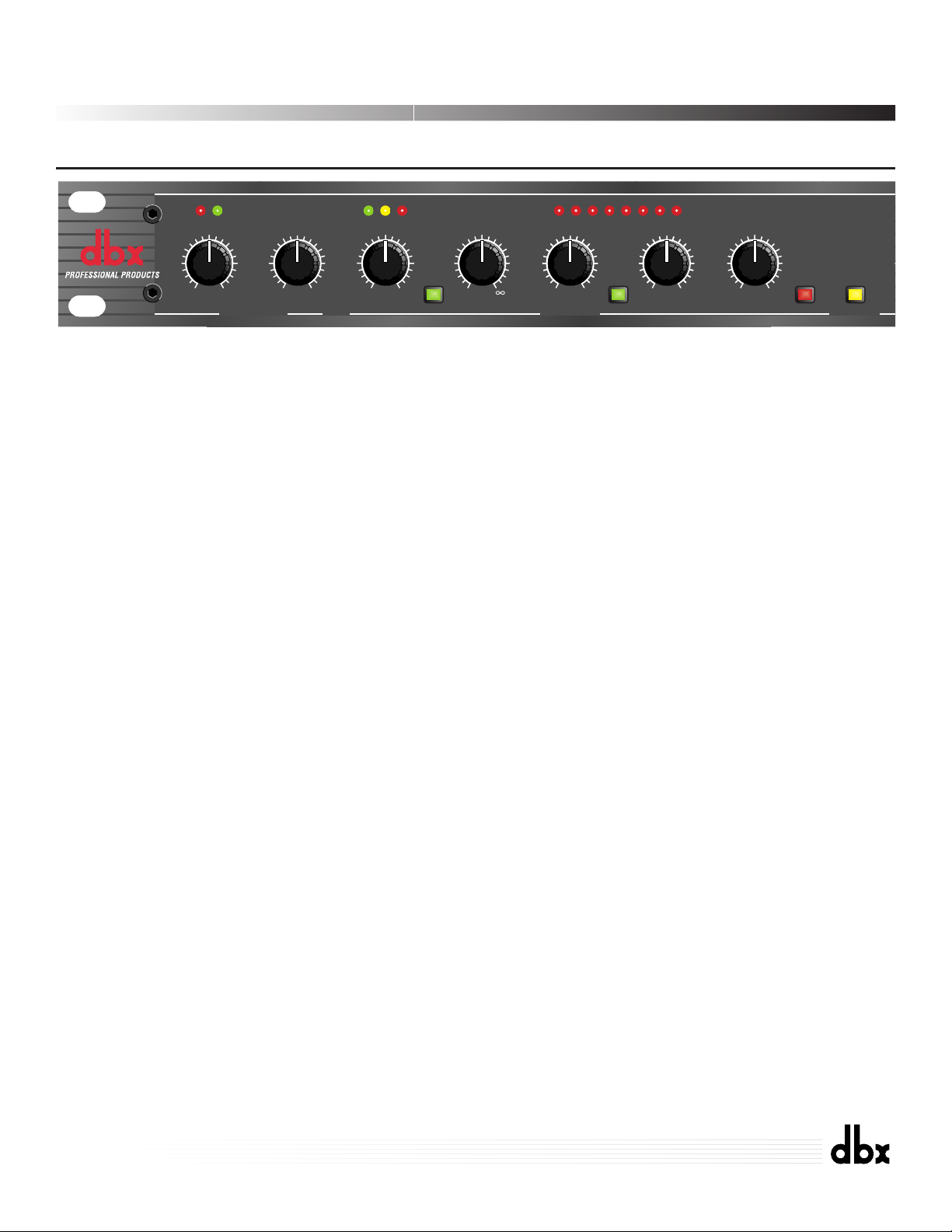
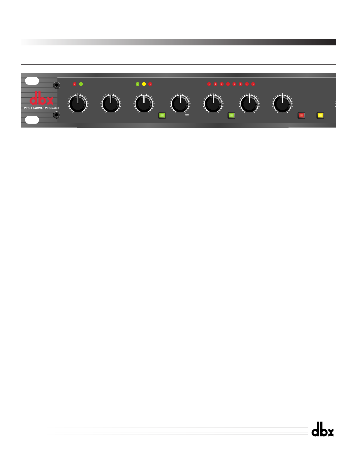
OPERATING CONTROLS
Front Panel
3
STEREO COUPLE Switch and LED
This switch sets the 266XL for Stereo or Dual Mono operation. Press the STEREO
COUPLE switch in for stereo operation where Channel 1 becomes the master controller for both channels. All of Channel 2's controls, switches, and LEDs will be disabled (except for Channel 2's GAIN REDUCTION meter), since Channel 2 is the
slave.
With the STEREO COUPLE switch out, the unit functions as two separate mono
compressor/gates, each with its own independent controls.
The red STEREO COUPLE LED indicates that the 266XL is stereo-coupled.
BYPASS Switch and LED
Press this switch in to bypass the front panel controls, effectively canceling the function and processing effect of the 266XL's compression, gating and gain settings. The
input signal is still present at the 266XL's Output, but is now unaltered by the
266XL's controls. BYPASS is especially useful for making comparisons between
processed and unprocessed signals. Note that with stereo operation (STEREO COUPLE switch pressed in), the Channel 1 BYPASS switch controls both channels.
The red BYPASS LED lights when BYPASS is active.
GAIN REDUCTION (dB) Meter
This meter displays the amount of signal attenuated from the input signal by the
266XL's Compressor or Expander/Gate. When the Compressor and Expander/Gate
are both active, the meter displays the maximum amount of gain reduction for
whichever function is greater - Compressor or Expander/Gate.
OUTPUT GAIN (dB) Control:
This control sets the overall gain of the 266XL, from -20dB to +20dB. The OUTPUT
GAIN control is especially useful to compensate for the RMS level decrease which
results from the 266XL's dynamic processing effects. After you adjust the 266XL's
controls for the desired amount of compression, set the OUTPUT GAIN to add the
same amount of gain that is shown on the GAIN REDUCTION meters. For example,
if the average amount of gain reduction shown on the meters is 10dB, then setting the
OUTPUT GAIN control to +10dB will compensate for the 10dB average level reduction at the output.
Note: the 266XL's Compressor and Expander/Gate control settings are interactive and can affect gain, so
watch your playback levels.
0
266XL
Compressor / Gate
-
+
CHANNEL ONE
-40
-60
OFF
+15
dBu
2:1
-20
0
1.3:1
1:1 4:1
RATIO ATTACK
THRESHOLDTHRESHOLD GAIN REDUCTION dB
+
-
0
-10
-20
3:1
-30
0
+10
-40
+20
dBu
THRESHOLDTHRESHOLD
1.3:1
2:1
4:1
1:1
RATIO
FAST
:1
COMPRESSOREXPANDER/GATE
AutoOverEasy
SLOW
1361015202530
-10 +10
FAST
SLOW
RELEASE OUTPUT GAIN
-20
0
+20
dB
Stereo
CoupleBypass
-6
Page 6

Note: Setting the Compressor RATIO to 1:1 will turn the Compressor off, regardless of the setting of the
Compressor THRESHOLD control and BELOW/OVEREASY/ABOVE LED status. Setting the Compressor
THRESHOLD control to +20dB will prevent all but the highest level peaks from being compressed.
OVEREASY¨ Switch
Depress this switch to select the OverEasy¨ compression characteristic. The yellow
THRESHOLD LED turns on when the signal is in the OverEasy region. When the
switch is out, the 266XL operates as a hard-knee compressor, and the yellow LED
does not light.
Compressor THRESHOLD Control and LEDs (BELOW/OVEREASY/ABOVE):
Adjust this control to set the threshold of compression from - 40dB to +20dB. In hardknee mode, the threshold of compression is defined as the point above which the output level no longer changes on a 1:1 basis with changes in the input level.
In OverEasy mode the threshold of compression is defined as the middle of the
OverEasy threshold region, that is, Òhalf-wayÓ into compression.
The three THRESHOLD LEDs indicate the relationship of the input signal level to the
threshold of compression. The green LED lights when the signal is BELOW threshold,
the red LED lights when the signal is above threshold, and the yellow LED lights
when the OVEREASY switch is depressed and the input signal is in the OVEREASY
range.
The 266XL's OverEasy compression permits extremely smooth, natural sounding compression, without artifacts, due to the gradual change of compression around the
threshold. With OverEasy compression, input signals begin to gradually activate the
266XL's internal gain change circuitry as they approach the THRESHOLD reference
level. They do not get fully processed by the RATIO, ATTACK and RELEASE controls until they have passed somewhat above the THRESHOLD reference level. As the
signal level passes the THRESHOLD level, processing increases until it is fully
processed to the extent determined by the control settings.
In hard-knee mode, the 266XL can provide abrupt compression effects as well as hardlimiting applications. Note that when in hard knee mode the yellow LED will not light
as the input signal passes across the threshold. The signal is either being compressed
(over threshold) or it is not being compressed (under threshold).
Note: Even though no input signal is being applied, it is normal for the LEDs to flicker on when the power is
applied or removed.
Compressor RATIO Control:
Adjust this control to set the amount of compression applied to the input signal.
Clockwise rotation of this control increases the compression ratio from 1:1 (no compression) up to °:1 (where the compressor can be considered to be a peak limiter,
especially with faster ATTACK settings).
COMPRESSOR SECTION
4
266XL
Compressor / Gate
Page 7

EXPANDER/GATE SECTION
5
When an input is above the THRESHOLD setting reference level, the RATIO setting
determines the number of decibels by which the input signal must increase in level to
produce a 1dB increase in the signal level at the output of the 266XL. A setting of 2:1
indicates an input/output ratio wherein a 2dB increase in signal (above threshold) will
produce a 1dB increase in output signal. A setting of °:1 indicates that an infinite
increase in input level would be required to raise the output level by 1dB.
Compressor ATTACK and RELEASE Control:
The ATTACK control sets the amount of time it takes the 266XL to begin compressing a signal once the detector has sensed a signal above threshold. The ATTACK
range is from FAST (for a tighter and more noticeable compression effect with very
little overshoot) to SLOW (for more delayed, gradual compression). A very fast
ATTACK setting will cause the 266XL to act like a peak limiter even though RMS
detection circuitry is used. Slower ATTACK settings cause the 266XL to act like an
RMS or averaging detecting compressor/limiter.
The RELEASE control sets how fast the compression circuit returns the input to its
original level. The RELEASE rate is from FAST (where compression follows the
envelope of the program material very tightly) to SLOW (for very smooth compression).
There is no absolute right way to set the ATTACK and RELEASE controls. However,
in general, you will want them set slow enough to avoid pumping or breathing
sounds caused when background sounds are audibly modulated by the dominant signal energy, yet the release must be fast enough to avoid suppression of the desired
signal after a sudden transient or loud note has decayed. For low frequency tones
(e.g., bass guitar), set RELEASE and ATTACK to 2:00 or slower.
Note: ATTACK and RELEASE controls operate together and in conjunction with the RATIO control.
Changing one control may necessitate changing another setting.
Auto Switch:
This switch overrides both the ATTACK and RELEASE controls and enables preset
program-dependent attack and release times. These times are derived from the input
signal and continuously change to match its dynamics. Enabling this AUTO Function
duplicates the Òclassic dbx soundÓ of the 266XLÕs forerunners which have become
standards in the industry.
Note: The Expander/Gate is off when the Expander/Gate THRESHOLD is set to OFF.
Expander/Gate THRESHOLD Control and LEDs (BELOW/ABOVE):
Adjusting this control sets the level at which the gate will open and allow the signal
at the input to pass through to the output. Turning the knob fully counterclockwise (to
OFF) allows the gate to pass all signals unattenuated, effectively bypassing the gate.
Turning the knob fully clockwise causes the gate to attenuate input signals below
+15dBu. The depth of attenuation depends on the setting of the Expander/Gate
RATIO control.
The two Expander/Gate LEDs indicate the relationship of the input signal level to the
threshold setting. The red LED lights when the signal is BELOW threshold, the green
LED lights when the signal is ABOVE threshold.
266XL
Compressor / Gate
Page 8
Expander/Gate RATIO Control:
This control sets the amount of attenuation applied to the input signal once it is below
the threshold, from gentle downward expansion (appropriate for mixed program,
vocals, etc.), to a hard gating effect (which can be useful for percussion). Fairly low
RATIO (and higher Expander/Gate THRESHOLD) settings work best for downward
expansion, whereas higher RATIO settings (clockwise towards MAX) work best for
gating. If a setting produces undesirable pumping, readjust the Expander/Gate RATIO
or THRESHOLD setting.
Note: The attack and release rate of the Expander/Gate are program-dependent - very fast for transient
material (e.g., percussion) and slower for material with slow attack (e.g., vocals).
Note: Fast gating of sustained low frequency signals can result in “chattering”. To eliminate any “chattering”
simply adjust the RATIO control. The proper THRESHOLD setting will also minimize false triggering and
“chattering.”
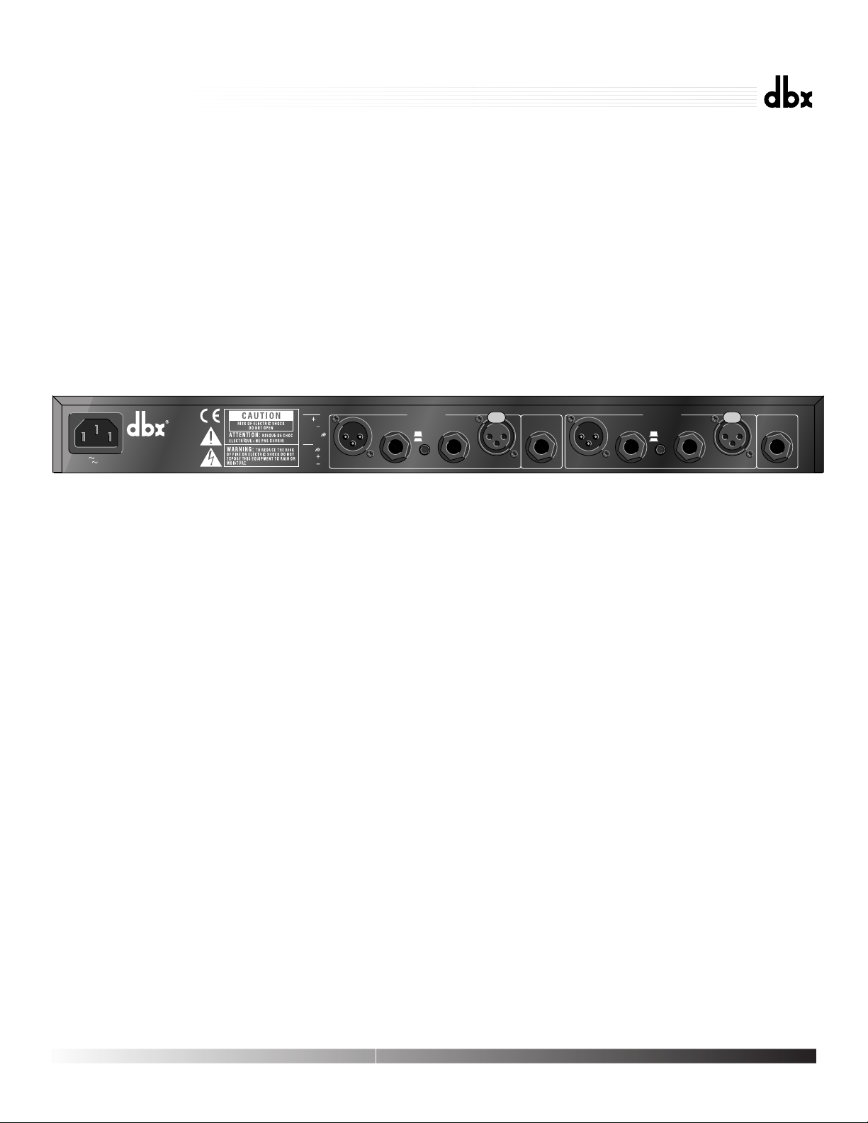
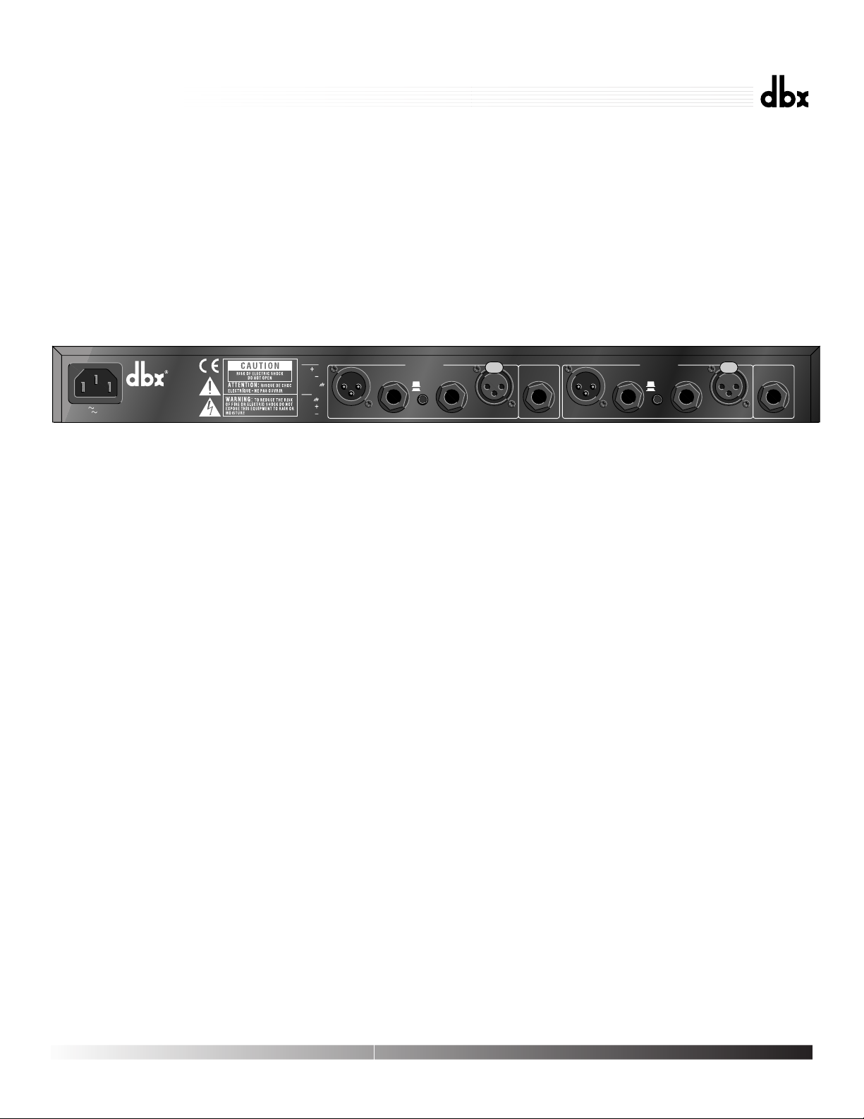
INPUT Jacks (CHANNEL 1 and 2):
Use 1/4Ó phone plugs or male XLR plugs to connect these inputs to your source. The
266XL's INPUT jacks accept either balanced or unbalanced signals. Input impedance
is >40k½.
OUTPUT Jacks (CHANNEL 1 and 2):
The OUTPUT jacks accept 1/4Ó balanced or unbalanced phone plugs or female XLR
plugs. Maximum output signal level is >+20dBu. In the +4dBu setting, the balanced
output impedance is 100½, and the unbalanced output impedance is 50½. In the
-10dBV setting, the balanced output impedance is 1k½ and the unbalanced output
impedance is 500½.
OPERATING LEVEL Switch
This switch selects between a -10dBV and +4dBu nominal operating level. When the
switch is in the IN position, a -10dBV operating level is selected. When it is in the
OUT position, a +4dBu operating level is selected. Note that the switch is slightly
recessed. This is to provide protection against accidental activation, possibly causing
damage to other system components due to a sudden change in gain.
SIDECHAIN INSERT Jack:
This jack accepts 1/4Ó TRS phone plugs and provides a connection to the 266XL
detector path. The RING acts as a Send, carrying a buffered version of the signal present at the 266XL INPUT jack, at an impedance of 2k½. The TIP acts as a Return for
equipment to feed the 266XL's detector circuitry, such as an equalizer for de-essing or
frequency-sensitive gating/compression. You can also drive the 266XL Sidechain input
with the output of most equipment, by using a 1/4Ó mono phone plug. Input
Impedance is greater than 10k½.
Note: When a cable is plugged into this jack, it automatically breaks the connection from the INPUT jack to
the 266XL's detection circuitry.
Rear Panel
6
15 WATTS
100V 50/60Hz
120V 60Hz
PROFESSIONAL PRODUCTS
A HARMAN INTERNATIONAL
COMPANY
SALT LAKE CITY, UTAH
MADE IN USA
MODEL 266XL
COMPRESSOR/GATE
MANUFACTURED UNDER ONE OR MORE OF THE FOLLOWING U.S. PATENTS 4,234,804 4,316,107 4,329,598 4,331,931 4,377,792 4,403,199 4,409,500 4,425,551 4,434,380 4,454,433 4,471,324 4,473,793 OTHER PATENTS PENDING
PHONE:
TIP
RING
SLEEVE
XLR:
PIN 1
PIN 2
PIN 3
CHANNEL 2
+4 dBu
-10 dBV
INPUTSOUTPUTS
SIDECHAIN
TIP=INPUT
RING=OUTPUT
INSERT
CHANNEL 1
+4 dBu
-10 dBV
INPUTSOUTPUTS
SIDECHAIN
INSERT
TIP=INPUT
RING=OUTPUT
266XL
Compressor / Gate
Page 9
IEC - AC Power cord receptacle
Plug the AC power cord (supplied) into the 266XL. Plug the other end into a standard
wall receptacle. Take care to route power cables away from audio lines. Note that the
266XL does not have a power switch. It is recommended that the 266XL be ÒOnÓ at
all times. Power consumption is low. If you do not plan to use the 266XL for an
extended period of time, unplug it.
WARNING: Be sure to verify your actual line voltage is the same as the voltage level printed
below the AC power receptacle. Connection to an inappropriate power source may result in
extensive damage which is not covered by the warranty.
Caution: Never remove the cover. There are no user-serviceable parts inside.
The 266XL can be used with any line-level device. Some common examples include
mixing consoles, electronic musical instruments, patch bays, and signal processors.
For all connections, refer to the following steps:
Turn Off all equipment before making any connections.
Mount the 266XL in a 1U rack space (optional).
The 266XL requires one rack space (height) and 1 rack space (width). It can be
mounted above or below anything that doesn't generate excessive heat, since it
requires no special ventilation. Ambient temperatures should not exceed 113¼F (45¼C)
when equipment is powered.
Make connections via 1/4Ó phone or XLR jacks according to your requirements.
Typical patch points include: a mixer's channel or subgroup inserts when using the
266XL on individual instruments or tracks; the mixer's main outputs when mixing; an
instrument preamp's effects loop when using the 266XL for guitar or bass; main outs
of a submixer (i.e., keyboard mixer) as the signal is sent to main mixer; between a
DAT's output and an analog cassette input. When using a chain of processors, the
266XL may be placed either before or after effects or dynamics processors. We recommend you use common sense and experiment with different setups to see which
one provides the best results for your needs.
Connect the AC power cord (shipped with the unit) to the 266XL's rear panel
POWER connector and an appropriate AC power source to turn the unit ON.
7
CONNECTING THE 266XL TO YOUR SYSTEM
266XL
Compressor / Gate
Page 10

The 266XL is an all-solid-state product with components chosen for high performance
and excellent reliability. Each 266XL is tested, burned-in and calibrated at the factory
and should require no internal adjustment of any type throughout the life of the unit.
We recommend that your 266XL be returned to the factory only after referring to the
manual and consulting with dbx Customer Service.
Our phone number, Fax number and address are listed on the back cover of this manual.
When you contact dbx Customer Service, be prepared to accurately describe the problem. Know the serial number of your unit. This is printed on a sticker attached to the
side panel of the unit.
Note: Please refer to the terms of your Limited Two-Year Standard Warranty, which extends to the first enduser. After the warranty expires, a reasonable charge will be made for parts, labor, and packing if you
choose to use the factory service facility. In all cases, you are responsible for shipping charges to the factory. dbx will pay return shipping if the unit is still under warranty.
Shipping Instructions: Use the original packing material if it is available. Mark the
package with the name of the shipper, and with these words in red: DELICATE
INSTRUMENT, FRAGILE! Insure the package properly. Ship prepaid, not collect. Do
not ship parcel post.
We appreciate your feedback. After you have an opportunity to use your new 266XL,
please complete the Registration Card and return it.
8
REGISTRATION CARD AND USER FEEDBACK
TECHNICAL SUPPORT AND FACTORY SERVICE
266XL
Compressor / Gate
Page 11

FRANÇAIS
9
266XL
Compressor / Gate
Page 12
ATTENTION
POUR VOTRE PROTECTION, LISEZ CE QUI SUIT :
EAU ET MOISISSURE : LÕappareil ne doit pas •tre utilisŽ pr•s dÕune source
dÕeau (par exemple pr•s dÕune baignoire, cuvette, Žvier, dans un sous-sol
humide, ou pr•s dÕune piscine, etc.). Faire attention ˆ ce quÕaucun objet ou
liquide ne pŽn•tre dans lÕappareil par certaines ouvertures.
ALIMENTATION : Veiller ˆ respecter la tension secteur correspondante.
MASSE ET POLARITE : Prendre soin de respecter la polaritŽ et la mise ˆ la
masse.
CORDON SECTEUR : Le cordon secteur doit •tre placŽ de mani•re ˆ Žviter
dÕ•tre coincŽ par dÕautres appareils et quÕon ne puisse pas marcher dessus,
vŽrifier bien le cordon ˆ son embase et ˆ sa prise.
DEPANNAGE : Pour Žviter le risque dÕincendie et de choc
Žlectrique,
lÕutilisateur ne doit pas tenter de dŽpanner lÕappareil en dehors des instructions
indiquŽes dans le manuel dÕutilisation. En cas de panne, sÕadresser ˆ un
technicien qualifiŽ.
POUR LES APPAREILS EQUIPES DÕUN FUSIBLE ACCESSIBLE DE
LÕEXTERIEUR : Remplacer le fusible par un fusible de m•me type et de m•me
valeur.
INSTRUCTIONS DE SECURITE
NOTE CONCERNANT LES APPAREILS MUNIS DÕUN CORDON SECTEUR
ATTENTION : L’APPAREIL DOIT ETRE RELIE A LA TERRE
Les conducteurs du c‰ble secteur sont identifiŽs comme suit :
Vert/Jaune Terre
Bleu Neutre
Brun Phase
Si la couleur des conducteurs du c‰ble secteur de cet appareil ne
correspond pas ˆ la couleur des conducteurs de la prise, procŽder
comme suit :
¥ Le conducteur vert/jaune doit •tre reliŽ au fil vert ou vert/jaune ou
marquŽ avec la lettre E, ou avec le symbole Terre.
¥ Le conducteur bleu doit •tre reliŽ au fil noir ou marquŽ avec la
lettre N.
¥ Le conducteur brun doit •tre reliŽ au fil rouge ou marquŽ avec la
lettre L.
CONDUCTEUR COULEUR
NORMAL AUTRE
L PHASE BRUN NOIR
N NEUTRE BLEU BLANC
E TERRE JAUNE/VERT VERT
ATTENTION : Si la mise ˆ la terre est absente, certains probl•mes
peuvent appara”tre dans lÕappareil ou le syst•me auquel il est
connectŽ en cas de tension importante entre le chassis et la terre. De
sŽrieux risques de blessures graves et m•me de mort existent en cas
de contact simultanŽ de la masse chassis et de la terre.
Les symboles montrŽs ci-dessus sont internationaux et concernent les appareils
Žlectriques. Le symbole de gauche vous avertit de la prŽsence dÕune tension
dangereuse, suffisante pour provoquer un choc Žlectrique. Le symbole de droite
vous avertit que les instructions de fonctionnement sont importantes. Prenez
soin de lire le manuel.
Ces symboles indiquent quÕaucune pi•ce nÕest accessible ˆ lÕintŽrieur de
lÕappareil. Ne pas ouvrir lÕappareil. Ne pas essayer de dŽpanner. SÕadresser ˆ un
technicien qualifiŽ. LÕouverture de lÕappareil sans raison annulera la garantie
constructeur. Ne pas mouiller lÕappareil. Si un liquide est renversŽ dessus,
Žteindre immŽdiatement lÕappareil et le porter chez le distributeur pour
dŽpannage. DŽbrancher lÕappareil en cas dÕorage pour Žviter des dommages.
CAUTION
COMPATIBILITE ELECTROMAGNETIQUE
LÕappareil est conforme aux normes indiquŽes sur la DŽclaration de conformitŽ.
¥ cet appareil ne provoquera pas de parasites nuisibles
¥ cet appareil supporte tout parasite, m•me un parasite qui pourrait causer un
disfonctionnement. LÕutilisation de cet appareil dans un champ ŽlectromagnŽtique
important doit •tre ŽvitŽ.
DECLARATION DE CONFORMITE
Nom fabricant: dbx Professional Products
Adresse fabricant: 8760 S. Sandy Parkway
Sandy, Utah 84070, USA
declare que le produit
dbx 266XL
est conforme aux spŽcifications suivantes :
Safety: EN 60065 (1993)
IEC65 (1985) avec Amendements 1, 2, 3
EMC: EN 55013 (1990)
EN 55020 (1991)
Informations complŽmentaires :
Le produit est conforme aux directives 73/23/EEC et 89/336/EEC modifiŽ par la Directive 93/68/EEC.
dbx Professional Products
President of dbx
8760 S. Sandy Parkway
Sandy, Utah 84070, USA
February 26, 1998
Contacter votre distributeur
International Sales Office
68 Sheila Lane
Valparaiso, Indiana
46383, USA
Tel: (219) 462-0938
Fax: (219) 462-4596
RISK OF ELECTRIC SHOCK
DO NOT OPEN
ATTENTION: RISQUE DE CHOC ELECTRIQUE - NE PAS OUVRIR
WARNING: TO REDUCE THE RISK OF FIRE OR ELECTRIC
SHOCK DO NOT EXPOSE THIS EQUIPMENT TO RAIN OR MOISTURE
Page 13

11
TABLE DES MATIERES
INTRODUCTION . . . . . . . . . . . . . . . . . . . . . . . . . . . . . . . . . . . . . . . . . . . . . 12
DESCRIPTION DES CONTROLES . . . . . . . . . . . . . . . . . . . . . . . . . . . . . . . . . . 13
SECTION COMPRESSEUR . . . . . . . . . . . . . . . . . . . . . . . . . . . . . . . . . . . . . . . 14
SECTION EXPANSEUR/GAT E . . . . . . . . . . . . . . . . . . . . . . . . . . . . . . . . . . . . 15
CONNEXION DU 266XL A VOTRE SYSTEME . . . . . . . . . . . . . . . . . . . . . . . . . 17
S
UPPORT TECHNIQUE/APRéS-VENTE . . . . . . . . . . . . . . . . . . . . . . . . . . . . . .17
ENREGISTREMENT . . . . . . . . . . . . . . . . . . . . . . . . . . . . . . . . . . . . . . . . . . . 18
SPECIFICATIONS . . . . . . . . . . . . . . . . . . . . . . . . . . . . . . . . . . . . . . . . . . . . 39
SYNOPTIQUE . . . . . . . . . . . . . . . . . . . . . . . . . . . . . . . . . . . . . . . . . . . . . . . 41
266XL
Compressor / Gate
Page 14

12
Nous vous remercions de votre choix du compresseur/Gate dbx 266XL. Le 266XL
offre la qualitŽ de son et les performances des appareils dbx pour les musiciens, DJ,
opŽrateurs studio et toute personne ˆ la recherche d'un appareil simple permettant une
compression, un Gate ou une expansion de qualitŽ, rapide et facile. Nous vous recommandons de lire ce manuel car il vous permettra d'utiliser au mieux votre appareil.
Le compresseur 266XL poss•de toutes les caractŽristiques pour contr™ler la dynamique
d'un signal, ajouter du punch, diminuer le bruit ou ajouter du "sustain" ˆ certains
instruments. Le 266XL commence avec la classique compression dbx dŽjˆ connue
avec les compresseurs de la sŽrie 160, il suffit de rŽgler les temps d'attaque et de
rel‰chement ˆ mi-course pour obtenir un fonctionnement identique. Mais il peut faire
mieux. Les temps d'attaque et de rel‰chement rŽglables ainsi que le nouveau circuit
dbx AutoDynamic, permettent d'Žlargir la plage de contr™le du 266XL.
Applications courantes de la compression :
¥ Renforcer le son d'une batterie
¥ Ajouter du "sustain" ˆ une guitare ou un synthŽtiseur
¥ AttŽnuer les diffŽrences de niveau des voix
¥ PrŽlever un signal
¥ Eviter une surcharge du syst•me
¥ Optimiser la dynamique lors du transfert numŽrique vers analogique.
Le Gate du 266XL permet d'oter des bruits indŽsirables, de renforcer les sons de batterie ou de modifier l'enveloppe d'un instrument. Le Gate du 266XL est plus polyvalent que les Gates traditionnels car il combine deux fonctions Gate et expanseur. Les
Gates ne conviennent que pour un nombre limitŽ d'utilisations (par exemple percussion), le Gate du 266XL fonctionne comme un expanseur lorsqu'il est rŽglŽ sur des
taux de compression bas (convenant pour les voix, guitares, programmes mixŽs, etc.)
et peut travailler comme un Gate traditionnel lorsqu'il est rŽglŽ sur des taux de compression ŽlevŽs.
Applications courantes du Gate :
¥ Traitement d'un son de percussion sec (par exemple, grosse caisse, batterie)
¥ Traitement d'un son dŽcroissant (par exemple, cymbales, piano)
¥ Traitement des ronflements et bruits d'instruments en sonorisation ou en
enregistrement
¥ Expansion pour rŽduire les bruits rŽsiduels sur des sons doux (par exemple, voix,
bois)
RŽfŽrez-vous aux pages suivantes pour les rŽglages initiaux conseillŽs. Ces rŽglages
conviendront pour une compression traditionnelle et les besoins de Gate courants.
Toutefois, le 266XL peut intervenir de fa•on importante sur la qualitŽ d'un son. Nous
recommandons d'expŽrimenter les contr™les du 266XL ; travaillez avec les rŽglages
proposŽs et essayez en d'autres compl•tement diffŽrents, avec toutes les combinaisons
du compresseur et du Gate. Vous serez surpris par ce que vous entendrez mais en final,
vous pourrez trouver la combinaison parfaite pour vos besoins.
INTRODUCTION
266XL
Compressor / Gate
Page 15
13
CONTRïLES
Face avant
Touche et Led STEREO COUPLE :
Cette touche configure le 266XL pour un fonctionnement stŽrŽo ou double mono. Si
l'on appuie sur la touche pour un fonctionnement stŽrŽo, la voie 1 devient Voie
Ma”tresse pour les deux voies. Tant que la voie 2 sera esclave, les contr™les de cette
voie, touche et Led, seront inopŽrants (sauf l'afficheur de rŽduction du gain).
Si la touche STEREO COUPLE est rel‰chŽe, l'appareil fonctionnera comme deux
compresseurs/Gates sŽparŽs, chacun avec ses propres contr™les indŽpendants.
La Led rouge STEREO COUPLE indique que le 266XL est en mode stŽrŽo.
Touche et Led BYPASS :
Lorsqu'on enfonce cette touche, les contr™les sont bypassŽs, annulant toutes les fonctions de compression, de Gate, et de rŽglage de gain du 266XL. Le signal est toujours
prŽsent en sortie du 266XL, mais n'est pas affectŽ par les contr™les du 266XL. La
fonction BYPASS est particuli•rement utile pour comparer un signal traitŽ et non
traitŽ. Notez que si l'appareil est commutŽ en mode StŽrŽo (touche STEREO COUPLE appuyŽe), la touche BYPASS de la voie 1 contr™le les deux voies.
La Led BYPASS s'illumine en rouge lorsque la fonction BYPASS est active (pas de
traitement du signal).
Afficheur GAIN REDUCTION (dB) :
Il affiche l'attŽnuation effectuŽe sur le signal d'entrŽe par le compresseur ou
l'Expanseur/Gate 266XL. Lorsque le compresseur et l'expanseur/Gate sont tous les
deux actifs, l'afficheur indique le montant maximum de la rŽduction de gain pour la
fonction dominante - compresseur ou Expanseur/Gate.
OUTPUT GAIN (dB) :
Ce contr™le r•gle le gain gŽnŽral du 266XL de -20dB ˆ +20dB. Le contr™le du gain
de sortie est particuli•rement utile pour compenser la baisse de niveau rŽsultant des
effets du traitement. Apr•s avoir rŽglŽ le 266XL selon la compression dŽsirŽe, utilisez
ce contr™le pour augmenter le gain de la valeur indiquŽe sur l'afficheur GAIN
REDUCTION.
Note: Les réglages du compresseur et Expanseur/gate sont interactifs et peuvent affecter le gain - vérifiez
les niveaux de sortie.
266XL
Compressor / Gate
-60
OFF
THRESHOLDTHRESHOLD GAIN REDUCTION dB
+
-
+
CHANNEL ONE
-40
dBu
+15
2:1
-20
0
1.3:1
1:1 4:1
RATIO ATTACK
-
0
-10
-20
3:1
-30
0
+10
-40
+20
dBu
THRESHOLDTHRESHOLD
1.3:1
2:1
4:1
1:1
RATIO
FAST
:1
COMPRESSOREXPANDER/GATE
AutoOverEasy
SLOW
1361015202530
-10 +10
FAST
SLOW
RELEASE OUTPUT GAIN
-20
0
-60
Stereo
+20
dB
CoupleBypass
Page 16

14
SECTION COMPRESSEUR
Note: Un taux de compression de 1:1 mettra le compresseur hors service, quels que soient le réglage de
seuil et l'état des Leds BELOW/OVEREASY/ABOVE. Un réglage du seuil de compression à +20dB
empèchera toute compression sauf des crêtes de niveau très important.
Touche OVEREASY¨
Enfoncer cette touche pour sŽlectionner la compression OverEasy¨ . La Led jaune
sÕallume lorsque le signal est en mode compression OverEasy. Lorsque la touche est
rel‰chŽe, le 266XL effectue une compression en mode hard-knee et la Led jaune nÕest
pas allumŽe.
Seuil de compression (THRESHOLD) et LEDs (BELOW/OVEREASY/ABOVE) :
Ce bouton r•gle le seuil de compression de -40dB ˆ +20dB. En mode hard-knee, le
seuil de compression est le point au-dessus duquel le rapport entre le niveau de sortie
et celui dÕentrŽe cesse dÕ•tre constant.
En mode OverEasy, le seuil de compression est au milieu de la courbe OverEasy, soit
ˆ mi-chemin de la compression.
Les trois Leds indiquent la position du signal d'entrŽe par rapport au seuil de compression. La Led verte s'illumine lorsque le signal est au-dessous du seuil, la Led rouge
s'illumine lorsque le signal est au-dessus du seuil, et la led ambre lorsque le signal est
dans la fen•tre du circuit OVEREASY.
La compression OverEasy du 266XL permet une compression extr•mement douce et
naturelle, sans artifice, du fait d'une compression progressive ˆ l'approche du seuil
(plut™t qu'une compression soudaine comme sur les compresseurs Hard Knee (ˆ coude
abrupt). Avec la compression OverEasy, lorsqu'un signal approche du seuil (THRESHOLD), il commence ˆ activer progressivement le circuit de changement de gain du
266XL. Le traitement dŽterminŽ par les rŽglages de taux (RATIO) et des temps d'attaque et de rel‰chement ne commence que lorsque le niveau signal passe au-dessus du
seuil ; le traitement s'accro”t ensuite pour atteindre les valeurs dŽterminŽes par les contr™les.
En mode Hard-Knee, le 266XL peut provoquer une compression abrupte ainsi quÕune
forte limitation. Notez quÕen mode Hard-Knee, lorsquÕun signal dÕentrŽe passe au
niveau du seuil la Led jaune ne sÕallume pas. Le signal est compressŽ (au-dessus du
seuil) ou non compressŽ (au-dessous du seuil).
Note : Même si aucun signal d'entrée n'est présent, il est normal que les Leds s'illuminent brièvement lors
de la mise en/hors service de l'appareil.
Bouton RATIO du compresseur :
Il r•gle le taux de compression appliquŽ au signal. Une rotation dans le sens des aiguilles d'une montre porte le taux de compression de 1:1 (pas de compression) ˆ ° :1 (o•
le compresseur sera considŽrŽ comme un limiteur de cr•te, en particulier avec des
temps d'attaque rapides).
266XL
Compressor / Gate
Page 17

15
SECTION
EXPANSEUR/GATE
Lorsque le signal est au-dessus du seuil, le bouton RATIO dŽtermine l'augmentation
du niveau d'entrŽe nŽcessaire pour obtenir un niveau de sortie accru de 1dB. Un taux
de 2:1 indique que pour une augmentation de niveau de 2dB (au-dessus du seuil), le
niveau de sortie augmentera seulement de 1dB. Un taux de 2:1 indique qu'une augmentation infinie serait nŽcessaire pour augmenter le niveau de sortie de 1dB.
RŽglage des TEMPS D'ATTAQUE et de RELACHEMENT :
Le bouton ATTACK r•gle le temps nŽcessaire au 266XL pour dŽbuter la compression
lorsque le niveau du signal dŽpasse le seuil. Le rŽglage varie de rapide (FAST) pour
une compression forte et avec peu de dŽpassement, ˆ lente (SLOW), pour une compression progressive. Avec un temps d'attaque tr•s rapide, le 266XL agit comme une
limiteur de cr•te (bien qu'un circuit de dŽtection de Valeur Efficace soit utilisŽ). Avec
un temps d'attaque lent, le 266XL agit comme un compresseur/limiteur dŽtecteur de
valeur efficace ou moyenne.
Le bouton RELEASE permet de rŽgler la vitesse ˆ laquelle le signal retrouve son
niveau d'origine. Le rŽglage varie de rapide (la compression suit de tr•s pr•s le programme), ˆ lent (pour une compression tr•s douce).
Il n'existe pas de r•gle absolue pour rŽgler ces temps d'attaque et de rel‰chement.
Toutefois, en r•gle gŽnŽrale, vous les r•glerez suffisamment lents pour Žviter l'effet
de "pompage" ou d'"aspiration" sur le son lorsque les bruits de fond sont modulŽs par
l'Žnergie dominante du signal. Le temps de rel‰chement doit •tre suffisamment rapide
pour Žviter la suppression du signal apr•s un transitoire ou un signal de forte amplitude. Pour des frŽquences graves (guitare basse par exemple), rŽglez les temps dÕattaque et de rel‰chement ˆ 2:00 ou plus lent.
Note : Les contrôles des temps d'attaque et de relâchement fonctionnent ensemble et conjointement avec
le contrôle RATIO. La modification de l'un de ces réglages peut nécessiter la modification des autres.
Touche AUTOMATIQUE:
Cette touche prend le pas sur les commandes d'ATTAQUE et de RELACHEMENT et
active des temps d'attaque et de rel‰chement dŽpendants du programme. Ces temps
sont dŽrivŽs du signal d'entrŽe et changent continžment pour adapter sa dynamique.
Activer cette fonction AUTOMATIQUE reproduit le Çson classique dbxÈ des
prŽcurseurs du 1066 qui sont devenus des standards de l'industrie.
Note: L’Expanseur/Gate est inactif lorsque le bouton THRESHOLD est réglé sur OFF.
Bouton THRESHOLD et Leds (BELOW/ABOVE) de l'expanseur/Gate :
Ce bouton permet de rŽgler le niveau auquel le Gate laissera passer le signal. Si l'on
tourne le bouton vers la gauche (sur OFF), le Gate sera bypassŽ, et tous les signaux
passeront non attŽnuŽs. Si l'on tourne le bouton ˆ fond vers la droite, le Gate
attŽnuera les signaux infŽrieurs ˆ +15dBu. LÕimportance de lÕattŽnuation dŽpend du
rŽglage du bouton RATIO de lÕexpanseur/Gate.
Les deux Leds indiquent le niveau du signal par rapport au seuil. Une Led rouge s'illuminera lorsque le signal sera au-dessous (BELOW) du seuil, une Led verte s'illuminera lorsque le signal sera au-dessus (ABOVE) du seuil.
266XL
Compressor / Gate
Page 18
16
RŽglage du taux (RATIO) de l'Expanseur/Gate : Il dŽtermine l'attŽnuation ˆ appliquer au signal lorsque son niveau est au-dessous du seuil, d'une expansion douce (pour
les programmes mixŽs, les voix, etc.) ˆ un Gate abrupt (pour la percussion). Des taux
assez bas (avec un seuil haut) conviennent mieux pour une expansion, tandis que des
taux ŽlevŽs (MAX) conviennent mieux pour le Gating. Si un rŽglage produit un effet
de "pompage", rŽajustez le taux et le seuil.
Note : Les temps d'attaque et de relâchement de l'Expanseur/Gate sont dépendants du programme - très
rapide pour du programme à contenu transitoire (percussion, par exemple) et plus lent pour du programme
avec des attaques lentes (voix, par exemple).
Note: Un Gate rapide sur des signaux basses fréquences risque de provoquer un son haché. Pour éliminer
ce problème, il suffit de régler le bouton RATIO. Un réglage adéquat du seuil minimisera également ces
type d’effets.
ENTRƒES JACK (voies 1 et 2) :
Utilisez un jack 6.35 ou XLR pour connecter ces entrŽes ˆ votre source. Cette entrŽe
accepte des signaux symŽtriques ou asymŽtriques. L'impŽdance d'entrŽe est >40k½.
SORTIES JACK (Voies 1 et 2) :
La sortie est sur jack 6.35 ou XLR. Le niveau de sortie maximum du signal est
>+20dBu. A +4dBu, l'impŽdance de sortie est 100½ en symŽtrique et 50½ en
asymŽtrique. A -10dBV, lÕimpŽdance de sortie est 1k½ en symŽtrique et 500½ en
asymŽtrique.
Touche OPERATING LEVEL :
Cette touche sŽlectionne le niveau de fonctionnement nominal, soit -10dBV (touche
enfoncŽe) ou +4dBu (touche rel‰chŽe). Notez que cette touche est lŽg•rement en retrait
afin de la protŽger des manipulations accidentelles. Un changement de gain brutal
pourrait provoquer des dommages aux autres appareils du syst•me.
Jack d'insert SIDE CHAIN :
Cette embase jack permet un acc•s direct ˆ l'entrŽe du dŽtecteur du 266XL. La bague
constitue le dŽpart, et dŽlivre une version attŽnuŽe du signal d'entrŽe avec une impŽdance de 2k½. La pointe du jack constitue le retour, il re•oit le signal provenant d'un
appareil de traitement et le dirige vers le circuit dŽtecteur pour rŽaliser une compression/gate sŽlective en frŽquence. Vous pouvez aussi attaquer l'entrŽe Side Chain
directement en utilisant un jack mono. L'impŽdance d'entrŽe est supŽrieure ˆ 10k½.
Note : Lorsqu'un câble est branché sur ce jack, il coupe automatiquement la connexion provenant de l'entrée.
Face arri•re
PROFESSIONAL PRODUCTS
A HARMAN INTERNATIONAL
COMPANY
SALT LAKE CITY, UTAH
MADE IN USA
MODEL 266XL
COMPRESSOR/GATE
15 WATTS
100V 50/60Hz
120V 60Hz
SIDECHAIN
INSERT
TIP=INPUT
RING=OUTPUT
SIDECHAIN
INSERT
TIP=INPUT
RING=OUTPUT
INPUTSOUTPUTS
CHANNEL 1
+4 dBu
-10 dBV
INPUTSOUTPUTS
CHANNEL 2
+4 dBu
-10 dBV
MANUFACTURED UNDER ONE OR MORE OF THE FOLLOWING U.S. PATENTS 4,234,804 4,316,107 4,329,598 4,331,931 4,377,792 4,403,199 4,409,500 4,425,551 4,434,380 4,454,433 4,471,324 4,473,793 OTHER PATENTS PENDING
PHONE:
TIP
RING
SLEEVE
XLR:
PIN 1
PIN 2
PIN 3
266XL
Compressor / Gate
Page 19

17
Connecteur d'alimentation :
L'alimentation (fournie avec votre appareil) doit •tre connectŽe ˆ cet endroit et reliŽe
au secteur. Notez que le 266XL ne poss•de pas d'interrupteur. Il est recommandŽ de
laisser le 266XL allumŽ en permanence. Sa consommation est faible. Si vous ne
devez pas utiliser le 266XL durant une longue pŽriode, vous pourrez le dŽbrancher.
ATTENTION : Vérifiez que l'alimentation correspond bien à la tension indiquée. Un mauvais
branchement résulterait en un dommage important non couvert par la garantie.
ATTENTION : N’otez jamais le capot. Aucune pièce accessible à l’intérieur.
Le 266XL peut •tre utilisŽ avec tout Žquipement de niveau ligne comme par exemple
des consoles de mixage, des instruments de musique Žlectroniques, des patchs, des
processeurs de signal.
Pour toutes connexions, suivez les Žtapes suivantes :
Eteignez tous les Žquipements avant d'effectuer une connexion.
Montez Žventuellement le 266XL (1U) dans un rack (option).
Le 266XL occupe une hauteur 1U et une largeur de rack. Il peut •tre montŽ au-dessus
ou au-dessous de tout appareil ne dŽgageant pas de trop forte chaleur. Il ne requiert
donc pas de ventilation. La tempŽrature ambiante ne doit pas excŽder 45¡C lorsque
l'Žquipement est branchŽ.
Connexions ˆ vos Žquipements ˆ lÕaide de jacks 6.35 ou XLR.
Les points de connexion typiques sont : les inserts de sous-groupe ou de voie d'entrŽe
d'une console lorsque vous utilisez le 266XL pour un instrument ou des pistes ; les
sorties principales de console pour le mixage ; la boucle d'effets d'un prŽampli d'instrument lorsque vous utilisez le 266XL pour une guitare ou une basse ; les sorties
principales d'un prŽ-mŽlangeur (pour clavier par exemple) si le signal est envoyŽ vers
la console principale ; entre la sortie d'un DAT et l'entrŽe d'un magnŽto cassette
analogique. Lorsque vous utilisez des processeurs en cha”ne, le 266XL peut •tre placŽ
avant ou apr•s les effets ou autres processeurs de dynamique. Nous vous recommandons d'expŽrimenter diffŽrents rŽglages pour voir lequel apporte les meilleurs rŽsultats.
Reliez l'alimentation (fournie avec votre appareil) au connecteur situŽ ˆ l'arri•re
du 266XL et ˆ votre source secteur pour mettre l'appareil en service.
Le 266XL est un appareil robuste avec des composants choisis pour leur performance
et leur excellente fiabilitŽ. Chaque 266XL est testŽ et calibrŽ en usine et ne requiert
aucun ajustement interne. Nous recommandons de ne retourner l'appareil qu'apr•s
lecture du manuel et consultation du service client de votre revendeur.
CONNEXION DU 266XL A VOTRE SYSTEME
SUPPORT TECHNIQUE ET APRéS-VENTE
266XL
Compressor / Gate
Page 20

Lorsque vous contactez votre distributeur, soyez prŽcis dans la description de votre
probl•me. Communiquez le numŽro de sŽrie indiquŽ sur l'Žtiquette collŽe sur la face
arri•re.
Note : Référez-vous aux termes de la garantie qui s'applique à l'utilisateur final. Après expiration de la
garantie, un coût raisonnable vous sera facturé pour les pièces, main-d'oeuvre et expédition. Dans tous les
cas, vous êtes responsable de l'expédition.
Instructions pour l'expŽdition : Utilisez si possible l'emballage d'origine. PrŽcisez bien
le nom de l'expŽditeur et inscrivez en rouge : FRAGILE ! Assurez le colis. Les frais
d'expŽdition doivent •tre prŽ-payŽs.
Nous vous remercions ˆ lÕavance de bien vouloir nous retourner votre carte de
garantie.
18
CARTE DE GARANTIE
266XL
Compressor / Gate
Page 21

DEUTSCH
19
266XL
Compressor / Gate
Page 22

WARNUNG
BEACHTEN SIE ZU IHRER EIGENEN SICHERHEIT BITTE FOLGENDES:
WASSER UND FEUCHTIGKEIT: Benutzen Sie das GerŠt nicht in feuchter Umgebung
(z.B. in der NŠhe von Badewannen, Waschbecken, SpŸlbecken, Waschtršgen, in feuchten
KellerrŠumen oder neben einem Schwimmbecken). Achten Sie darauf, da§ keine
GegenstŠnde oder FlŸssigkeiten in das Innere des GerŠtes gelangen.
NETZGER€T: Schliessen Sie das GerŠt nur an das in der Bedienungsanleitung bzw. am
GerŠt angegebene NetzgerŠt an.
SCHUTZERDE UND PHASENUMSCHALTER: Achten Sie darauf, den Erdanschluss des
GerŠtes nicht zu unterbrechen und den Phasenumschalter nicht zu deaktivieren.
SCHUTZ DES NETZKABELS: Verlegen Sie alle Netzkabel immer so, dass mšglichst
niemand darauf treten und die Netzkabel durch darauf oder daneben gestellte
GegenstŠnde nicht gequetscht werden kšnnen. Dies gilt besonders in der unmittelbaren
Umgebung der Netzstecker, Netzsteckdosen und des Kabelaustritts am jeweiligen GerŠt.
SERVICE: Um BrŠnde oder elektrische SchlŠge zu vermeiden, versuchen Sie nicht,
andere Servicearbeiten als die in dieser Bedienungsanleitung beschriebenen am GerŠt
durchzufŸhren. Wenden Sie sich fŸr diese Arbeiten an einen qualifizierten Techniker.
GER€TE MIT VON AUSSEN ZUG€NGLICHEM SICHERUNGSHALTER: Ersetzen Sie
durchgebrannte Sicherungen nur durch Sicherungen desselben Typs.
NETZSPANNUNGEN: Je nach Art des am Einsatzort vorhandenen Netzanschlusses kann
ein anderer Netzstecker, ein anderes Netzkabel oder beides erforderlich sein. Schliessen
Sie das GerŠt nur an die an der RŸckseite des GerŠtes angegebene Netzspannung an. Um
BrŠnde oder elektrische SchlŠge zu vermeiden, wenden Sie sich fŸr Reparaturen an einen
qualifizierten Techniker.
SICHERHEITSHINWEISE
WICHTIGER HINWEIS BEI GER€TEN MIT NETZKABEL:
ACHTUNG: DIESES GER€T MUSS MIT EINER SCHUTZERDUNG VERSEHEN
SEIN.
Die Adern des Netzkabels sind wie folgt farbcodiert:
GR†N/GELB = Erde BLAU = Nulleiter BRAUN= Phase
Da die Farben der Adern des Netzkabels nicht unbedingt mit den
Farbmarkierungen der Kontaktstifte in Ihrem Netzstecker Ÿbereinstimmen, gehen
Sie bitte wie folgt vor:
¥ Schliessen Sie die grŸn/gelbe Ader an den mit dem Erdsymbol, dem
Buchstaben "E", einem grŸnen oder grŸn/gelben Farbpunkt gekennzeichneten Kontaktstift an.
¥ Schliessen Sie die blaue Ader an den mit dem Buchstaben "N" oder
einem schwarzen Farbpunkt gekennzeichneten Kontakstift an.
¥ Schliessen Sie die braune Ader an den mit dem Buchstaben "L" oder
einem roten Farbpunkt gekennzeichneten Kontaktstift an.
Je nach Art des am Einsatzort vorhandenen Netzanschlusses wird mšglicherweise ein anderes Netzkabel bzw. ein anderer Netzstecker oder beides
erforderlich sein. Der Netzstecker darf nur von einem qualifizierten Techniker
anhand untenstehender Tabelle getauscht werden. Dabei ist die grŸn/gelbe
Ader direkt mit GehŠusemasse zu verbinden.
WARNUNG: Bei unterbrochener Schutzerdung kšnnen bestimmte Fehler im
GerŠt oder in der Anlage, an die das GerŠt angeschlossen ist, dazu fŸhren, da§
zwischen GehŠusemasse und Erde die volle Netzspannung anliegt. Das
gleichzeitige BerŸhren des GehŠuses und eines Erdpunkts kann in diesem Fall
zu schweren Verletzungen oder zum Tod fŸhren.
ADER FARBE
Standard Alt.
L PHASE BRAUN SCHWARZ
N NULLLEITER BLAU WEISS
E SCHUTZERDE GR†N/GELB GR†N
NETZSTECKER
Verwenden Sie aus SicherheitsgrŸnden vom Netzkabel abgeschnittene
mitgespritzte Netzstecker nie weiter, sondern entsorgen Sie sie entsprechend den
lokalen Entsorgungsvorschriften.
Schlie§en Sie beschŠdigte Netzstecker niemals an eine Netzsteckdose an
.
Die obigen Symbole sind international Ÿblich und dienen als Gefahrenhinweise
bei ElektrogerŠten. Das Blitzsymbol links oben weist auf gefŠhrliche Spannungen
im GerŠt hin. Das Rufzeichen rechts oben weist auf wichtige Punkte hin, die
unbedingt in der Bedienungsanleitung nachzulesen sind.
Diese Symbole bedeuten auch, da§ sich im GerŠt keine vom Anwender
reparierbaren Teile befinden. …ffnen Sie das GerŠt auf keinen Fall und versuchen
Sie nicht, es selbst zu reparieren. Lassen Sie Reparaturen ausschlie§lich von
einem qualifizierten Techniker durchfŸhren. Wenn Sie das GerŠt šffnen, erlischt
automatisch die Garantie des Herstellers. Machen Sie das GerŠt nicht na§. Wenn
dennoch eine FlŸssigkeit auf oder in das GerŠt gelangt, schalten Sie es sofort aus
und bringen Sie es zu einem HŠndler zur †berprŸfung. Ziehen Sie bei Gewittern
zum Schutz vor BeschŠdigungen des GerŠts das Netzkabel ab.
CAUTION
ELEKTROMAGNETISCHE VERTR€GLICHKEIT
Dieses GerŠt entspricht den in der KonformitŠtserklŠrung angefŸhrten Spezifikationen.
Voraussetzung fŸr den Betrieb des GerŠtes ist die ErfŸllung folgender Bedingungen:
¥ Das GerŠt darf keine schŠdliche Stšrstrahlung abgeben.
¥ Das GerŠt darf durch empfangene Stšrstrahlung einschliesslich
Stšrstrahlungen, die Betriebsstšrungen hervorrufen kšnnen, nicht beschŠdigt
werden.
Der Betrieb des GerŠts in starken elektromagnetischen Feldern ist zu vermeiden.
¥ Verwenden Sie ausschliesslich geschirmte Verbindungskabel.
KONFORMIT€TSERKL€RUNG
Hersteller: dbx Professional Products
Adresse des Herstellers: 8760 S. Sandy Parkway
Sandy, Utah 84070, USA
erklŠrt, dass das Produkt: dbx 266XL
folgende Produktnormen erfŸllt:
EMV: EN 55013 (1990)
EN 55020 (1991)
Sicherheit EN 60065 (1993)
IEC65 (1985) mit AbŠnderungen 1, 2, 3
Zusatzinformation:
Das Produkt erfŸllt hiermit die Bestimmungen der Niederspannungs-richtlinie 73/23/EWG und der EMV-Richtlinie
90/336/EWG in der durch Richtlinie 93/68/EWG abgeŠnderten Form.
dbx Professional Products
Vice President of Engineering
8760 S. Sandy Parkway
Sandy, Utah 84070, USA
26 February, 1998
Kontaktperson Europa: Ihr dbx-HŠndler bzw. -Servicestelle oder
International Sales Office
68 Sheila Lane
Valparaiso, Indiana Tel: (219) 462-0938
46383, USA Fax: (219) 462-4596
GARANTIEBEDINGUNGEN
Wir gewŠhren 1 Jahr Garantie ab Verkaufsdatum auf
nachweisbare Material- und Fabrikationsfehler
(ausgenommen externe NetzgerŠte). Der
Garantieanspruch erlischt bei unsachgemŠsser
Handhabung, elektrischer oder mechanischer
BeschŠdigung durch missbrŠuchliche Anwendung
sowie bei unsachgemŠsser Reparatur durch
nichtautorisierte WerkstŠtten. Zur Inanspruchnahme
der angefŸhrten Garantieleistungen ist der
Nachweis des Kaufes (ordentliche Rechnung des
VerkŠufers) erforderlich. Transport- und
Portospesen, welche aus der Einsendung des
GerŠtes zur Garantiereparatur erwachsen, kšnnen
von dbx nicht Ÿbernommen werden, das Risiko der
Zusendung trŠgt der Kunde. Die Garantie wird
ausschliesslich fŸr den ErstkŠufer geleistet.
RISK OF ELECTRIC SHOCK
DO NOT OPEN
ATTENTION: RISQUE DE CHOC ELECTRIQUE - NE PAS OUVRIR
WARNING: TO REDUCE THE RISK OF FIRE OR ELECTRIC
SHOCK DO NOT EXPOSE THIS EQUIPMENT TO RAIN OR MOISTURE
Page 23

21
INHALT
EINLEITUNG . . . . . . . . . . . . . . . . . . . . . . . . . . . . . . . . . . . . . . . . . . . . . . . 22
BEDIENELEMENTE . . . . . . . . . . . . . . . . . . . . . . . . . . . . . . . . . . . . . . . . . . . 23
KOMPRESSOR-SEKTION . . . . . . . . . . . . . . . . . . . . . . . . . . . . . . . . . . . . . . . 24
EXPANDER/GAT E -SEKTION . . . . . . . . . . . . . . . . . . . . . . . . . . . . . . . . . . . . . 25
ANSCHLIESSEN DES DBX 266XL AN IHRE ANLAGE . . . . . . . . . . . . . . . . . . . 27
S
ERVICE UND KUNDENDIENST . . . . . . . . . . . . . . . . . . . . . . . . . . . . . . . . . . 27
REGISTRIERUNGS- UND ANTWORTKARTE . . . . . . . . . . . . . . . . . . . . . . . . . . . 28
TECHNISCHE DATEN . . . . . . . . . . . . . . . . . . . . . . . . . . . . . . . . . . . . . . . . . 39
BLOCKSCHALTBILD . . . . . . . . . . . . . . . . . . . . . . . . . . . . . . . . . . . . . . . . . . 41
266XL
Compressor / Gate
Page 24

22
Wir danken Ihnen, dass Sie sich fŸr den Kompressor mit Gate 266XL von dbx entschieden haben. Der dbx 266XL bietet die bekannte dbx TonqualitŠt und Leistung auf der
BŸhne, im Studio und fŸr all jene Anwender, die einen hochwertigen, leicht und
schnell zu bedienenden Kompressor, Noisegate und AbwŠrts-Expander benštigen.
Bitte nehmen Sie sich etwas Zeit, die Bedienungsanleitung durchzulesen. Wir wŸnschen Ihnen viele erfolgreiche Produktionen mit Ihrem dbx 266XL.
Der Kompressor des dbx 266XL bietet genau die richtigen Mšglichkeiten zur wirksamen Dynamikeinengung und -regelung, Auffrischung flauer, mŸder Sounds oder
VerlŠngerung des Sustains von Instrumenten. SelbstverstŠndlich verfŸgt der dbx
266XL Ÿber die klassische Kompressorfunktion des berŸhmeten dbx 160. Dazu
brauchen Sie bloss Attack und Release jeweils auf Mitte (12 Uhr) zu stellen. Aber das
ist lŠngst nicht alles. Die neue AutoDynamicª-Schaltung von dbx bewirkt eine
Skalierung der programmabhŠngigen Attack- und Release-Regelung, die eine
Bearbeitungsbandbreite von allmŠhlichem Leveling bis hin zu aggressiver
Spietzenwertbegrenzung ermšglicht.
†bliche Kompressor-Anwendungen:
¥ Auffetten von Bassdrum und Snare
¥ SustainverlŠngerung fŸr Gitarre und Synthesizer-Streichersounds
¥ Ausgleich von Pegelschwankungen bei Gesang
¥ Hervorheben eines Signals aus einer Mischung
¥ Schutz vor †bersteuerungen bei Beschallungsanlagen
¥ †berspielungen von Digital auf Analog
Das Gate des dbx 266XL bietet alle Mšglichkeiten vom Ausblenden stšrenden
Rauschens oder anderer HintergrundgerŠusche Ÿber das Straffen von Drumsounds bis
zur VerŠnderung der typischen HŸllkurve eines Instruments. Das Gate des dbx 266XL
arbeitet als Kombination aus Gate und Expander und ist daher wesentlich flexibler als
herkšmmliche geschaltete Gates. WŠhrend sich geschaltete Gates im allgemeinen nur
fŸr wenige Anwendungen (z.B. zum Gaten von Schlaginstrumenten) eignen, arbeitet
das Gate des dbx 266XL bei niedrigen Ratio-Einstellungen als sanfter AbwŠrtsExpander (fŸr Vocals, Gitarre, Mischungen usw.), bei hohen Ratio-Einstellungen
jedoch als ÓhartÓ schaltendes Gate.
†bliche Gate-Anwendungen:
¥ Gaten trockener perkussiver Signale (z.B. Snare, Bassdrum)
¥ Gaten lŠnger nachklingender Signale (z.B. Becken, Piano)
¥ Ausblenden von BrummgerŠuschen bei Live-Instrumenten oder Bandspuren
¥ AbwŠrts-Expansion zur Verminderung des Rauschens bei weich einsetzenden
Signalen (z.B. Gesang, HolzblŠser)
Auf den folgenden Seiten finden Sie VorschlŠge fŸr Einstellungen, die fŸr die Ÿblichen
Kompressor- und Gate-Anwendungen ausreichen. Sie kšnnen die TonqualitŠt jedoch
noch viel stŠrker verŠndern. Experimentieren Sie ruhig mit den Reglern; beginnen Sie
mit den von uns vorgeschlagenen Einstellungen, probieren Sie všllig andere aus und
machen Sie auch vor unorthodoxen Kombinationen aus Kompression und Gating nicht
halt. Manches wird vielleicht seltsam klingen, vielleicht finden Sie aber auf diesem
Weg die ideale Einstellung fŸr Ihre Anwendung.
EINLEITUNG
266XL
Compressor / Gate
Page 25

STEREO COUPLE-Taste und -LED
Diese Taste schaltet zwischen Stereo- und echtem Zweikanalbetrieb um. Zum
Umschalten auf Stereobetrieb drŸcken Sie die Taste hinein. Kanal 1 arbeitet dann als
ÓMasterÓ und Kanal 2 als ÓSlaveÓ, wobei sŠmtliche Bedienelemente und Anzeigen
fŸr Kanal 2 (ausser der GAIN REDUCTION-Anzeige) wirkungslos sind.
Ist die STEREO COUPLE-Taste heraussen, arbeitet der dbx 266XL wie zwei separate MonogerŠte, jedes mit eigenen, unabhŠngigen Bedienelementen.
Wenn die STEREO COUPLE-LED leuchtet, arbeitet das GerŠt im Stereobetrieb.
BYPASS-Taste und -LED
Durch DrŸcken der BYPASS-Taste kšnnen Sie die Bedienelemente an der Frontplatte
und damit auch sŠmtliche Bearbeitungsschaltungen und VerstŠrkerstufen wegschalten.
Das Eingangssignal liegt dann všllig unverŠndert am Ausgang an. Mit der BYPASSTaste kšnnen Sie das bearbeitete Signal rasch und einfach mit dem direkten Signal
vergleichen. Beachten Sie bitte, dass im Stereobetrieb (STEREO COUPLE-Taste
gedrŸckt) die BYPASS-Taste fŸr Kanal 1 auf beide KanŠle wirkt.
Im Bypass-Modus leuchtet die rote Kontroll-LED oberhalb der Taste.
GAIN REDUCTION (dB)-Anzeige
Diese LED-Zeile zeigt die AbschwŠchung des Eingangssignals durch den
Kompressor bzw. das Expander/Gate in dB an. Wenn sowohl der Kompressor als
auch das Expander/Gate in Betrieb sind, wird die AbschwŠchung der jeweils stŠrker
wirkenden Funktion - des Kompressors oder Expander/Gates - angezeigt.
OUTPUT GAIN-Regler (dB):
Dieser Regler stellt die GesamtverstŠrkung des dbx 266XL von -20dB bis +20dB ein.
Damit kšnnen Sie die DŠmpfung des effektiven Signalpegels durch die Dynamikbearbeitung ausgleichen.Stellen Sie den gewŸnschten Kompressionsgrad ein und
stellen Sie danach den OUTPUT GAIN-Regler auf den Wert ein, den die GAIN
REDUCTION-LEDs anzeigen. Wenn die GAIN REDUCTION-Anzeigen z.B. 10dB
anzeigen, stellen Sie OUTPUT GAIN auf +10dB, um die 10dB DŠmpfung des
Mittelwertpegels am Ausgang auszugleichen.
Anmerkung: Die Kompressor- und Expander/Gate-Regler des dbx 266XL sind interaktiv und können die
Verstärkung beeinflussen. Achten Sie daher besonders auf die Wiedergabepegel.
23
BEDIENELEMENTE
Frontplatte
0
266XL
Compressor / Gate
-
+
-40
OFF
dBu
-20
0
+15
-60
THRESHOLDTHRESHOLD GAIN REDUCTION dB
+
-
CHANNEL ONE
2:1
1.3:1
1:1 4:1
3:1
RATIO ATTACK
0
-10
-20
-30
0
+10
-40
+20
dBu
THRESHOLDTHRESHOLD
1.3:1
2:1
1:1
RATIO
1361015202530
0
SLOW
-10 +10
-20
+20
dB
4:1
FAST
:1
COMPRESSOREXPANDER/GATE
SLOW
AutoOverEasy
FAST
RELEASE OUTPUT GAIN
Stereo
CoupleBypass
-6
Page 26

Anmerkung: Wenn Sie COMPRESSOR RATIO auf 1:1 stellen, ist der Kompressor unabhängig von der
Stellung des COMPRESSOR THRESHOLD-Reglers und des Anzeigezustands der THRESHOLD-LEDs
abgeschaltet. Wenn THRESHOLD auf +20 dB steht, werden nur extrem hohe Signalspitzen komprimiert.
OVEREASY¨-Taste
Durch DrŸcken dieser Taste kšnnen Sie auf OverEasy¨-Characteristick umschalten.
Wenn sich der Signalpegel im OverEasy¨-Bereich befindet, leuchtet die gelbe
THRESHOLD-LED (0) auf. Befindet sich die Taste heraussen, arbeitet der dbx 266XL
als Hard Knee-Kompressor und die gelbe LED bleibt dunkel.
COMPRESSOR THRESHOLD-Regler und -LEDs (-/0/+):
Stellt die Einsatzschwelle des Kompressors zwischen - 40dB und+20dB ein.
Im Hard-Knee-Modus entspricht die Einsatzschwelle jenem Punkt, oberhalb dessen
der Ausgangspegel nicht mehr im VerhŠltnis 1:1 dem Eingangspegel entspricht.
Im OverEasy-Modus entspricht die Einsatzschwelle der Mitte des OverEasySchwellenbereichs, wodurch sich ein sanfter †bergang zur Kompression ergibt.
Die drei THRESHOLD-LEDs zeigen das VerhŠltnis zwischen Eingangssignalpegel
und Kompressor-Einsatzschwelle an. Liegt der Signalpegel unterhalb der
Einsatzschwelle, leuchtet die grŸne LED (-), bei Signalpegeln oberhalb der
Einsatzschwelle die rote LED (+), und wenn sich bei gedrŸckter OVEREASY-Taste
der Signalpegel im OverEasy-Bereich befindet, die gelbe LED.
Die OverEasy-Funktion des dbx 266XL ermšglicht dank des allmŠhlichen
Kompressionseinsatzes eine sehr unauffŠllige, natŸrlich klingende Kompression. Im
OverEasy-Modus beginnt der RegelverstŠrker des dbx 266XL bereits bei Pegeln etwas
unterhalb der eingestellten Einsatzschwelle allmŠhlich einzusetzen, wobei das mit
COMPRESSOR RATIO, ATTACK und RELEASE eingestellte Kompressionsverhalten
erst etwas oberhalb der Einsatzschwelle voll erreicht wird. Wenn der Signalpegel Ÿber
die Einsatzschwelle hinaus ansteigt, wird dabei die Bearbeitung immer stŠrker, bis die
mit den Reglern eingestellten Werte erreicht werden.
Im Hard-Knee-Modus eignet sich der dbx 266XL sowohl fŸr abrupte Kompressionseffekte als auch fŸr harte Signalbegrenzung. Beachten Sie bitte, dass im Hard KneeModus die gelbe LED immer dunkel bleibt, da das Signal sofort bei Erreichen der
Einsatzschwelle Ÿbergangslos komprimiert wird.
Anmerkung: Beim Ein- und Ausschalten des Gerätes leuchten die LEDs kurz auf, auch wenn kein Signal am
Eingang anliegt.
COMPRESSOR RATIO-Regler:
Mit diesem Regler kšnnen Sie einstellen, wie stark das Eingangssignal komprimiert
wird. Durch Drehen im Uhrzeigersinn kšnnen Sie das KompressionsverhŠltnis von 1:1
(keine Kompression) bis °:1 (wo der Kompressor praktisch als Peak Limiter arbeitet,
KOMPRESSOR-SEKTION
24
266XL
Compressor / Gate
Page 27

EXPANDER/GATE-SEKTION
25
besonders bei schnelleren ATTACK-Einstellungen) erhšhen.
Bei Signalpegeln oberhalb des mit THRESHOLD eingestellten Bezugspegels bestimmt die RATIO-Einstellung, um wieviel dB der Eingangssignalpegel ansteigen
muss, damit der Ausgangspegel des dbx 266XL um 1dB ansteigt. Bei einer
Einstellung von 2:1 steigt bei einem Anstieg des Eingangspegels um 2 dB (oberhalb
der Einsatzschwelle) der Ausgangspegel nur um 1 dB an. Bei °:1 wŸrde erst ein
unendlicher Anstieg des Eingangspegels den Ausgangspegel um 1dB steigen lassen.
COMPRESSOR ATTACK- und RELEASE-Regler:
ATTACK stellt die Zeit zwischen dem Moment, wo der Signalpegel die Einsatzschwelle Ÿbersteigt, und dem tatsŠchlichen Kompressionseinsatz ein. Der
Regelumfang reicht von FAST (dichte, auffŠlligere Kompression mit sehr wenig
†berschwingen) bis SLOW (leicht verzšgerte, allmŠhliche Kompression). bei sehr
schnellen ATTACK-Einstellungen arbeitet der dbx 266XL trotz RMS-Messung als
Peak Limiter. Bei langsameren Einstellungen entspricht die Funktion der eines
Kompressor/Limiters mit RMS- oder Mittelwertmessung.
Der RELEASE-Regler stellt die Geschwindigkeit ein, mit der die Kompressorschaltung den Signalpegel auf seinen ursprŸnglichen Wert zurŸckregelt. Der
Regelumfang reicht von FAST (die Kompression folgt sehr genau der HŸllkurve des
Programmaterials) bis SLOW (sehr sanfte Kompression).
Es gibt keine absolut ÓrichtigeÓ ATTACK- und RELEASE-Einstellung. Im allgemeinen sollten Sie jedoch beides langsam genug einstellen, um ein ÓPumpenÓ oder
ÓAtmenÓ bei Modulation des Hintergrundrauschens durch das Nutzsignal zu vermeiden, RELEASE allerdings schnell genug, um eine UnterdrŸckung des Nutzsignals
nach dem Abklingen eines plštzlichen Impulses oder lauten Tons zu verhindern. FŸr
tieffrequente Signale (z.B. Bassgitarre) stellen Sie RELEASE und ATTACK auf Ó2
UhrÓ oder noch langsamer.
Anmerkung: Der ATTACK- und RELEASE-Regler beeinflussen einander und den RATIO-Regler. Wenn Sie
einen Regler verstellen, müssen Sie möglicherweise auch einen der anderen Regler neu einstellen.
AUTO-Taste:
Schaltet den ATTACK- und den RELEASE-Regler weg und aktiviert voreingestellte programmabhŠngige Ansprech- und RŸcklaufzeiten. Die Zeitkonstanten werden in diesem
Fall aus dem Eingangssignal ermittelt und Šndern sich stŠndig je nach dessen Dynamik.
Wenn Sie die AUTO-Taste drŸcken, erhalten Sie den "klassischen dbx-Sound" der
VorgŠnger des dbx 1066, die heute den Industrie-Standard darstellen.
Anmerkung: Wenn der EXPANDER/GATE THRESHOLD-Regler auf OFF steht, ist die Expander/GateFunktion abgeschaltet.
EPANDER/GATE THRESHOLD-Regler und -LEDs (-/+):
Stellt den Pegel ein, bei dem das Gate šffnet und das Signal vom Eingang zum Ausgang durchschaltet. Wenn Sie den Regler ganz nach links (OFF) drehen, wird das
Signal nicht abgeschwŠcht - das Gate wird praktisch umgangen. Am rechten Anschlag werden alle Eingangssignale unterhalb +15dBu abgeschwŠcht. Das Ausmass
der AbschwŠchung kšnnen Sie mit dem EPANDER/GATE RATIO-Regler einstellen.
Die beiden EXPANDER/GATE-LEDs zeigen das VerhŠltnis des Eingangspegels zur
eingestellten Einsatzschwelle an. Liegt der Signalpegel unterhalb der Einsatz-
266XL
Compressor / Gate
Page 28

26
Die beiden EXPANDER/GATE-LEDs zeigen das VerhŠltnis des Eingangspegels zur
eingestellten Einsatzschwelle an. Liegt der Signalpegel unterhalb der Einsatzschwelle,
leuchtet die rote LED, liegt der Signalpegel Ÿber der Einsatzschwelle, die grŸne LED.
EXPANDER/GATE RATIO-Regler:
Mit diesem Regler bestimmen Sie, wie stark das Eingangssignal unterhalb der
Einsatzschwelle abgeschwŠcht wird, von sanfter AbwŠrts-Expansion (fŸr Mischungen,
Gesang usw.) bis zu abrupten Gating-Effekten (fŸr Schlagzeug). FŸr AbwŠrtsExpansion stellen Sie RATIO am besten eher niedrig (und EXPANDER/GATE
THRESHOLD eher hšher), fŸr Gating den RATIO-Regler hšher ein (weiter nach
rechts). Wenn stšrendes Pumpen auftritt, stellen Sie EPANDER/GATE RATIO oder
THRESHOLD neu ein.
Anmerkung: Ansprech- und Rücklaufzeit des Expander/Gates sind programmabhängig - sehr kurz für
impulsförmige Signale (z.B. Schlagzeug) und länger für weich einsetzende Signale (z.B. Gesang).
Anmerkung: Schnelles Gaten lang ausgehaltener tiefer Signale kann zu ”Schnattern” führen. Verstellen Sie
in diesem Fall den RATIO-Regler. Ungewolltes Öffnen und ”Schnattern” des Gates können Sie zusätzlich
durch sorgfältiges Einstellen des THRESHOLD-Reglers minimieren.
INPUT Eingangsbuchsen (CHANNEL 1 und CHANNEL 2):
An die INPUT-Buchsen kšnnen Sie mittels 6,3-mm-Klinkensteckern sowohl symmetrische als auch asymmetrische Signalquellen anschliessen. Der Nenneingangspegel
betrŠgt +4dBu, die Eingangsimpedanz >40k½.
OUTPUT Ausgangsbuchsen (CHANNEL 1 und CHANNEL 2):
Die OUTPUT-Buchsen sind fŸr symmetrische und asymmetrische 6,3-mm-Klinkenstecker geeignet. Der Nennausgangspegel betrŠgt +4dBu, der maximale Ausgangspegel
>+20dBu. In der Einstellung +4dBu betrŠgt die Ausgangsimpedanz bei symmetrischem Abschluss 100½, bei asymmetrischem Abschluss 50½. Bei -10dBV betrŠgt
die Ausgangsimpedanz 1k½ (symmetrisch) bzw.500½ (asymmetrisch).
OPERATING LEVEL-Taste
Schaltet den Nennpegel zwischen -10dBV und +4dBu um. Zum Umschalten auf
-10dBV Nennpegel drŸcken Sie die Taste hinein. Zum Umschalten auf +4dBu drŸcken
Sie die Taste nochmals. Beachten Sie bitte, dass die Taste leicht versenkt angebracht
ist. Dies dient zum Schutz vor unbeabsichtigter BetŠtigung und damit vor
BeschŠdigung anderer GerŠte durch plštzliche PegelsprŸnge.
SIDECHAIN INSERT-Buchse:
Diese 6,3-mm-Stereoklinkenbuchse dient als direkter Anschluss an die Messschaltung
(Sidechain). Am Ringkontakt als Ausgang liegt das gepufferte Eingangssignal des dbx
266XL mit einer Impedanz von 2k½. Der Spitzenkontakt dient als Eingang fŸr externe
GerŠte zur Ansteuerung der Messschaltung z.B. durch einen Equalizer zur
ZischlaufdŠmpfung oder frequenzselektiven Kompression. An die SIDECHAIN
INSERT-Buchse kšnnen Sie auch fast jedes andere GerŠt mittels 6,3-mmMonoklinkenstecker direkt anschliessen. Die Eingangsimpedanz betrŠgt >10k½.
RŸckseite
15 WATTS
100V 50/60Hz
120V 60Hz
PROFESSIONAL PRODUCTS
A HARMAN INTERNATIONAL
COMPANY
SALT LAKE CITY, UTAH
MADE IN USA
MODEL 266XL
COMPRESSOR/GATE
MANUFACTURED UNDER ONE OR MORE OF THE FOLLOWING U.S. PATENTS 4,234,804 4,316,107 4,329,598 4,331,931 4,377,792 4,403,199 4,409,500 4,425,551 4,434,380 4,454,433 4,471,324 4,473,793 OTHER PATENTS PENDING
PHONE:
TIP
RING
SLEEVE
XLR:
PIN 1
PIN 2
PIN 3
CHANNEL 2
+4 dBu
-10 dBV
SIDECHAIN
INPUTSOUTPUTS
INSERT
TIP=INPUT
RING=OUTPUT
CHANNEL 1
+4 dBu
-10 dBV
SIDECHAIN
INPUTSOUTPUTS
INSERT
TIP=INPUT
RING=OUTPUT
266XL
Compressor / Gate
Page 29

IEC-KaltgerŠtebuchse
Stecken Sie das mitgelieferte Netzkabel an den dbx 266XL an. Schliessen Sie das
andere Ende des Netzkabels an eine Netzsteckdose an. Verlegen Sie Netzkabel nie
unmittelbar neben Audiokabeln. Der dbx 266XL besitzt keinen Netzschalter. Da das
GerŠt nur wenig Strom verbraucht, kšnnen Sie es stŠndig eingeschaltet lassen. Wir
empfehlen jedoch, bei lŠngerem Nichtgebrauch das Netzkabel abzuziehen.
ACHTUNG: Kontrollieren Sie, ob die Netzspannung am Einsatzort der unterhalb der Netzbuchse angegebenen Spannung entspricht. Der Anschluss an eine falsche Netzspannung kann
zu schweren Schäden am Gerät führen, für die keine Garantie geleistet wird.
Achtung: Montieren Sie niemals den Gehäusedeckel ab. Im Gerät befinden sich keine vom
Anwender reparierbaren Teile.
Sie kšnnen den dbx 266XL zusammen mit jedem Line-Pegel-GerŠt wie z.B. Mischpulten, elektronischen Musikinstrumenten, Patchbays und Signalprozessoren einsetzen.
Bei der Verkabelung gehen Sie bitte immer wie folgt vor:
Schalten Sie immer alle GerŠte aus, bevor Sie eine Kabelverbindung herstellen.
Montieren Sie den dbx 266XL in einem 19Ó-Rack (optional).
Der dbx 266XL ist 19Ó breit und benštigt 1 HE im Rack. Sie kšnnen das GerŠt oberhalb oder unterhalb von anderen GerŠten montieren, die keine ŸbermŠssige WŠrme
abgeben, da der dbx 266XL keine spezielle LŸftung benštigt. Bei eingeschalteten
GerŠten darf die Umgebungstemperatur 45¼C nicht Ÿbersteigen.
Stellen Sie die gewŸnschten Kabelverbindungen mittels 6,3-mm-Klinkensteckern her.
Typische Anschlusspunkte: Einschleifpunkt eines Kanals oder einer Subgruppe am
Mischpult zum Bearbeiten einzelner Instrumente oder Spuren; HauptausgŠnge des
Mischpults beim Abmischen; Effektein- und -ausgang der Vorstufe eines Gitarrenoder BassverstŠrkers; HauptausgŠnge eines Submixers (z.B. fŸr Keyboards) und
KanaleingŠnge des Hauptmischpults; AusgŠnge eines DAT-Recorders und EingŠnge
eines Analog-Cassettendecks. In einer Bearbeitungskette kšnnen Sie den dbx 266XL
vor oder nach Effekt- oder Dynamikprozessoren einschleifen. Probieren Sie mehrere
Mšglichkeiten aus, um die fŸr Ihre Anwendung optimale festzustellen.
Schliessen Sie das mitgelieferte Netzkabel an das GerŠt und an eine Netzsteckdose an. Das GerŠt ist damit automatisch eingeschaltet.
Der dbx 266XL ist ein volltransistorisiertes GerŠt. Jedes GerŠt wird im Werk auf
QualitŠt und Funktion geprŸft und abgeglichen, so dass normalerweise wŠhrend der
gesamten Lebensdauer des GerŠtes keinerlei interne Einstellarbeiten mehr erforderlich sind. Im Servicefall lesen Sie bitte zuerst in der Bedienungsanleitung nach und
wenden Sie sich erst dann an Ihren dbx-HŠndler.
27
ANSCHLIESSEN DES DBX 266XL AN IHRE ANLAGE
SERVICE UND KUNDENDIENST
266XL
Compressor / Gate
Page 30

FŸr den Fall, dass Ihr HŠndler Ihr GerŠt zur Reparatur an das Werk einsenden muss,
heben Sie bitte den Originalkarton auf. Wenn Sie das nicht mšchten, entsorgen Sie das
Verpackungsmaterial nach den in Ihrem Land gŸltigen Entsorgungsvorschriften.
Falls Sie weitere Fragen haben, wenden Sie sich bitte an Ihre dbx-Vertretung. Deren
Adresse, Telefon- und Faxnummer finden Sie auf der RŸckseite der Bedienungsanleitung.
Wir freuen uns Ÿber Ihre Anregungen und Kommentare. Wenn Sie einige Zeit mit dem
dbx 266XL gearbeitet haben, fŸllen Sie bitte die Registrierungskarte aus und senden
Sie sie an uns zurŸck.
28
REGISTRIERUNGS- UND ANTWORTKARTE
266XL
Compressor / Gate
Page 31

ESPAÑOL
29
266XL
Compressor / Gate
Page 32

ATENCION
PARA SU PROTECCIîN TENGA A BIEN LEER LO QUE SIGUE:
AGUA Y HUMEDAD: El aparato no debe ser utilizado cerca del agua (p.ej. cerca de
una ba–era, lavabo, sumidero de cocina, tuba de lavadero, en un s—tano hœmedo o
cerca de una piscina, etc.). Debe impedirse caigan objetos sobre la caja y que se derramen l’quidos a travŽs de las aberturas.
FUENTES DE ALIMENTACION: El aparato debe conectarse s—lo a una fuente de alimentaci—n del tipo descrito en las instrucciones o que estŽ marcada en el aparato.
PUESTA A TIERRA O POLARIZACION: Deben tomarse precauciones para que los
medios de puesta a tierra o de polarizaci—n del aparato no queden invalidados.
PROTECCION DEL CORDON DE ALIMENTACION: Los cordones de alimentaci—n
deben disponerse de tal forma que no se puedan pisar o que no sean aplastados por
objetos colocados sobre o contra ellos, poniendo atenci—n particular en los cordones
en enchufes, en los tomacorrientes y el lugar en que estos salen del aparato.
SERVICIO TECNICO: Para reducir el riesgo de incendio o electrochoque, el usuario
no debe intentar reparar el aparato, aparte de lo que se describe en las instrucciones.
Todo otro servicio tŽcnico debe ser encargado a personal tŽcnico calificado.
PARA UNIDADES CON RECEPTACULOS DE FUSIBLES ACCESIBLES DEL EXTERIOR:Reemplazar el fusible por otro del mismo tipo y potencia.
TENSION DE ENTRADA MULTIPLE: Puede ser que este equipo necesite un cord—n
de alimentaci—n o un enchufe tomacorriente diferentes o ambos, dependiendo de la
fuente de alimentaci—n disponible cuando se hace la instalaci—n. Conectar este equipo
s—lo a la fuente de alimentaci—n indicada en el panel posterior del aparato. Para
reducir el riesgo de incendio o electrochoque, acuda, para el servicio tŽcnico, a personal calificado o equivalente.
INSTRUCCIONES DE SEGURIDAD
AVISO A LOS CLIENTES QUE TIENEN UN APARATO EQUIPADO CON UN
CORDON DE ALIMENTACION.
ATENCION: ESTE APARATO DEBE ESTAR PUESTO A TIERRA.
Las almas en el conductor principal tienen colores segœn el c—digo siguiente:
VERDE y AMARILLO - tierra AZUL - neutral MARRON - vivo
Como los colores de las almas del conductor principal de este aparato pueden
quiz‡s no corresponder a las marcas coloreadas que identifican los terminales
en su enchufe, proceda como sigue:
¥ El alma de color de verde y amarillo debe conectarse al terminal en el
enchufe marcado con la letra E, o con el s’mbolo de tierra, o coloreado
de verde o de verde y amarillo.
¥ El alma de color de azul debe conectarse al terminal marcado con N o
coloreado de negro.
¥ El alma de color marr—n debe conectarse al terminal marcado con la
letra L o coloreado de rojo.
Este equipo puede requerir la utilizaci—n de un cord—n de alimentaci—n o de un
enchufe tomacorriente diferentes, o de ambos, dependiendo de la fuente de alimentaci—n disponible cuando se hace la instalaci—n. Si el enchufe tomacorriente tiene que cambiarse, recurra a personal de servicio tŽcnico calificado,
quien a su vez debe hacer referencia al cuadro indicado a continuaci—n. El
alambre verde/amarillo debe conectarse directamente al chasis de la unidad.
ATENCION: Si la puesta a tierra queda inactivada, ciertas condiciones de fallo
de la unidad o del sistama al que est‡ conectado pueden dar como resultado el
voltaje total de l’nea entre el chasis y el punto en que se toma tierra. El resultado de ello pueden ser lesiones graves o muerte si el chasis y el punto de toma
de tierra se tocan al mismo tiempo.
CONDUCTOR COLOR
Normal Alt.
L VIVO MARRON NEGRO
N NEUTRAL AZUL BLANCO
E TIERRA VERDE/AMARILLO VERDE
REINO UNIDO: ADVERTENCIA SOBRE EL ENCHUFE
TOMACORRIENTE
Un enchufe tomacorriente moldeado que haya sido cortado del cord—n ya no es
seguro. Debe desecharse en un servicio apropiado de eliminaci—n de desechos. EN
NINGUN CASO DEBE INSERTARSE UN ENCHUFE TOMACORRIENTE DA„ADO
O CORTADO EN UN ZOCALO DE POTENCIADE 13 A. No debe utilizarse el
enchufe tomacorriente sin que estŽ en su lugar la cubierta del fusible. Las cubiertas
de fusible de repuesto las puede obtener de su distribuidor local. Los fusibles de
repuesto deben tener 13 A y ser aprobados por ASTA segœn BS 1362.
Los s’mbolos indicados arriba son s’mbolos internacionalmente aceptados que
advierten contra posibles peligros con productos elŽctricos. El rayo con punta de
flecha en un tri‡ngulo equil‡tero significa que hay voltajes peligrosos en el aparato.
El signo de exclamaci—n en un tri‡ngulo equil‡tero indica que es necesario que el
usuario haga referencia al Manual de Instrucciones.
Estos s’mbolos indican que no hay piezas de f‡cil mantenimiento tŽcnico por parte
del usuario en el interior de la unidad. No debe abrirse el aparato. No trate de
reparar el aparato usted mismo. Acuda a personal calificado para todo lo relativo al
servicio tŽcnio. El abrir el chasis por cualquier raz—n deja inv‡lida la garant’a del
fabricante. No moje la unidad. Si se derrama l’quido sobre el aparato, desconŽctelo
inmediatamente y llŽvelo adonde su representante o distribuidor para someterlo a
servicio tŽcnico. Desconecte la unidad durante tormentas para impedir aver’as.
CAUTION
COMPATIBILIDAD ELECTROMAGNETICA
Esta unidad se conforma a las Especificaciones de Productos indicadas en la
Declaraci—n de Conformidad. Puede ponerse en funcionamiento si se cumplen
las dos condiciones siguientes:
¥ este dispositivo no debe causar interferencia nociva y
¥ este dispositivo debe aceptar toda interferencia recibida, incluyendo la
interferencia que pueda causar un funcionamiento no deseado.
Debe evitarse el funcionamiento de esta unidad con campos electromagnŽticos fuertes.
¥ Utilizar s—lo cables de interconexi—n blindados.
DECLARACION DE CONFORMIDAD
Nombre del fabricante: dbx Professional Products
Direcci—n del fabricante: 8760 S. Sandy Parkway
Sandy, Utah 84070, USA
declara que el producto:
dbx 266XL
es conforme a las siguientes normas:
CEM: EN 55013 (1990)
EN 55020 (1991)
Seguridad EN 60065 (1993)
IEC65 (1985) con enmiendas
1, 2, 3
Informaci—n adicional:
El producto aqu’ mencionado cumple con los requisitos de las
Directivas 73/23/EEC y 90/336/EEC, enmendadas por la Directiva
93/68/EEC.
dbx Professional Products
Vice President of Engineering
8760 S. Sandy Parkway
Sandy, Utah 84070, USA
February 26, 1998
Contacto en Europa: su oficina dbx de ventas y servico local, o:
International Sales Office
68 Sheila Lane
Valparaiso, Indiana
46383, USA
Tel: (219) 462-0938
Fax: (219) 462-4596
RISK OF ELECTRIC SHOCK
DO NOT OPEN
ATTENTION: RISQUE DE CHOC ELECTRIQUE - NE PAS OUVRIR
WARNING: TO REDUCE THE RISK OF FIRE OR ELECTRIC
SHOCK DO NOT EXPOSE THIS EQUIPMENT TO RAIN OR MOISTURE
Page 33

31
CONTENIDO DEL MANUAL
INTRODUCCION . . . . . . . . . . . . . . . . . . . . . . . . . . . . . . . . . . . . . . . . . . . . . 32
CONTROLES . . . . . . . . . . . . . . . . . . . . . . . . . . . . . . . . . . . . . . . . . . . . . . . 33
SECCION COMPRESSOR . . . . . . . . . . . . . . . . . . . . . . . . . . . . . . . . . . . . . . . 34
SECCION EXPANDER/GAT E . . . . . . . . . . . . . . . . . . . . . . . . . . . . . . . . . . . . 35
CONEXION DEL 266XL A SU SISTEMA . . . . . . . . . . . . . . . . . . . . . . . . . . . . . 37
A
POYO TECNICO/SERVICIO DE FABRICA . . . . . . . . . . . . . . . . . . . . . . . . . . . . 37
REGISTRO Y REACCIONES DE LOS USUARIOS . . . . . . . . . . . . . . . . . . . . . . . . 38
ESPECIFICACIONES . . . . . . . . . . . . . . . . . . . . . . . . . . . . . . . . . . . . . . . . . . 39
DIAGRAMA EN BLOQUES . . . . . . . . . . . . . . . . . . . . . . . . . . . . . . . . . . . . . . 41
266XL
Compressor / Gate
Page 34

Enhorabuena por haber elegido el Compresor/Compuerta 266XL de dbx. El 266XL
proporciona el tradicional sonido de calidad y el rendimiento que ofrece dbx para el
mœsico profesional, el DJ, el operador en el estudio o todo aquŽl que quiere adquirir
un compresor/compuerta convivial para poder obtener alta calidad de compresi—n, activaci—n de compuerta y expansi—n hacia abajo en forma r‡pida y f‡cil. Recomendamos
que se tome unos momentos para leer todo el manual, ya que contiene informaci—n que
podr‡ ayudarle a utililzar su unidad con el mayor provecho.
El compresor 266XL cuenta con las caracter’sticas apropiadas para poder reducir y
controlar en forma eficaz la gama din‡mica de su audio y a–adir intensidad a sonidos
blandos y sueltos o dar m‡s persistencia a los instrumentos. El 266XL comienza con la
cl‡sica compresi—n dbx, hecha famosa por nuestra l’nea 160 de compresores. Ponga
los controles de ataque y liberaci—n a las 12:00 para obtener la misma respuesta que
esas unidades. Pero hay algo m‡s aœn. Hemos graduado los controles de ataque y liberaci—n dependientes del programa con la nueva circuiter’a dbx AutoDynamicª , de
modo que la gama completa de controles del 266XL produce sonorizaciones que van
de nivelaci—n lenta a una limitaci—n agresiva de crestas.
Aplicaciones comunes del compresor:
¥ Dar cuerpo a un bombo o a un tambor peque–o
¥ A–adir persistencia a sonidos de cuerda de guitarra o sintetizador
¥ Pulir una actuaci—n vocal
¥ Hacer sobresalir una se–al de una mezcla
¥ Impedir una sobrecarga del sistema sonoro
¥ Transferencias de digital a an‡logo
La compuerta del 266XL est‡ condicionada para satisfacer todas sus necesidades en la
materia, ya sea que quiera hacer desaparecer ruidos no deseados u otros sonidos de
fondo, ajustar sonidos de tambor o cambiar la envolvente caracter’stica de un instrumento. La compuerta del 266XL proporciona m‡s flexibilidad que las tradicionales
compuertas de conmutaci—n electr—nica, porque funciona como una combinaci—n compuerta/expansor. En general las compuertas de conmuntaci—n electr—nica son s—lo adecuadas para un nœmero limitado de usos (p.ej. conmutaci—n electr—nica de la percusi—n), pero la compuerta del 266XL actœa como un expansor moderado hacia abajo
con ajustes de relaci—n bajos (adecuados para vocalizaci—n, guitarra, programa mixto,
etc.) y puede funcionar eficazmente como una compuerta de conmutaci—n cuando se
utiliza en ajustes de relaci—n altos.
Aplicaciones comunes de compuertas:
¥ Gating para sonidos de percusi—n secos (p.ej. tambor peque–o, bombo)
¥ Gating para sonidos que tienen una amortiguaci—n m‡s larga (p.ej. platillo, piano)
¥ Gating para zumbido o ruido confuso de instrumentos en directo o pistas grabadas.
¥ Expansi—n hacia abajo para reducir el ruido por debajo de sonidos fluidos (p.ej.
voces, instrumentos de madera).
RefiŽrase a las p‡ginas siguientes para realizar sus ajustes iniciales. Estos ajustes han
de bastar para la compresi—n y el gating tgradicionales. Sin embargo, el 266XL puede
hacer muchos cambios m‡s en relaci—n con la calidad del sonido. Recomendamos que
experimente con los controles del 266XL. Utilice nuestros ajustes indicados y trabaje
con ellos, luego ensaye ajustes totalmente diferentes y pruebe combinaciones poco
ortodoxas en los controles del compresor y de la compuerta. Podr‡ sentirse muy sorprendido por lo que escuche, pero lo mejor de todo es que puede crear la calidad perfecta de sonido para sus propias necesidades.
32
INTRODUCCION
266XL
Compressor / Gate
Page 35

Conmutador y LED STEREO COUPLE
Este conmutador de acoplamiento esŽreo pone en funcionamiento el 266XL para
operaci—n estŽreo o mono dual. Presionar el conmutador STEREO COUPLE para
obtener operaci—n en estŽreo cuando el Canal 1 se transforma en combinador maestro
para ambos canales. Todos los controles, conmutadores y LEDs del Canal 2 quedar‡n
inactivados (salvo el medidor GAIN REDUCTION del Canal 2, puesto que Žste es el
esclavo.
Cuando el conmutador STEREO COUPLE est‡ afuera, la unidad funciona como dos
compresores/compuertas mono separados, cada uno con sus propios controles independientes.
El LED rojo STEREO COUPLE indica que el 266XL est‡ conectado en acoplamiento estŽreo.
Conmutador y LED BYPASS
Presione este conmutador para derivar los controles del panel frontal, cancelando las
funciones de compresi—n y de compuerta y de las graduaciones de amplificaci—n del
266XL. La se–al de entrada sigue presente en la salida del 266XL, pero no est‡ alterada por los controles del mismo. La funci—n BYPASS es muy œtil para hacer comparaciones entre se–ales procesadas y no procesadas. Observe que con la operaci—n
estŽreo (cuando el conmutador STEREO COUPLE est‡ oprimido) el conmutador
BYPASS del Canal 1 controla ambos canales.
El LED rojo de BYPASS se enciende cuando est‡ activada la funci—n BYPASS.
Medidor GAIN REDUCTION (dB)
Este medidor de reducci—n de ganancia indica la cantidad de la se–al de entrada atenuadapor el compresor o el expansor/compuerta del 266XL. Cuando est‡n activos
tanto el compresor como el expansor/compuerta el medidor presenta la cantidad m‡xima de reducci—n de ganancia para la funci—n que sea mayor - compresor o expansor/compuerta.
Control OUTPUT GAIN (dB)
Este control de ganancia de salida gradœa la ganancia general del 266XL de -20dB a
+20dB. Este control OUTPUT GAIN es muy œtil para compensar la disminuci—n de
nivel RMS, que es el resultado de los efectos de procesamiento din‡mico del 266XL.
DespuŽs de haber ajustado los controles del 266XL para la cantidad de compresi—n
deseada, ponga en funcionamiento el OUTPUT GAIN para a–adir la misma cantidad
de ganancia que se indica en los medidores GAIN REDUCTION. Por ejemplo, si la
cantidad promedio de reducci—n de ganancia que se indica en los medidores es 10 dB,
entonces si se gradœa el control OUTPUT GAIN en +10dB, esto compensar‡ el nivel
promedio de 10dB de reducci—n en la salida.
Nota: las graduaciones del control del compresor y del expansor/compuerta del 266XL son interactivos y
pueden afectar la ganancia, de modo que hay que tener en cuenta los niveles de playback.
33
CONTROLES
Panel frontal
0
266XL
Compressor / Gate
-60
OFF
THRESHOLDTHRESHOLD GAIN REDUCTION dB
+
-
+
CHANNEL ONE
-40
dBu
+15
2:1
-20
0
1.3:1
1:1 4:1
RATIO ATTACK
-
0
-10
-20
3:1
-30
0
+10
-40
+20
dBu
THRESHOLDTHRESHOLD
1.3:1
2:1
4:1
1:1
RATIO
FAST
:1
COMPRESSOREXPANDER/GATE
AutoOverEasy
SLOW
1361015202530
-10 +10
FAST
SLOW
RELEASE OUTPUT GAIN
-20
0
-6
Stereo
+20
dB
CoupleBypass
Page 36

Nota: Si se gradúa la relación del compresor en 1:1 se desconecta el compresor, independientemente de la
graduación del control THRESHOLD del compresor y del estado del LED -/0/+. Si se pone el control
THRESHOLD del compresor en +20dB se impide que todas las crestas, salvo las de nivel más alto, sean
comprimidas.
Conmutador OVEREASY¨
Pulse este conmutador para seleccionar la caracter’stica de compresi—n OverEasy ¨. El
LED amarillo THRESHOLD se ilumina cuando la se–al est‡ en la regi—n OverEasy.
Cuando el conmutador est‡ desconectado, el 266XL funciona como compresor de codo
y el LED amarillo no se ilumina.
Control COMPRESSOR THRESHOLD y LEDs -/0/+:
Ajuste este control para fijar el umbral de compresi—n entre -40dB y +20dB. En el
modo de codo, el umbral de compresi—n queda definido como el punto por encima del
cual el nivel de salida ya no cambia en una base 1:1 con cambios en el nivel de entrada.
En el modo OverEasy el umbral de compresi—n queda definido como el centro de la
regi—n umbral OverEasy, es decir, Òa medio caminoÓ hacia la compresi—n.
Los tres LEDs THRESHOLD indican la relaci—n del nivel de la se–al de entrada al
umbral de compresi—n. El LED verde se ilumina cuando la se–al est‡ por debajo del
umbral y el LED rojo se ilumina cuando la se–al est‡ por encima del umbral y el LED
amarillo se ilumina cuando el conmutador OVEREASY est‡ desconectado y la se–al
de entrada est‡ en la gama OVEREASY.
La compresi—n OverEasy del 266XL permite obtener una compresi—n muy fluida y de
sonido natural sin artefactos, debido al cambio gradual de la compresi—n en torno al
umbral. Con la compresi—n OverEasy la se–ales de entrada empiezan a activar gradualmente la circuiter’a interna de cambio de ganancia a medida que se van acercando al
nivel de referencia THRESHOLD. No son procesados completamente por los controles
RATIO, ATTACK y RELEASE hasta que no hayan pasado ligeramente por encima del
nivel de referencia THRESHOLD. Cuando el nivel de se–al pasa el nivel THRESHOLD el procesamiento aumenta hasta que queda completamente procesado en la magnitud determinada por las graduaciones de los controles.
En el modo de codo el 266XL puede proporcionar efectos abruptos de compresi—n y
tambiŽn aplicaciones de limitaci—n dura. Observe que cuando est‡ en el modo de codo,
el LED amarillo no se iluminar‡ cuando la se–al de entrada pasa a travŽs del umbral.
O bien la se–al est‡ siendo comprimida (por encima del umbral) o no est‡ siendo comprimida (por debajo del umbral).
Nota: Aunque se aplique ninguna señal de entrada, es normal que los LEDs empiecen a centellear cuando se
aplica o se quita potencia.
Control COMPRESSOR RATIO:
Ajuste este control para determinar la cantidad de compresi—n aplicada a la se–al de
entrada. La rotaci—n de este control en el sentido de las agujas del reloj aumenta la
SECCION COMPRESSOR
34
266XL
Compressor / Gate
Page 37

35
SECCION EXPANDER/GATE
relaci—n de compresi—n de 1:1 (sin compresi—n) hasta °:1 (cuando el compresor
puede ser considerado como un limitador de crestas, especialmente con graduaciones
m‡s r‡pidas de ATTACK).
Cuando una se–al est‡ por encima del nivel de referencia THRESHOLD, la graduaci—n de RATIO determina el nœmero de decibelios en los que la se–al de entrada
debe aumentar el nivel para producir un aumento de 1 dB en el nivel de se–al en la
salida del 266XL. Un ajuste de 2:1 indica una relaci—n entrada/salida en que un
aumento de 2dB en se–al (por encima del umbral) producir‡ un aumento de 1 dB en
la se–al de salida. Un ajuste de °:1 indica que se necesitar’a un aumento infinito en
el nivel de entrada para aumentar el nivel de salida en 1 dB.
Controles COMPRESSOR ATTACK y RELEASE:
El control ATTACK fija la cantidad de tiempo necesaria para que el 266XL empiece
a comprimir una se–al una vez que el detector haya percibido una se–al sobre el
umbral. La gama ATTACK va de FAST (r‡pido) (para un efecto de compresi—n m‡s
denso y notable con muy poca sobretensi—n) a SLOW (lento) (para una compresi—n
m‡s retardada y gradual). Una graduaci—n ATTACK muy r‡pida llevar‡ al 266XL a
actuar como un limitador de crestas, aun cuando se utilice la circuiter’a de detecci—n
RMS. Graduaciones m‡s lentas de ATTACK llevan al 266XL a actuar como un compresor/limitador tipo RMS o detector de promedios.
El control RELEASE determina cu‡n r‡pidamente el circuito de compresi—n hace
retornar la se–al de entrada a su nivel original. La velocidad de RELEASE va de
FAST (r‡pido) (en que la compresi—n sigue muy de cerca a la envolvente del material
del programa) hasta SLOW (lento) (para una compresi—n muy fluida).
No hay ninguna forma absolutamente correcta de graduar los controles ATTACK y
RELEASE. Sin embargo, en general, hay que graduarlos lo m‡s lento posible para
evitar sonidos de bombeo o respiraci—n, causados cuando los sonidos de fondo est‡n
modulados audiblemente por la energ’a dominante de la se–al, pero al mismo tiempo
la liberaci—n debe ser lo suficientemente r‡pida para evitar una supresi—n de la se–al
deseada despuŽs de que se haya amortiguado una nota sœbita transitoria o fuerte. Para
tonos de frecuencia baja, (p.ej. guitarra baja) poner RELEASE y ATTACK en 2:0 o
m‡s lento.
Nota: los controles ATTACK y RELEASE funcionan juntos y en conjunto con el control RATIO. Se se cambia
uno de los controles será quizás necesario cambiar también otro ajuste.
Conmutador AUTO:
Este conmutador suplanta a ambos controles de ATTACK y RELEASE y capacita
tiempos de ataque y liberaci—n dependientes del programa fijados de antemano. Estos
tiempos se derivan de la se–al de entrada y cambian continuamente para equipararse
con su din‡mica. Con la capacitaci—n de esta funci—n AUTO se duplica el "cl‡sico
sonido dbx" de los antecesores del 1066, que se han transformado en normas de la
industria.
Nota: el Expansor/Compuerta está desconectado cuando su THRESHOLD está puesto en OFF.
Control EXPANDER/GATE THRESHOLD y LEDs (-/+):
Cuando se ajusta este control se fija el nivel en que la compuerta se abrir‡ y permitir‡
a la se–al de entrada pasar hasta la salida. Si se hace girar el bot—n de mando en contra del sentido de las agujas del reloj (hasta OFF), se le permite a la compuerta hacer
pasar todas las se–ales sin atenuaci—n, haciendo una derivaci—n eficaz de la compuerta. Si se hace girar el bot—n de mando en el sentido de las agujas del reloj, la com-
puerta atenœa las se–ales de entrada por debajo de +10dbu. La intensidad de la aten-
266XL
Compressor / Gate
Page 38

36
Panel posterior
Si se hace girar el bot—n de mando en el sentido de las agujas del reloj, la compuerta
atenœa las se–ales de entrada por debajo de +15dbu. La intensidad de la atenuaci—n
depende de la graduaci—n del control EXPANDER/GATE RATIO.
Los dos LEDs - y + indican la relaci—n del nivel de la se–al de entrada al ajuste del
umbral. El LED rojo "-" se ilumina cuando la se–al est‡ por debajo del umbral, El
LED verde "+" se ilumina cuando la se–al est‡ por encima del umbral.
Control EXPANDER/GATE RATIO:
Este control determina la cantidad de atenuaci—n aplicada a la se–al de entrada una vez que
se encuentre por debajo del umbral, y va de una expansi—n suave hacia abajo (apropiada
para un programa mixto, canto, etc) a un efecto duro de gating (que puede ser œtil para la
percusi—n). Graduaciones bastante bajas del control RATIO y m‡s altas del control
EXPANDER/GATE THRESHOLD funcionan muy bien para una expansi—n hacia abajo,
mientras que ajustes m‡s altos de RATIO (hacer girar en sentido de las agujas del reloj hasta
MAX) funcionan muy bien para el gating. Si un ajuste produce un efecto no deseado de
bombeo, hay que reajustar los controles RATIO o THRESHOLD.
Nota: las tasas de ataque y liberación del expansor/compuerta dependen del programa. Son muy rápidas
para material transitorio (p.ej. percusión) y más lentas para material con ataque lento (p.ej. canto).
Nota: un accionamiento rápido de compuerta con señales de baja frecuencia sostenidas puede dar como
resultado una vibración ruidosa o “chattering”. Para eliminar esta vibración ruidosa, ajuste simplemente el
control RATIO. La graduación apropiada de THRESHOLD va a llevar también a un mínimo la activación
falsa y la vibración ruidosa o “chattering”.
Jacks de entrada INPUT (Canal 1 y 2):
Utilice clavijas jack de 6,3 mm para conectar estas entradas a su fuente. Los jacks de
entrada del 266XL aceptan se–ales equilibradas o desequilibradas. La impedancia de
entrada es >40k½.
Jacks de salidaOUTPUT (Canal 1 y 2):
Los jacks de salida aceptan clavijas jack equilibradas o desequilibradas de 6,3 mm. El
nivel nominal de se–al de salida es +4dBu y el nivel de salida m‡ximo es >+21dBu.
En el ajuste +4dBu la impedancia equilibrada de salida es 100½ y la impedancia desequilibrada de salida es de 50½. Con una graduaci—n de -10dBV la impedancia equilibrada de salida es 1k½ y la impedancia desequilibrada de salida es 500½.
Conmutador OPERATING LEVEL
Este conmutador selecciona entre un nivel de operaci—n nominal de -10dBV a +4dBu.
Cuando el conmutador est‡ en la posici—n IN, se ha seleccionado un nivel de operaci—n
de -10dBV. Cuando est‡ en la posici—n OUT se ha seleccionado un nivel de operaci—n
de +4dBu. Obeserve que el conmutador est‡ ligeramente empotrado. Esto es para proporcionar protecci—n contra una activaci—n accidental, lo que puede causar da–o a
otros componentes del sistema, debido a un cambio sœbito en ganancia.
Jack SIDECHAIN INSERT:
Este conector acepta clavijas jack estŽreo de 6,3 mm y proporciona una conexi—n con
la v’a detectora del 266XL. El anillo actœa como salida, conectada con la entrada por
intermŽdio de un circœito tamp—n, con una impedancia de 2k½. La punta actœa como
retorno para alimentar la circuiter’a detectora del 266XL, con equipos tales como un
ecualizador para atenuar sonidos sibilantes o una activaci—n de compuerta/compresi—n
sensible a la frecuencia. TambiŽn se puede activar la entrada Sidechain del 266XL con
la salida de la mayor’a de los equipos, utilizandio una clavija jack mono de 6,3 mm.
La impedancia de entrada es mayor que 10k½.
15 WATTS
PROFESSIONAL PRODUCTS
A HARMAN INTERNATIONAL
COMPANY
SALT LAKE CITY, UTAH
100V 50/60Hz
120V 60Hz
MADE IN USA
MODEL 266XL
COMPRESSOR/GATE
MANUFACTURED UNDER ONE OR MORE OF THE FOLLOWING U.S. PATENTS 4,234,804 4,316,107 4,329,598 4,331,931 4,377,792 4,403,199 4,409,500 4,425,551 4,434,380 4,454,433 4,471,324 4,473,793 OTHER PATENTS PENDING
PHONE:
TIP
RING
SLEEVE
XLR:
PIN 1
PIN 2
PIN 3
CHANNEL 2
+4 dBu
-10 dBV
SIDECHAIN
INPUTSOUTPUTS
INSERT
TIP=INPUT
RING=OUTPUT
CHANNEL 1
+4 dBu
-10 dBV
SIDECHAIN
INPUTSOUTPUTS
INSERT
TIP=INPUT
RING=OUTPUT
266XL
Compressor / Gate
Page 39
Tomacorriente CA tipo IEC
Conecte el cord—n de alimentaci—n CA (suministrado) en el 266XL. Conecte el otro
extremo a una toma mural est‡ndard. Ponga cuidado en que los cables de alimentaci—n estŽn alejados de las l’neas audio. Observe que el 266XL no tiene un conmutador de potencia. Se recomienda que el 266XL estŽ en ÒOnÓ todo el tiempo. El
consumo de corriente es bajo. Si se tiene la intensi—n de no utilizar el 266XL durante
un per’odo largo, desconŽctelo.
ATENCION: Verifique que la tensión de línea suya sea la misma que el nivel de tensión indicado en el tomacorriente CA. La conexión a una fuente de alimentación inapropiada puede
dar como resultado daños considerables que no están cubiertos por la garantía.
ADVERTENCIA: No quite nunca la cubierta. En el interior del aparato no hay piezas que para
el usuario son de fácil mantenimiento técnico.
El 266XL puede ser utilizado con cualquier dispositivo de nivel de l’nea. Por ejemplo, con pupitres mezcladores, instrumentos musicales electr—nicos, patchbays y procesadores de se–ales. Para todas las conexiones siga los pasos siguientes:
Desconecte todo el equipo antes de hacer cualquier conexi—n.
Monte el 266XL en un espacio de bastidor 1U (opcional)
El 266XL requiere 1 espacio de bastidor (altura) y 1 espacio de bastidor (ancho).
Puede ser montado encima o debajo de cualquier cosa que no genere calor excesivo,
puesto que no reuqiere de ventilaci—n especial. La temperatura ambiente no debe
exceder 45¡C cuando el equipo est‡ con corriente.
Haga las conexiones por medio de clavijas jack de 6,3 mm segœn sus propias
necesidades:
Puntos t’picos de interconexi—n pueden ser: un canal de mezclador o insedrts de subgrupos cuando se utiliza el 266XL para instrumentos o pistas individuales; las salidas
principales del mezclador cuando se mezcla; un circuito de efectos de un preamplificador de instrumento cuando se utiliza el 266XL para guitarra o bajo; las salidas principales de un submezclador (p.ej. un mezclador de teclado) cuando la se–al se env’a
al mezclador principal; entre una salida DAT y una entrada de casete an‡loga.
Cuando se utiliza una cadena de procesadores el 266XL puede ser colocado antes o
detr‡s de los efectos o los procesadores de din‡micoa Le recomendamos que utilice
su sentido comœn y que experimente con distintas configuraciones para ver cual de
ellas le da los mejores resultados para sus necesidades.
Conecte el cord—n de alimentaci—n CA (suministrado con la unidad) al conector
POWER en el panel posterior del 266XL y a una fuente de alimentaci—n CA
apropiada para conectar la unidad en ON.
El 266XL es un producto completamente transistorizado con componentes elegidos
por su alto rendimiento y excelente fiablidad. Cada 266XL es ensayado y calibrado
en la f‡brica y no requiere ningœn ajuste interno. Recomendamos que su 266XL sea
enviado a la f‡brica s—lo despuŽs de haber consultado el Manual y el Servicio de
Clientes de dbx.
37
CONEXION DEL 266XL A SU SISTEMA
APOYO TECNICO Y SERVICIO DE FABRICA
266XL
Compressor / Gate
Page 40

Nuestro nœmero de telŽfono, de fax y nuestra direcci—n figuran en el dorso de este
manual.
Cuando se ponga en contacto con el Servicio de clientes de dbx, s’rvase estar preparado para describir con exactitud el problema. Conozca el nœmero de serie de su aparato.
Este figura en una pegatina adherida al panel lateral del mismo.
Nota: Se ruega consultar las condiciones de la garantía limitada de dos años que se extiende al primer
usuario. Después del vencimiento de la garantía, se cobrará un costo razonable por piezas , trabajo y
embalado si usted decide utilizar el Servicio técnico de la fábrica. En todos los casos es usted reponsable
por los costos de envío a la fábrica. dbx pagará los costos de envío al remitente si el aparato está bajo
garantía.
Instrucciones de env’o: utilice el material de embalaje original si todav’a est‡ disponble. Coloque en el paquete el nombre del expedidor y las siguientes palabras en rojo:
DELICATE INSTRUMENT, FRAGILE! - INSTRUMENTO DELICADO, FRAGIL.
Asegure el paquete en forma adecuada. Env’e con porte pagado y no pagadero al destino. No env’e por servicio de paquete postal.
Agradecer’amos conocer sus reacciones. DespuŽs de haber tenido la oportunidad de
usar su nuevo 266XL, tenga a bien completar la tarjeta de registro y devolverla.
38
TARJETA DE REGISTRO Y REACCIONES DE LOS USUARIOS
266XL
Compressor / Gate
Page 41

39
Note / Note / Anm. / Nota: 0dBu = 0.775VRMS Specifications are subject to change. / Les spŽcifications peuvent •tre modifiŽes. / Technische €nderungen vorbehalten. / Las especificaciones
est‡n sometidas a cambio.
Frequency Response / RŽponse en frŽquence / Frequenzgang / Respuesta de frecuencia
Flat 20Hz - 20kHz, +0, -0.5dB
Bandwidth 0.35Hz - 90kHz, +0, -3dB
Input (Balanced or Unbalanced) / EntrŽe (symŽtrique ou asymŽtrique) / Eingang (symmetrisch/asymmetrisch / Entrada (equilibrada o desequilibrada)
Impedance >40k½
Max Level +22dBu
Output (Impedance Balanced) / Sortie (ImpŽdance symŽtrique) / Ausgang (impedanzsymmetriert) / Salida (impedancia equilibrada)
Impedance + 4dBu: Balanced: 100½
Unbalanced: 50½
-10dBV: Balanced: 1k½
Unbalanced: 500½
Max Level >+21dBu, >+18dBm (into 600½)
Sidechain Insert / Insert Sidechain / Sidechain-Anschluss / Sidechain Insert
Input Impedance >10k½
Output Impedance 2k½
Max Input Level +22dBu
Max Output Level >+20dBu
Distortion + Noise <0.2%; any amount of compression at 1kHz
Klirrfaktor + Rauschen <0,2% bei jedem Kompressionsgrad bei 1 kHz
Distorsion + Bruit <0.2%; tout taux de compression ˆ 1kHz
Distosi—n + ruido <0,2%; cualquier cantidad de compresi—n a 1kHz
Intermodulation Distortion <0.2% SMPTE
Distorsion Intermodulation <0,2% SMPTE
Intermodulationsverzerrungen <0,2% (SMPTE)
Distorsi—n de intermodulaci—n <0,2% SMPTE
Noise <-93dB, unweighted (22kHz measurement bandwidth)
Bruit <-93dB, non pondŽrŽ (22kHz)
Rauschen <-93dB, unbewertet (22kHz Messbandbreite))
Ruido <-93dB, no ponderado (ancho de banda de misura: 22kHz )
Dynamic Range >114dB, unweighted
Dynamique >114dB, non pondŽrŽ
Dynamikbereich >114dB, unbewertet
Gama din‡mica >114dB, no ponderado
Interchannel Crosstalk <-95dB, 20Hz to 20kHz
Diaphonie <-95dB, 20Hz ˆ 20kHz
†bersprechen zwischen KanŠlen <-95dB, 20Hz bis 20kHz
Diafon’a entre los canales <-95dB, 20Hz a 20kHz
Common Mode Rejection >40dB, typically >55dB @ 1kHz
RŽjection de Mode Commun >40dB, typique >55dB @ 1kHz
GleichtaktunterdrŸckung >40dB, typisch >55dB bei 1kHz
Rechazo de modo comœn >40dB, t’pico >55dB a 1kHz
Stereo Coupling True RMS Power Summingª
Couplage StŽrŽo Sommation en Žnergie
Stereokopplung True RMS Power Summingª
Acoplamiento estŽreo True RMS Power Summingª
THRESHOLD
Compressor OverEasy¨ or hard-knee; -40 to +20dBu
Expander/Gate -60 to +10dBu
RATIO
Compressor 1:1 to Infinity:1
Expander/Gate 1:1 to 4:1
ATTACK Time
Compressor Scalable Program-Dependent AutoDynamicª
Expander/Gate <100µSec
RELEASE Time
Compressor Scalable Program-Dependent AutoDynamicª
Expander/Gate Program-Dependent
Operating Voltage
Tension
Netzspannung
Tensi—n de servicio 100VAC 50/60Hz; 120VAC 60Hz; 230VAC 50/60Hz
Power Consumption 15 Watts
Consommation
Leistungsaufnahme
Consumo de energ’a 15W
S
PECIFICATIONS
/ S
PECIFICATIONS
/ T
ECHNISCHEDATEN
/ E
SPECIFICACIONES
266XL
Compressor / Gate
Page 42

Operating Temperature 32¡F to 113¡F
TempŽrature de fonctionnement 0¡C ˆ 45¡C
Betriebstemperatur 0¡C bis 45¡C
Temperatura de funcionamiento 0¡C a 45¡C
Dimensions (H x D x W) 1.75Ó x 5.75Ó x 19Ó
Dimensions (H x P x L)
Abmessungen (H x T x B)
Dimensiones alto x prof x ancho) 45 x 146 x 485 mm
Weight Net Weight: 4.84 lbs; Shipping Weight: 6.6 lbs
Poids Poids Net : 2,19 kg; Poids brut : 2,99 kg
Gewicht: 2,19 kg netto; 2,99 kg brutto
Peso peso neto: 2,19 kg; peso bruto: 2,99 kg
40
266XL
Compressor / Gate
Page 43

266XL
p
/
41
Input
Filter
Sidechain
Insert
RF
Operating
Level
Select
RF
Filter
RF
Filter
266A Block Diagram
10/22/96
+4dBu (out)
-10dBV (in)
+
-
RMS Level
Detector
VCA
(
OverEasy
Threshold
Bypass
Below
Compressor
Control
Attack
Ratio
OverEasy
Above
Release
Operating
Level
Select
RF
Filter
·
·
Output
Gain
Gain Reduction
Com
ressor
Gate
Below
Expander
Control
Threshold
Above
Ratio
Page 44

®
8760 South Sandy Pkwy.
Sandy, Utah 84070
Phone: (801) 568-7660
Fax: (801) 568-7662
IntÕl Fax: (219) 462-4596
E¥mail: customer@dbxpro.com
World Wide Web: www.dbxpro.com
18-2296-B
2/19/98
A Harman International Company
 Loading...