

dbx Pro 1215 User Manual
8760 S. Sandy Pkwy.
Sandy, Utah 84070
Phone (801) 568-7660
Fax (801) 568-7662
Int’l Fax (801) 568-7583
customer@dbxpro.com
http://www.dbxpro.com
A Harman International Company
®
O
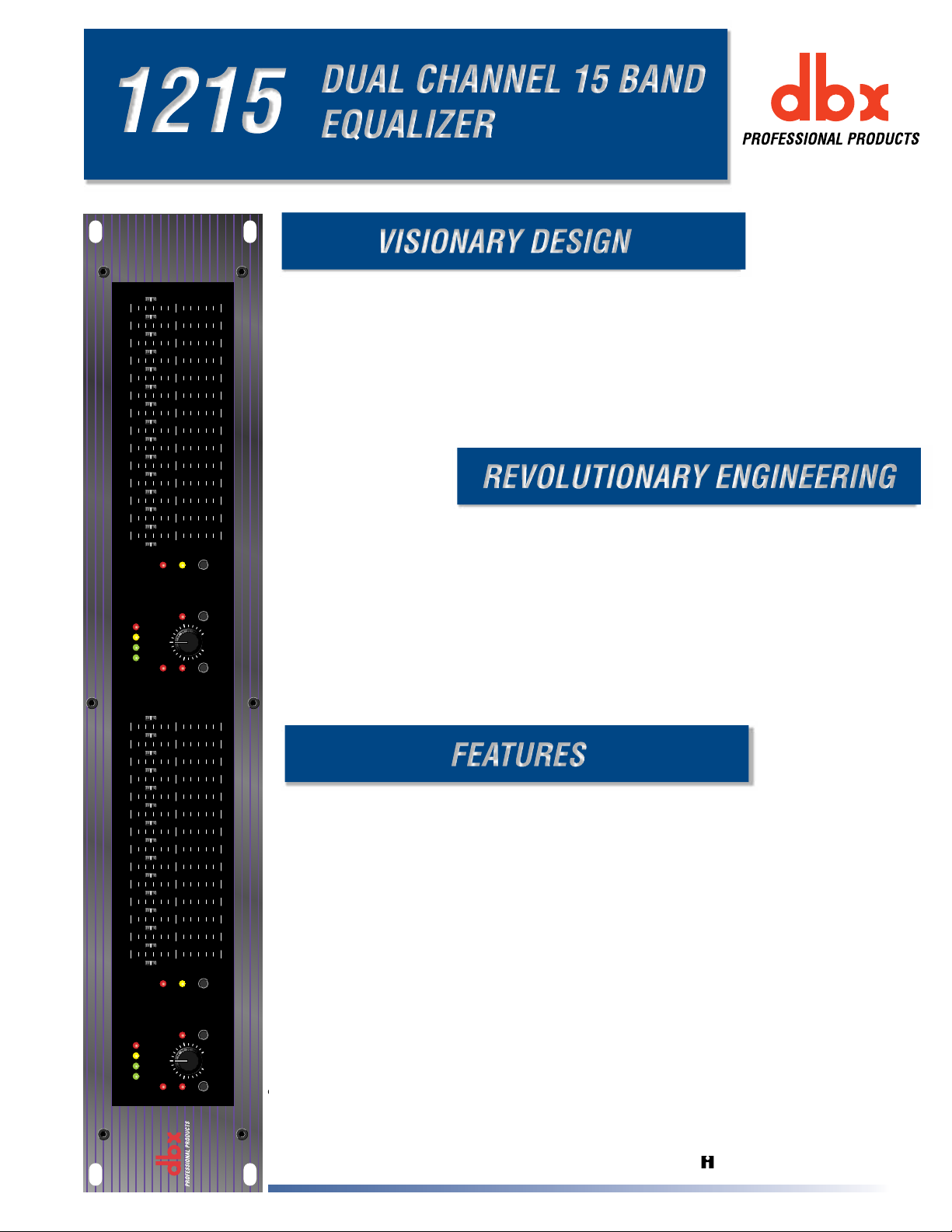
The dbx 12 Series were designed to meet the needs of the most demanding sound reinforcement
environments, while offering the simplicity of straightforward controls. The 1215 provides standard
features like dual channels, 15 2/3 octave bands, ISO frequency centers, +/-12 dB input gain range, and
switchable 40Hz/18 dB per octave low-cut filters, but also includes other thoughtful features. These
include 45 mm faders; selectable +/-6dB or +/-15dB boost/cut range for precise gain adjustments; XLR,
barrier strip, and 1/4'' TRS connectors for installation ease; balanced inputs and outputs for quiet
operation; and chassis/signal ground lift capabilities for quick hum isolation. The visionary design of
the dbx 12 Series makes your job easier.
The dbx 12 Series Equalizers were precision engineered to provide years of maintenance-free operation
in any application. The magnetically isolated transformer, electronically balanced/unbalanced inputs
and servo balanced/unbalanced outputs, RF-filtered inputs and outputs, and power-off hard-wire relay
bypass with 2 second power up delay were steps our engineers took to ensure compatibility for all
installations. Only the best components were utilized, yielding a 10Hz to 50kHz frequency response,
greater than 90dB SNR (ref +4dBu), less than 0.005% THD +Noise (1kHz at +4dBu), and interchannel
crosstalk of less than -80dB from 20Hz to 20kHz. All this attention to detail is contained in a 2U
steel/aluminum chassis. It’s no wonder that dbx has been a leader in the industry for over 25 years.
2231
DUAL CHANNEL 31 BAND
EQUALIZER WITH
TYPE III™ NOISE REDUCTION
18-1778-A 07/99
• Switchable Boost/Cut range between ±6dB and ±15dB
• Electronically balanced/unbalanced inputs
• Servo balanced/unbalanced outputs
• RF filtered inputs and outputs
• XLR, Barrier Strip, and 1/4" TRS connectors
• -12dB/+12dB input gain range
• 18dB/octave 40Hz Bessel low-cut filter
• Chassis/signal ground lift capability
• Internal power supply transformer
• Power-off hardwire relay bypass with 2-second power-up delay
1215
Graphic Equalizer
0
+15
25 40 63 100 160 250 400 16k10k6.3k4k630 1k 1.6k 2.5k
+6
+/-15
+18+100-10
0
OUTPUT
LEVEL (dBu)
CLIP
-15
0
-6
+/-6
RANGE
CUT
LOW
+12
dB
GAIN
INPUT
-12
EQ
BYPASS
0
+15
-15
25 40 63 100 160 250 400 16k10k6.3k4k630 1k 1.6k 2.5k
0
+6
+/-15
-6
+/-6
RANGE
CUT
+18+100-10
0
OUTPUT
LEVEL (dBu)
CLIP
LOW
+12
dB
GAIN
INPUT
-12
EQ
BYPASS
1215
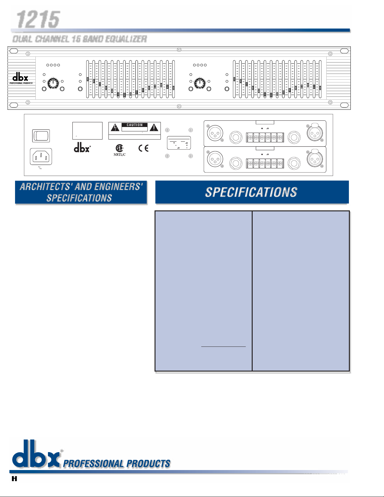
The graphic equalizer shall be a dual 15-band type with frequency centers
on standard ISO two-thirds octave frequencies ranging from 25Hz to
16kHz. The boost/cut ranges shall be switchable via recessed front panel
switches to either +/-6dB or +/-15dB and the selected range shall be
indicated on the front panel by either of two LEDs per channel. Low-noise
equalization sliders having a 45mm travel shall be utilized having center
detents at 0dB. The equalizer shall have front panel 41-detent rotary input
gain controls having a +/-12dB range. Bypassing the equalizer sections of
the signal path shall be accomplished via front-panel switches having
corresponding LEDs to indicate when each channel is bypassed. A 40Hz
low-cut Bessel filter per channel with 18dB/octave slope shall be insertable
in the signal path via front panel recessed switches with an LED to indicate
when the filter is active. Output levels shall be monitored on four-LED
peak-reading bar graphs calibrated to read -10, 0, +10, and +18dBu.
Electronically balanced/unbalanced inputs shall include 1/4" TRS, female
XLR, and screw terminal barrier strip, while servo-balanced/unbalanced
outputs shall include 1/4" TRS, male XLR, and screw terminal barrier strip
shared with the input. Acircuit/chassis ground lift jumper per channel shall
be strapped across circuit ground and chassis ground screw terminals and
shall be removable by the user. Inputs shall be electronically
balanced/unbalanced and RF filtered having a nominal input impedance
not less than 40kΩ balanced and 20kΩ unbalanced, and shall accept
maximum signal levels of not less than +21dBu. Outputs shall be servobalanced/unbalanced and RF filtered having a nominal output impedance
of not more than 200Ω balanced and 100Ω unbalanced, and shall be
capable of driving not less than +21dBu into 2kΩ or greater and not less
than +20dBm (into 600Ω) continuously.
Frequency response shall be better than 10Hz to 50kHz, +0.5/-3dB. Signalto-noise ratio shall be greater than 90dB, referenced to +4dBu. THD+Noise
shall be less than 0.005% with a 1kHz signal at +4dBu, while interchannel
crosstalk shall be lower than -80dB from 20Hz to 20kHz.
The internal power supply shall be constructed using a thermally-fused transformer mounted in a low hum orientation and shall
be magnetically isolated from equalizer circuitry by means of a mu-metal shield. The power cord shall be detachable from an
international standard IEC 320 power inlet receptacle. Unit shall be constructed to meet or exceed all applicable international
safety and regulatory agencies. Domestic unit shall be powered from 100VAC 50/60Hz, 120VAC 60Hz, while international unit
shall be powered from 230VAC 50/60Hz. Unit shall consume no more than 24W. Housing shall be of all steel/aluminum
construction and shall be rack-mountable in an IEC standard 19" rack and shall occupy a 2U (3.5") rack space. The unit shall be
a dbx 1215 Equalizer.
dbx engineers are constantly working to improve the quality of our products. Specifications are, therefore subject to change
without notice.
FOR MORE INFORMATION CONTACT:
dbx Professional Products
8760 S. Sandy Pkwy.
Sandy, Utah 84070
Phone (801) 568-7660
Fax (801) 568-7662
Int’l Fax (801) 568-7583
customer@dbxpro.com
http://www.dbxpro.com
A Harman International Company
586
Dual Vacuum Tube Preamp
TYPE IV™ Conversion System
704
Inputs
Connectors: 1/4" TRS, female XLR (pin 2
hot), and barrier terminal strip
Type: Electronically
balanced/unbalanced, RF
filtered
Impedance: Balanced 40kΩ, unbalanced
20kΩ
Max Input Level: >+21dBu balanced or
unbalanced
CMRR: >40dB, typically >55dB at
1kHz
Outputs
Connectors: 1/4" TRS, male XLR (pin 2
hot), and barrier terminal strip
Type: Impedance-
balanced/unbalanced, RF
filtered
Impedance: Balanced 200Ω, unbalanced
100Ω
Max Output Level: >+21dBu
balanced/unbalanced into
2kΩ or greater
>+18dBm
balanced/unbalanced (into
600Ω)
System Performance
Bandwidth: 20Hz to 20kHz, +0.5/-1dB
Frequency Response: <10Hz to >50kHz, +0.5/-3dB
+/-15dB range +/-6dB range
Dynamic Range: 109db 115db
Signal-to-Noise: 90db 97db
THD+Noise: <0.005%
Interchannel Crosstalk: <-80dB, 20Hz to 20kHz
Function Switches
EQ Bypass: Bypasses the graphic
equalizer section in the signal
path
Low Cut (recessed): Activates the 40Hz
18dB/octave Bessel highpass filter
Range (recessed): Selects either +/- 6dB or +/-
15dB slider boost/cut range
Indicators
Output Level: 4-LED bar graph (Green,
Green, Yellow, Red) at -10, 0,
+10, and +18dBu
EQ Bypass: 1 LED: red
Clip: 1 LED: red
Low Cut: 1 LED: red
+/-6dB: 1 LED: yellow
+/-15dB: 1 LED: red
Power Supply
Operating Voltage: 100VAC 50/60Hz, 120VAC
60Hz, 230VAC 50/60Hz
Power Consumption: 1215 24W; 1231 24W
Mains Connection: IEC receptacle
Physical
Dimensions: 1215: 3.5" H X 19" W X 7.9"
D (8.9cm x 48.3cm x 20.1cm)
1231: 5.25" H X 19" W X
7.9" D (13.4cm x 48.3cm x
20.1cm)
Weight: 1215: 8.5 lbs.
1231: 10.6 lbs.
Shipping Weight: 1215: 9.5 lbs.
1231: 11.6 lbs.
Note: Specifications subject to change.
DUAL CHANNEL 15 BAND EQUALIZER
CHANNEL ONE
CLIP
EQ
BYPASS
POWER
24 WATTS
100V 50/60Hz
120V 60Hz
OUTPUT
LEVEL (dBu)
-120+12
dB
INPUT
GAIN
+18+100-10
LOW
CUT
25 40 63 100 160 250 400 16k10k6.3k4k630 1k 1.6k 2.5k
+6
+/-15
+/-6
0
RANGE
-6
CAUTION: TO REDUCE
THE RISK OF FIRE REPLACE
ONLY WITH SAME TYPE FUSE.
ATTENTION: UTILISER
UN FUSIBLE DE RECHANGE DE
MEME TYPE.
PROFESSIONAL PRODUCTS
A HARMAN INTERNATIONAL
COMPANY
MODEL 1215
GRAPHIC EQUALIZER
ATTENTION: RISQUE DE CHOC ELECTRIQUE - NE PAS OUVRIR
WARNING: TO REDUCE THE RISK OF FIRE OR ELECTRIC
SHOCK DO NOT EXPOSE THIS EQUIPMENT TO RAIN OR MOISTURE
MANUFACTURED UNDER ONE OR MORE OF THE FOLLOWING
U.S. PATENTS: 4,234,804 4,316,107 4,329,598 4,331,931 4,377,792
4,403,199 4,409,500 4,425,551 4,434,380 4,454,433 4,471,324
4,473,793 OTHER PATENTS PENDING
RISK OF ELECTRIC SHOCK
DO NOT OPEN
CHANNEL TWO
+15
0
-15
CONNECTOR POLARITY
PHONE:
XLR:
TIP
PIN 1
RING
PIN 2
SLEEVE
PIN 3
+18+100-10
OUTPUT
LEVEL (dBu)
CLIP
-120+12
dB
LOW
EQ
INPUT
BYPASS
CUT
GAIN
OUTPUT INPUT
OUTPUT INPUT
25 40 63 100 160 250 400 16k10k6.3k4k630 1k 1.6k 2.5k
+6
+/-15
+/-6
0
RANGE
-6
®
+15
1215
0
Graphic Equalizer
-15
CHANNEL 1
OUTPUT
-
+
CHANNEL 2
OUTPUT
-
+
INPUTOUTPUT
INPUT
-
+
INPUTOUTPUT
INPUT
-
+
 Loading...