

Page 1

OPERATION MANUAL
MODE D’EMPLOI
BEDIENUNGSANLEITUNG
MODO DE EMPLEO
20 SERIES
EQUALIZER/LIMITER
with TYPE III NR
Page 2
WARNING FORYOUR PROTECTION
READ THESE INSTRUCTIONS:
KEEP THESE INSTRUCTIONS
HEED ALL WARNINGS
FOLLOW ALL INSTRUCTIONS
DO NOT USE THIS APPARATUS NEAR WATER
CLEAN ONLY WITH A DRY CLOTH.
DO NOT BLOCK ANY OF THE VENTILATION OPENINGS. INSTALL IN ACCORDANCE WITH THE MANU-
FACTURER’S INSTRUCTIONS.
DO NOT INSTALL NEAR ANY HEAT SOURCES SUCH AS RADIATORS, HEAT REGISTERS, STOVES, OR
OTHER APPARATUS (INCLUDING AMPLIFIERS) THAT PRODUCE HEAT.
ONLY USE ATTACHMENTS/ACCESSORIES SPECIFIED BY THE MANUFACTURER.
UNPLUG THIS APPARATUS DURING LIGHTNING STORMS OR WHEN UNUSED FOR LONG PERIODS OF
TIME.
Do not defeat the safety purpose of the polarized or grounding-type plug. A polarized plug has
two blades with one wider than the other. A grounding type plug has two blades and a third
grounding prong. The wide blade or third prong are provided for your safety. If the provided
plug does not fit your outlet, consult an electrician for replacement of the obsolete outlet.
Protect the power cord from being walked on or pinched particularly at plugs, convenience
receptacles, and the point where they exit from the apparatus.
Use only with the cart stand, tripod bracket, or table specified by the manufacture, or sold
with the apparatus. When a cart is used, use caution when moving the cart/apparatus combination to avoid injury from tip-over.
Refer all servicing to to qualified service personnel. Servicing is required when the apparatus has been damaged in any way, such as power-supply cord or plug is damaged, liquid has
been spilled or objects have fallen into the apparatus, the apparatus has been exposed to rain
or moisture, does not operate normally, or has been dropped.
POWER ON/OFF SWITCH: For products provided with a power switch, the power switch DOES
NOT break the connection from the mains.
MAINS DISCONNECT: The plug shall remain readily operable. For rack-mount or installation
where plug is not accessible, an all-pole mains switch with a contact separation of at least 3
mm in each pole shall be incorporated into the electrical installation of the rack or building.
FOR UNITS EQUIPPED WITH EXTERNALLY ACCESSIBLE FUSE RECEPTACLE: Replace fuse with
same type and rating only.
MULTIPLE-INPUT VOLTAGE: This equipment may require the use of a different line cord, attachment plug, or both, depending on the available power source at installation. Connect this equipment only to the power source indicated on the equipment rear panel. To reduce the risk of
fire or electric shock, refer servicing to qualified service personnel or equivalent.
This Equipment is intended for rack mount use only.
SAFETY INSTRUCTIONS
NOTICE FOR CUSTOMERS IF YOUR UNIT IS EQUIPPED WITH A POWER CORD.
WARNING:THISAPPLIANCEMUST BE EARTHED.
The cores in the mains lead are coloured in accordance with the following code:
GREEN and YELLOW - Earth BLUE - Neutral BROWN - Live
As colours of the cores in the mains lead of this appliance may not correspond with the coloured markings identifying the terminals in your plug, proceed as follows:
• The core which is coloured green and yellow must be connected to the terminal in the plug
marked with the letter E, or with the earth symbol, or coloured green, or green and yellow.
• The core which is coloured blue must be connected to the terminal marked N or coloured black.
• The core which is coloured brown must be connected to the terminal marked L or coloured red.
This equipment may require the use of a different line cord, attachment plug, or both, depending on the
available power source at installation. If the attachment plug needs to be changed, refer servicing to
qualified service personnel who should refer to the table below. The green/yellow wire shall be connected directly to the units chassis.
WARNING: If the ground is defeated, certain fault conditions in the unit or in the system to which it is connected can result in full line voltage between chassis and earth ground. Severe injury or death can then
result if the chassis and earth ground are touched simultaneously.
The symbols shown above are internationally accepted symbols that warn of potential hazards with
electrical products. The lightning flash with arrowpoint in an equilateral triangle means that there
are dangerous voltages present within the unit. The exclamation point in an equilateral triangle
indicates that it is necessary for the user to refer to the owner’s manual.
These symbols warn that there are no user serviceable parts inside the unit. Do not open the unit.
Do not attempt to service the unit yourself. Refer all servicing to qualified personnel. Opening the
chassis for any reason will void the manufacturer’s warranty. Do not get the unit wet. If liquid is
spilled on the unit, shut it off immediately and take it to a dealer for service. Disconnect the unit
during storms to prevent damage.
IMPORTANT SAFETY INSTRUCTIONS
Page 3
U.K. MAINS PLUG WARNING
A molded mains plug that has been cut off from the cord is unsafe.
Discard the mains plug at a suitable disposal facility. NEVER UNDER
ANY CIRCUMSTANCES SHOULD YOU INSERT A DAMAGED OR CUT
MAINS PLUG INTO A 13 AMP POWER SOCKET. Do not use the
mains plug without the fuse cover in place. Replacement fuse covers can be obtained from your local retailer. Replacement fuses are
13 amps and MUST be ASTA approved
to BS1362.
LITHIUM BATTERY
WARNING
CAUTION!
This product may contain a lithium battery. There is danger of
explosion if the battery is incorrectly replaced. Replace only
with an Eveready CR 2032 or equivalent. Make sure the battery is installed with the correct polarity. Discard used batteries according to manufacturer’s instructions.
ADVARSEL!
Lithiumbatteri - Eksplosjonsfare. Ved utskifting benyttes kun
batteri som anbefalt av apparatfabrikanten. Brukt batteri
returneres apparatleverandøren.
ADVARSEL!
Lithiumbatteri - Eksplosionsfare ved fejlagtig håndtering.
Udskiftning må kun ske med batteri av samme fabrikat og
type. Levér det brugte batteri tilbage til leverandøren.
VAROITUS!
Paristo voi räjähtää, jos se on virheellisesti asennettu. Vaihda
paristo ainoastaan laitevalmistajan suosittelemaan tyyppin.
Hävitä käytetty paristo valmistajan ohjeiden mukaisesti.
VARNING!
Explosionsfara vid felaktigt batteribyte. Använd samma batterityp eller en ekvivalent typ som rekommenderas av apparattillverkaren. Kassera använt batteri enligt fabrikantens instruktion.
IMPORTANT SAFETY INSTRUCTIONS
ELECTROMAGNETIC
COMPATIBILITY
This unit conforms to the Product
Specifications noted on the Declaration of
Conformity. Operation is subject to the following two conditions:
• this device may not cause harmful inter-
ference, and
• this device must accept any interference
received, including interference that may
cause undesired operation.
Operation of this unit within significant electromagnetic fields should be avoided.
• use only shielded interconnecting cables.
DECLARATION OF
CONFORMITY
Manufacturer’s Name: dbx Professional Products
Manufacturer’s Address: 8760 S. Sandy Parkway
Sandy, Utah 84070, USA
declares that the product:
Product name: dbx 2031, dbx2215 and dbx2231
Note: Product name may be suffixed by
the letters-EU.
Product option: None
conforms to the following Product Specifications:
Safety: IEC 60065 (1998)
EMC: EN 55013 (1990)
EN 55020 (1991)
Supplementary Information:
The product herewith complies with the requirements of the Low Voltage
Directive 73/23/EEC and the EMC Directive 89/336/EEC as amended by
Directive 93/68/EEC.
Vice-President of Engineering
8760 S. Sandy Parkway
Sandy, Utah 84070, USA
Date: July 1, 2003
European Contact: Your local dbx Sales and Service Office
or
Harman Music Group
8760 South Sandy Parkway
Sandy, Utah
84070 USA
Ph: (801) 566-8800
Fax: (801) 568-7583
Page 4

Page 5

MANUAL CONTENTS
ENGLISH . . . . . . . . . . . . . . . . . . . . . . . . . . . . . . . . . . . . . . . . . . . . . . . . . . . . . 2
F
RANÇAIS . . . . . . . . . . . . . . . . . . . . . . . . . . . . . . . . . . . . . . . . . . . . . . . . . . . . . 7
D
EUTSCH . . . . . . . . . . . . . . . . . . . . . . . . . . . . . . . . . . . . . . . . . . . . . . . . . . . . . 15
E
SPAÑOL . . . . . . . . . . . . . . . . . . . . . . . . . . . . . . . . . . . . . . . . . . . . . . . . . . . . . 23
ENGLISH CONTENTS
INTRODUCTION . . . . . . . . . . . . . . . . . . . . . . . . . . . . . . . . . . . . . . . . . . . . . . . . . . 2
I
NSPECTION . . . . . . . . . . . . . . . . . . . . . . . . . . . . . . . . . . . . . . . . . . . . . . . . . . . . 2
O
PERATING CONTROLS . . . . . . . . . . . . . . . . . . . . . . . . . . . . . . . . . . . . . . . . . . . . 2
C
ONNECTING THE EQ TO YOUR SYSTEM . . . . . . . . . . . . . . . . . . . . . . . . . . . . . . . 4
R
EAR PANEL DESCRIPTIONS . . . . . . . . . . . . . . . . . . . . . . . . . . . . . . . . . . . . . . . . 4
I
NSTALLATION CONSIDERATIONS . . . . . . . . . . . . . . . . . . . . . . . . . . . . . . . . . . . . . 5
O
PERATION AND APPLICATIONS NOTES . . . . . . . . . . . . . . . . . . . . . . . . . . . . . . . 6
TECHNICAL SUPPORT / FACTORY SERVICE . . . . . . . . . . . . . . . . . . . . . . . . . . . . . . 6
S
PECIFICATIONS . . . . . . . . . . . . . . . . . . . . . . . . . . . . . . . . . . . . . . . . . . . . . . . . . 32
B
LOCK DIAGRAM . . . . . . . . . . . . . . . . . . . . . . . . . . . . . . . . . . . . . . . . . . . . . . . . 33
OPERATION MANUAL
1
20 SERIES GRAPHIC EQUALIZERS
Page 6
INTRODUCTION
Congratulations on your purchase of a dbx graphic equalizer. All dbx graphic equalizers are high performance multifunctional units designed to deliver all the flexibility and power that professional users demand. We recommend that
you take a moment to read through this operation manual. It provides information that will assist you from system setup to EQ applications. The 20 Series Equalizers include the following features:
• Revolutionary dbx TYPE III™ Noise Reduction capable of restoring up to 20dB S/N ratio
• Proprietary patent-pending PeakPlus™ Limiter for system protection
• Switchable range between ±6dB and ±15dB
• Balanced inputs and outputs
• XLR, Barrier Strip, and 1/4” TRS connectors
• -12dB/+12dB input gain range
• 18dB/octave 40Hz Bessel Low-Cut filter
• Chassis/signal ground lift capability
• Internal power supply transformer
• Power-off hard-wire relay bypass with 2-second power-up delay
INSPECTION
Verify that the equalizer’s package contains the following:
• Equalizer unit matching serial number marked on package
• AC power cord
• Operation Manual
• Registration Card
• Four rack mount screws and washers
If any of these items are missing please contact dbx customer service at the number provided on the back cover of this
manual.
OPERATING CONTROLS
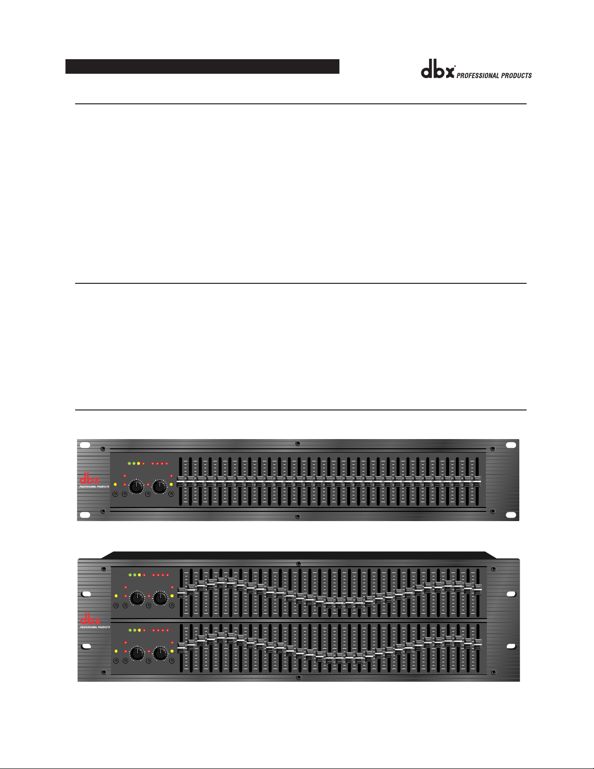
Front Panels
2031 - single channel 31 band graphic equalizer
2231 - dual channel 31 band graphic equalizer
2
OPERATION MANUAL
20 25 31.5 40 50 63 80 500400315250 1.6k1.25k1k800 5k4k3.15k2.5k 16k12.5k10k8k6.3k 20k2k630100 125 160 200
1
3610+18+100-10
+6
GAIN
OUTPUT
REDUCTION (dB)
LEVEL (dBu)
CLIP
-120+12
dB
EQ
TYPE
III
INPUT
BYPASS
NR
GAIN
OUTPUT
LEVEL (dBu)
CLIP
-120+12
dB
INPUT
EQ
TYPE
III
NR
GAIN
BYPASS
OUTPUT
LEVEL (dBu)
CLIP
-120+12
dB
EQ
TYPE
III
INPUT
BYPASS
NR
GAIN
+/-15
+15+10
+/-6
0
+20+5
0 OFF
dBu
RANGE
LOW
PeakPlus
CUT
THRESHOLD
-6
13610+18+100-10
+6
GAIN
REDUCTION (dB)
+/-15
+15+10
+/-6
0
+20+5
0 OFF
dBu
RANGE
LOW
PeakPlus
CUT
THRESHOLD
-6
20 25 31.5 40 50 63 80 500400315250 1.6k1.25k1k800 5k4k3.15k2.5k 16k12.5k10k8k6.3k 20k2k630100 125 160 200
13610+18+100-10
+6
GAIN
REDUCTION (dB)
+/-15
+15+10
+/-6
0
+20+5
0 OFF
dBu
RANGE
LOW
PeakPlus
CUT
THRESHOLD
-6
+15
2031
0
Equalizer/Limiter
with TYPE
III
NR
-15
+15
0
-15
2231
Equalizer/Limiter
+15
with TYPE
III
NR
0
-15
Page 7

2215 - dual channel 15 band graphic equalizer
Input Gain Control: This control sets the signal level to the equalizer. It is capable of -12dB to +12dB of gain. Its
effect is apparent by viewing the OUTPUT LEVEL BAR GRAPH.
EQ Bypass: This switch removes the graphic equalizer section from the signal path. (See Block diagram on Page
32.) The BYPASS switch does not, however, affect the INPUT GAIN, or LOW CUT filters.
EQ Bypass LED: This red LED lights when the EQ is in bypass mode. Note that bypass mode only effects the
graphic equalizer section of the 20 Series EQs. The INPUT GAIN and and LOW CUT controls remain unaffected
when the EQ is bypassed.
Boost/Cut Range Selection Switch and LEDs: This switch selects which of the two boost/cut ranges the equalizer
will use, either ±6dB or ±15dB. The red LED lights when the ±15dB range is selected, and the yellow LED lights
when the ±6dB range is selected. Note that the BOOST/CUT switch is slightly recessed. This is to prevent accidental activation of the switch, possibly causing damage to other sound system components.
Output Level Bar Graph: These four LEDs indicate output level of the equalizer. The red LED is 3dB below clipping and is marked as +18dBu. It monitors the level at the output of the equalizer after all other processing, including the limiter.
Clip LED: This LED lights whenever any internal signal level reaches 3dB below clipping which may occur when
any of the following happen: 1) the input signal is “hotter” than +22dBu, 2) excessive gain is applied by the input
gain control, or 3) excessive boost is applied using the frequency sliders.
Gain Reduction Meter: These four LEDs indicate the amount of gain reduction being induced by the setting of the
PeakPlus™ LIMITER THRESHOLD control as the signal level from the graphic EQ section exceeds this limiter
threshold setting.
PeakPlus™ Limiter Threshold Control: This control engages the PeakPlus™ limiter. It sets the threshold level at
which ∞:1 gain reduction will begin to occur. Its design is borrowed from the patent-pending PeakStopPlus™
Limiter found on the popular dbx 1066 and 1046 compressor/limiters. It is capable of a range of 0dBu through
“OFF” (+24dBu). When the threshold control is set to “OFF”, the limiter is effectively disabled, and no gain reduction will occur.
dbx Type III™ Noise Reduction Switch: The switch engages the dbx Type III™ Noise Reduction circuit within
the EQ.
dbx Type III™ Noise Reduction LED: The yellow LED lights when the dbx Type III™ Noise Reduction circuit is
activated via the NOISE REDUCTION Switch.
Frequency Band Slider Controls: Each one of these slider potentiometers will boost or cut at its noted frequency
by ±6dB or ±15dB, depending upon the position of the BOOST/CUT RANGE switch. When all the sliders are in
the center detented position the output of the equalizer is flat. The frequency band centers of the 2031 and the 2231
are marked at 1/3rd of an octave intervals on ISO standard spacings, while the frequency band centers of the 2215
are marked at 2/3rds of an octave intervals on ISO standard spacings.
Low Cut Enable Switch: The LOW-CUT switch inserts or removes the 18dB/octave 40Hz Bessel low-cut filter
from the signal path. When the LOW-CUT switch is pushed in, the LOW-CUT filter is IN the audio path.
OPERATION MANUAL
3
20 SERIES GRAPHIC EQUALIZERS
25 40 63 100 160 250 400 16k10k6.3k4k630 1k 1.6k 2.5k
1
3610+18+100-10
LEVEL (dBu)
CLIP
-120+12
dB
EQ
TYPE
III
INPUT
BYPASS
NR
GAIN
+/-15
+15+10
+/-6
0
+20+5
0 OFF
dBu
RANGE
LOW
PeakPlus
CUT
THRESHOLD
-6
+6
GAIN
OUTPUT
REDUCTION (dB)
+15
-15
OUTPUT
LEVEL (dBu)
CLIP
0
-120+12
dB
LOW
EQ
TYPE
III
INPUT
CUT
BYPASS
NR
GAIN
25 40 63 100 160 250 400 16k10k6.3k4k630 1k 1.6k 2.5k
1
3610+18+100-10
+6
GAIN
REDUCTION (dB)
+/-15
+15+10
+/-6
0
+20+5
0 OFF
dBu
RANGE
PeakPlus
THRESHOLD
-6
+15
0
Equalizer/Limiter
with TYPE
-15
2215
III
NR
Page 8
CONNECTING THE EQ TO YOUR SYSTEM
The 20 Series Equalizers have balanced inputs and outputs that can be used with any balanced or unbalanced linelevel device. For more specific information about cabling possibilities, please refer to the section entitled
Installation Considerations, Page 5.
To connect the equalizer to your sound system refer to the following steps:
• Turn off all equipment before making connections.
• Mount equalizer in a standard-width rack.
Install the EQs in a rack with the rack screws provided. It can be mounted above or below anything that does
not generate excessive heat. Ambient temperatures should not exceed 113° F (45°C) when equipment is in use.
Although the unit’s chassis is shielded against radio frequency and electromagnetic interference, extremely
high fields of RF and EMI should be avoided.
• Make audio connections via XLR, barrier strip, or 1/4” TRS jacks (according to application needs)
All three types of connectors for the inputs and outputs can be used for balanced or unbalanced connections.
The use of more than one connector at a time for the inputs could unbalance balanced lines, cause phase cancellation, short a conductor to ground, or cause damage to other equipment connected to the equalizer. More than
one output may be used simultaneously as long as the combined parallel load is greater than 600Ω.
• Select the operating range with the BOOST/CUT RANGE SELECTION switch
Note: Be sure to reduce audio levels at the power amplifiers when changing the setting of this switch as it may generate an audible transient.
• Apply power to the equalizer
Connect the AC power cord to the AC power receptacle on the back of the equalizer. Route the AC power cord
to a convenient power outlet away from audio lines. The unit may be turned on and off from the rear panel
power switch or a master equipment power switch. Since the 20 Series Equalizers consume a relatively small
amount of power, the units may be left on continuously.
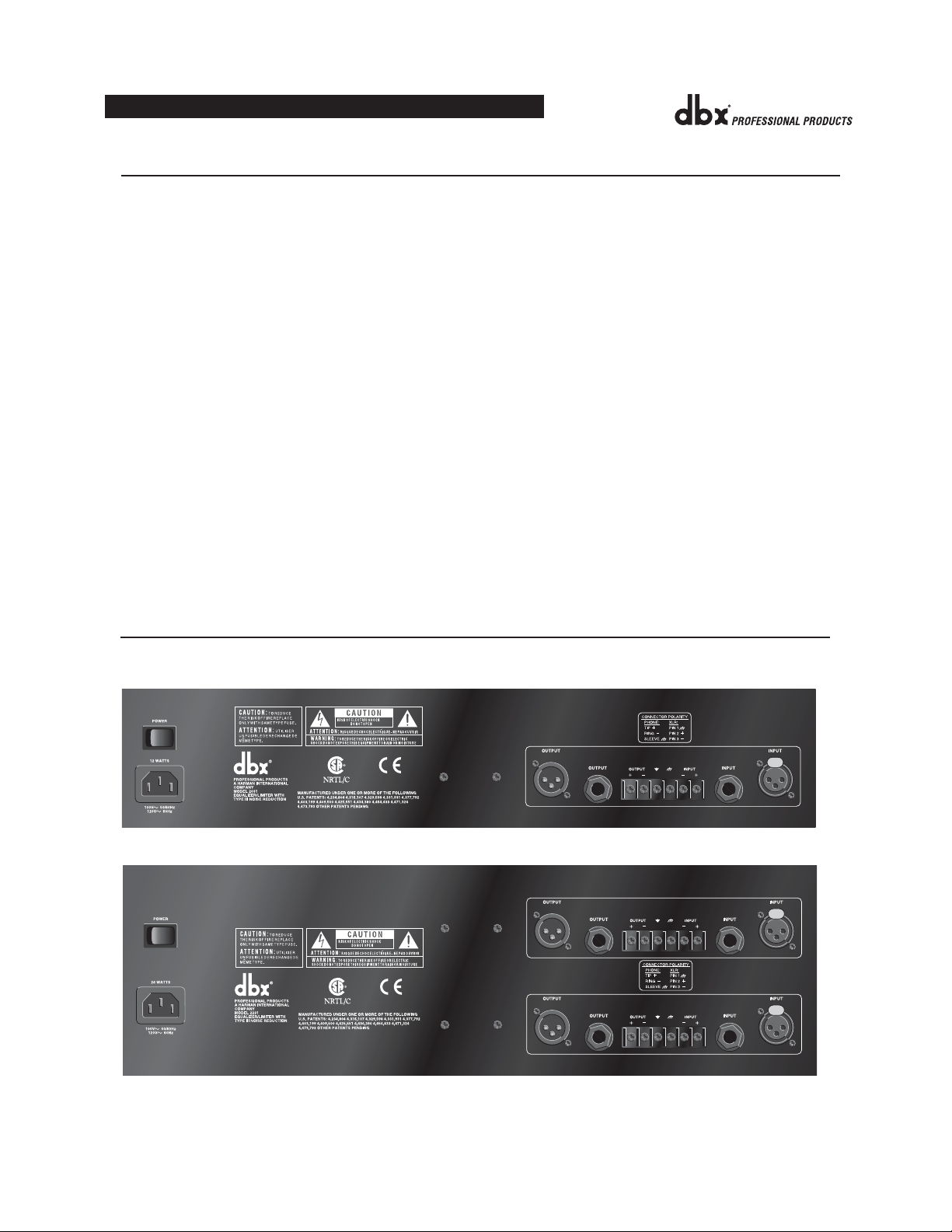
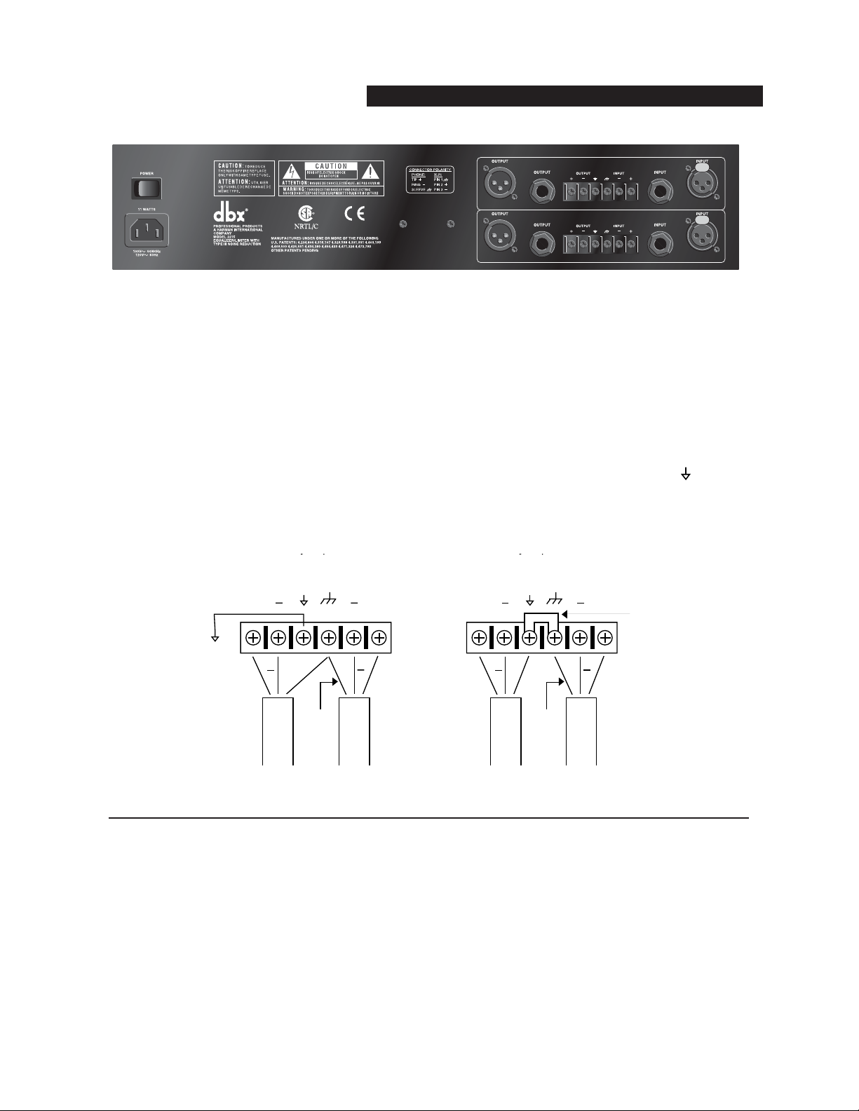
REAR PANEL DESCRIPTIONS
Rear Panels
2031 - single channel 31 band graphic equalizer
2231 - dual channel 31 band graphic equalizer
4
OPERATION MANUAL
Page 9
2215 - dual channel 15 band graphic equalizer
Power Cord Receptacle: Connects AC power to the equalizer.
Power Switch: Switches the power on and off. Always make audio connections with the power switch in the OFF
position.
Input Connectors: Three types of input connectors are provided for input connections: female locking XLR type
connectors, 1/4” tip-ring-sleeve phone jack connectors, and a barrier strip. The maximum input level that the equalizer can accept is +22dBu (ref: 0.775Vrms).
Output Connectors: Three types of output connectors are provided for output connections: male XLR type connectors, 1/4” tip-ring-sleeve phone jack connectors and a barrier strip.
Chassis Ground Lift Strap: By removing the jumper connecting the two screws on the barrier strip, the chassis
ground is separated from the circuit ground of the equalizer. This is sometimes necessary to prevent “ground loops”
in a sound system. When lifting the ground strap, you must make a connection from the circuit ground ( ) terminal
to some other ground point in your audio system in order for the equalizer to function properly.
INSTALLATION CONSIDERATIONS
Hookups and Cabling: The 20 Series Equalizers are designed for nominal +4dBu levels. The equalizers can be
used with either balanced or unbalanced sources, and the outputs can be used with either balanced or unbalanced
loads, provided the proper cabling is used.
A balanced line is defined as two-conductor shielded cable with the two center conductors carrying the same signal
but of opposite polarity when referenced to ground. An unbalanced line is generally a single-conductor shielded
cable with the center conductor carrying the signal and the shield at ground potential.
Input Cable Configurations: The equalizer has an input impedance of 40kΩ balanced and 20kΩ unbalanced. This
makes the 20 Series Equalizers’ audio inputs suitable for use with virtually any low source impedance (under 2kΩ).
Output Cable Configurations: The equalizer’s output is capable of driving a 600Ω load to +18dBu. For maximum
hum rejection with a balanced source, avoid common grounding at the equalizer’s inputs and outputs. Most balanced (3-conductor) cables have the shield connected at both ends. This can result in ground loops which cause
hum. If hum persists try disconnecting the shield on one or more of the cables in the system, preferably at the input
of a device, not at the output.
OPERATION MANUAL
5
20 SERIES GRAPHIC EQUALIZERS
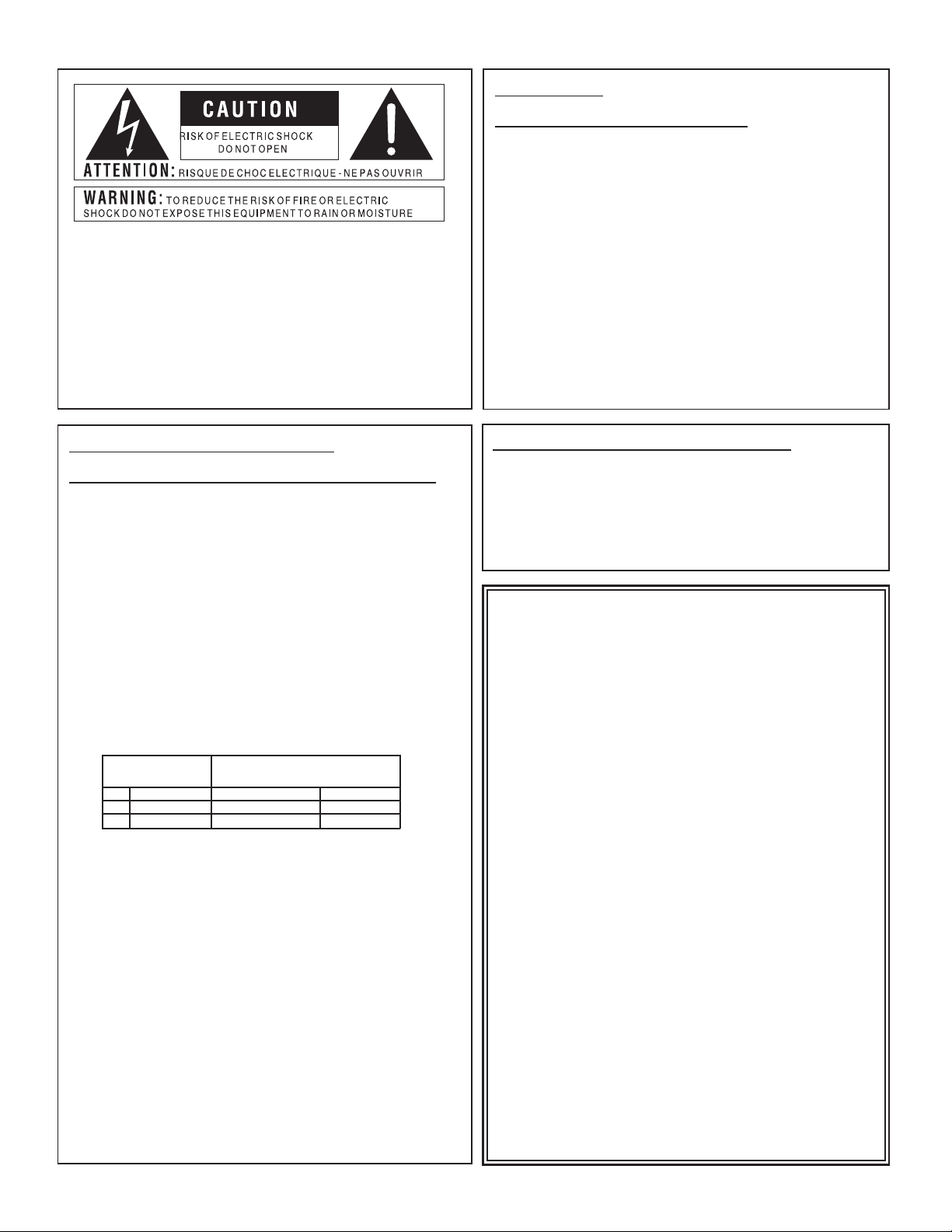
Wiring Connections With Ground
WIRING CONNECTIONS WITH GROUND
Without Jumper in Place With Jumper in Place
circuit
ground
++
chassis
ground
++
circuit
ground
chassis
ground
jumper
to system
ground
Output
Cable
optional
+
Input
Cable
++
Output
Cable
optional
+
Input
Cable
Page 10

OPERATION AND APPLICATION NOTES
The dbx 20 Series Graphic Equalizers are useful audio signal processing tools in situations where precise frequency
control is required across the audible frequency spectrum.
When used with an audio spectrum analyzer the EQs can tune any acoustical environment -- from the studio to the
concert hall -- to stop ringing, increase clarity, and flatten the overall frequency response of the environment. A
real-time spectrum analyzer or other types of audio environment analyzers are very useful in determining the
amount of equalization needed.
Insert the graphic equalizer between the signal source (usually a mixer) and the power amplifiers (or the crossover if
there is one). Adjust the level and equalization as required to yield the desired system response. The long throw
faders of the EQs allow very precise settings of the equalization for accurate equalization curves.
For optimum signal-to-noise response, the gain structure of the sound system must be properly set up. Each component of the sound system should be set at its nominal operating level, starting with the first element in the system,
usually a mixing console. Each element should be run at its nominal operating level in order to take advantage of
the maximum signal-to-noise properties of that element. Loudspeaker amplifiers, as the last element in the chain,
should be set only as loud as necessary, in order to avoid inducing unnecessary noise into the system.
All active equalizers, by nature of design, add noise when boosting or cutting that can easily degrade the otherwise
acceptable signal-to-noise ratio of a sound system. Drastic equalization can result in a loss of 20dB or more signalto-noise. dbx Type III™ Noise Reduction was engineered specifically for applications such as this. It provides up to
20dB of noise reduction, thus restoring the dynamic range necessary for even the most demanding professional
sound systems. The combination of proper wiring, proper gain structure and TYPE III™ Noise Reduction should
render your sound system virtually noise free.
TECHNICAL SUPPORT / FACTORY SERVICE
The dbx 20 Series EQs are all solid-state products with components chosen for high performance and excellent reliability. Each unit has been tested and burned-in at the factory. No adjustment of any type should be required
throughout the life of the unit.
If circumstances arise which necessitate repair, we recommend that your EQ be returned to the factory. This can
only be done by receiving a RETURN AUTHORIZATION number from dbx customer service.
If you require technical support contact Customer Service. Be prepared to accurately describe the problem. Know
the serial number of your unit (printed on a sticker attached to the chassis of the unit).
Contact information is printed on the back cover of this manual.
6
OPERATION MANUAL
Page 11

FRANÇAIS
OPERATION MANUAL
7
20 SERIES GRAPHIC EQUALIZERS
Page 12
8
ATTENTION
POUR VOTRE PROTECTION, LISEZ CE QUI SUIT :
EAU ET MOISISSURE : L’appareil ne doit pas être utilisé près d’une source
d’eau (par exemple près d’une baignoire, cuvette, évier, dans un sous-sol
humide, ou près d’une piscine, etc.). Faire attention à ce qu’aucun objet ou liquide ne pénètre dans l’appareil par certaines ouvertures.
ALIMENTATION : Veiller à respecter la tension secteur correspondante.
MASSE ET POLARITE : Prendre soin de respecter la polarité et la mise à la
masse.
CORDON SECTEUR : Le cordon secteur doit être placé de manière à éviter
d’être coincé par d’autres appareils et qu’on ne puisse pas marcher dessus, vérifier bien le cordon à son embase et à sa prise.
DEPANNAGE : Pour éviter le risque d’incendie et de choc électrique, l’utilisateur
ne doit pas tenter de dépanner l’appareil en dehors des instructions indiquées
dans le manuel d’utilisation. En cas de panne, s’adresser à un technicien qualifié.
POUR LES APPAREILS EQUIPES D’UN FUSIBLE ACCESSIBLE DE
L’EXTERIEUR : Remplacer le fusible par un fusible de même type et de même
valeu
r.
INSTRUCTIONS DE SECURITE
NOTE CONCERNANT LES APPAREILS MUNIS D’UN CORDON SECTEUR
ATTENTION : L’APPAREIL DOIT ETRE RELIE A LA TERRE
Les conducteurs du câble secteur sont identifiés comme suit :
Vert/Jaune Terre
Bleu Neutre
Brun Phase
Si la couleur des conducteurs du câble secteur de cet appareil ne correspond pas à la couleur des conducteurs de la prise, procéder comme
suit :
• Le conducteur vert/jaune doit être relié au fil vert ou vert/jaune ou marqué avec la lettre E, ou avec le symbole Terre.
• Le conducteur bleu doit être relié au fil noir ou marqué avec la lettre N.
• Le conducteur brun doit être relié au fil rouge ou marqué avec la lettre
L.
CONDUCTEUR COULEUR
NORMAL AUTRE
L PHASE BRUN NOIR
N NEUTRE BLEU BLANC
E TERRE JAUNE/VERT VERT
ATTENTION : si la mise à la terre est absente, certains problèmes peuvent apparaître dans l’appareil ou le système auquel il est connecté en
cas de tension importante entre le châssis et la terre. De sérieux risques
de blessures graves et même de mort existent en cas de contact simultané de la masse châssis et de la terre.
COMPATIBILITE ELECTROMAGNETIQUE
L’appareil est conforme aux normes indiquées sur la Déclaration de conformité.
• cet appareil ne provoquera pas de parasites nuisibles
• cet appareil supporte tout parasite, même un parasite qui pourrait
causer un dysfonctionnement.
L’utilisation de cet appareil dans un champ électromagnétique important doit être
évitée.
Les symboles montrés ci-dessus sont internationaux et concernent les appareils
électriques. Le symbole de gauche vous avertit de la présence d’une tension dangereuse, suffisante pour provoquer un choc électrique. Le symbole de droite vous
avertit que les instructions de fonctionnement sont importantes. Prenez soin de lire
le manuel.
Ces symboles indiquent qu’aucune pièce n’est accessible à l’intérieur de l’appareil.
Ne pas ouvrir l’appareil. Ne pas essayer de dépanner. S’adresser à un technicien
qualifié. L’ouverture de l’appareil sans raison annulera la garantie constructeur. Ne
pas mouiller l’appareil. Si un liquide est renversé dessus, éteindre immédiatement
l’appareil et le porter chez le distributeur pour dépannage. Débrancher l’appareil en cas d’orage pour éviter des dommages.
DECLARATION DE CONFORMITE
Nom fabricant : dbx Professional Products
Adresse fabricant : 8760 S. Sandy Parkway
Sandy, Utah 84070, USA
déclare que le produit
dbx 2031, 2231, 2215
est conforme aux spécifications suivantes :
Safety:
IEC 60065 (1998)
IEC65 (1985) avec Amendements 1, 2, 3
EMC: EN 55013 (1990)
EN 55020 (1991)
Informations complémentaires :
Le produit est conforme aux directives 73/23/EEC et 89/336/EEC modifié par la Directive 93/68/EEC.
dbx Professional Products
President of dbx
8760 S. Sandy Parkway
Sandy, Utah 84070, USA
July 1, 2003
Contacter votre distributeur
or Harman Music Group
8760 South Sandy Parkway Sandy, Utah 84070 USA
Ph: (801) 566-8800 Fax:(801) 568-7583
Page 13

OPERATION MANUAL
9
20 SERIES GRAPHIC EQUALIZERS
TABLE DES MATIERES
INTRODUCTION . . . . . . . . . . . . . . . . . . . . . . . . . . . . . . . . . . . . . . . . . . . . . . . . . . 10
V
ÉRIFICATION . . . . . . . . . . . . . . . . . . . . . . . . . . . . . . . . . . . . . . . . . . . . . . . . . . . 10
RÉGLAGES . . . . . . . . . . . . . . . . . . . . . . . . . . . . . . . . . . . . . . . . . . . . . . . . . . . . . 10
R
ACCORDEMENT DU CORRECTEUR À VOTRE SYSTEME . . . . . . . . . . . . . . . . . . . . . 12
P
ANNEAU ARRIERE . . . . . . . . . . . . . . . . . . . . . . . . . . . . . . . . . . . . . . . . . . . . . . . 12
C
ONSIDERATIONS SUR L’INSTALLATION . . . . . . . . . . . . . . . . . . . . . . . . . . . . . . . . 13
U
TILISATION ET NOTES DE FONCTIONNEMENT . . . . . . . . . . . . . . . . . . . . . . . . . . . 14
C
ARACTÉRISTIQUES TECHNIQUES . . . . . . . . . . . . . . . . . . . . . . . . . . . . . . . . . . . . 31
S
YNOPTIQUE . . . . . . . . . . . . . . . . . . . . . . . . . . . . . . . . . . . . . . . . . . . . . . . . . . . . 32
Page 14

INTRODUCTION
Nous vous félicitons d’avoir choisi le correcteur graphique dbx. Tous les correcteurs graphiques dbx sont des
appareils de haute performance et fonctionnels, conçus pour des utilisateurs professionnels. Nous vous invitons à
lire ce manuel pour tirer le meilleur profit de votre appareil. Les correcteurs de la série 20 affichent les caractéristiques suivantes :
• Réduction de bruit révolutionnaire dbx TYPE III™ capable de restaurer un rapport signal/bruit
de 20 dB
• Système exclusif de limitation dbx PeakPlus™ pour une protection accrue
• Sélection de la plage d’efficacité (entre ±6 dB et ±15 dB)
• Entrées et sorties symétriques
• Connexions par XLR, bornier et Jacks 6,35 mm
• Plage de gain d’entrée de -12 dB/+12 dB
• Filtre coupe-bas 18 dB/octave à 40 Hz de type Bessel
• Possibilité de découplage de la terre et du châssis
• Transformateur d’alimentation intégré
• By-pass de mise hors tension par relais et retard de 2 sec. à la mise sous tension
VÉRIFICATION
Assurez-vous que l’emballage contient les articles suivants :
• Correcteur graphique (avec numéro de série identique à celui porté sur l’emballage)
• Cordon d’alimentation
• Mode d’emploi
• Quatre vis de montage en rack avec rondelles
RÉGLAGES
Faces avant
2031 - Correcteur graphique monophonique 31 bandes
2231 - Double correcteur graphique 31 bandes
10
OPERATION MANUAL
20 25 31.5 40 50 63 80 500400315250 1.6k1.25k1k800 5k4k3.15k2.5k 16k12.5k10k8k6.3k 20k2k630100 125 160 200
1
3610+18+100-10
+6
GAIN
OUTPUT
REDUCTION (dB)
LEVEL (dBu)
CLIP
-120+12
dB
EQ
TYPE
III
INPUT
BYPASS
NR
GAIN
OUTPUT
LEVEL (dBu)
CLIP
-120+12
dB
EQ
TYPE
III
INPUT
BYPASS
NR
GAIN
OUTPUT
LEVEL (dBu)
CLIP
-120+12
dB
EQ
TYPE
III
INPUT
BYPASS
NR
GAIN
LOW
CUT
LOW
CUT
LOW
CUT
+/-15
+15+10
+/-6
0
+20+5
0 OFF
dBu
RANGE
PeakPlus
THRESHOLD
-6
13610+18+100-10
+6
GAIN
REDUCTION (dB)
+/-15
+15+10
+/-6
0
+20+5
0 OFF
dBu
RANGE
PeakPlus
THRESHOLD
-6
20 25 31.5 40 50 63 80 500400315250 1.6k1.25k1k800 5k4k3.15k2.5k 16k12.5k10k8k6.3k 20k2k630100 125 160 200
13610+18+100-10
+6
GAIN
REDUCTION (dB)
+/-15
+15+10
+/-6
0
+20+5
0 OFF
dBu
RANGE
PeakPlus
THRESHOLD
-6
+15
2031
0
Equalizer/Limiter
with TYPE
III
-15
+15
0
-15
2231
Equalizer/Limiter
+15
with TYPE
III
0
-15
NR
NR
Page 15

2215 - Double correcteur graphique 15 bandes
Réglage du gain d’entrée (Input Gain) : Ce réglage adapte le niveau du signal d’entrée au correcteur. La plage de
gain varie de -12 dB à +12 dB. Son action est visualisable sur le Vumètre OUTPUT LEVEL.
EQ Bypass : Ce bouton laisse passer le signal sans correction (voir synoptique en page 32). Le bouton BYPASS
n’affecte pas le gain d’entrée ou les filtres coupe-bas.
Led EQ Bypass : Cette Led rouge s’allume lorsque le correcteur est en mode ”bypass”. Notez que le mode
”bypass” n’affecte que la section correcteur graphique. Les réglages ”INPUT GAIN” et ”LOW CUT” restent sans
effet lorsque le correcteur est placé en mode ”bypass”.
Sélecteur ”Range” et Leds : Ce bouton définit l’amplitude de l’atténuation/accentuation du correcteur : ±6 dB ou
±15 dB. La Led rouge s’allume pour vous indiquer la sélection de la plage ±15 dB, la Led jaune vous indiquant la
sélection de la plage ±6 dB. Notez que le bouton ”Range” est placé légèrement en retrait pour éviter toute fausse
manipulation dangereuse pour vos matériels audio.
VUmètre Output Level : Ces quatre Leds indiquent le niveau de sortie du correcteur. La Led rouge s’allume à 3
dB en dessous de l’écrêtage (marquée +18 dBu). Le VUmètre affiche le niveau du signal en sortie du correcteur, en
aval de tous les traitements, limitation comprise.
Led de saturation Clip : Cette LED s’allume dès qu’un signal interne atteint 3 dB en dessous de la saturation.
Celle-ci peut survenir dans les cas suivants : 1) le signal d’entrée est supérieur à +22 dBu,
2) le réglage de gain d’entrée est excessif, 3) il y a une accentuation excessive du signal sur les tirettes de fréquence.
VUmètre Gain Reduction : Ces quatre Leds indiquent la réduction de gain appliquée au signal par le réglage de
seuil THRESHOLD du limiteur PeakPlus™ dès que le niveau du signal en sortie du correcteur excède ce seuil.
Réglage de seuil du limiteur PeakPlus™ : Ce réglage active le limiteur PeakPlus™. Il définit le seuil au-delà
duquel une réduction de ∞:1 sera appliquée. Sa conception est issue du circuit de limitation breveté PeakStopPlus™
que l’on trouve sur les compresseurs/limiteurs dbx 1066 et 1046. Son efficacité varie sur une plage allant de 0 dBu à
“OFF” (+24 dBu). Lorsque le réglage de seuil est sur “OFF”, le limiteur est inopérant, aucune réduction de gain
n’étant appliquée.
Bouton de réduction de bruit dbx Type III™ : Ce bouton active le circuit de réduction de bruit dbx Type III™.
Led du réducteur de bruit dbx Type III™ : La Led jaune s’allume lorsque le circuit de réduction de bruit dbx
Type III™ est activé par le bouton TYPE III NR.
Tirettes de fréquence : Chacune de ces tirettes atténue ou accentue le signal à la fréquence spécifiée de ±6 dB ou
±15 dB, en fonction de la position du bouton RANGE. Lorsque toutes les tirettes sont en position centrale (crantée),
la réponse du correcteur est plate. Les fréquences ajustables sur les modèles 2031 et 2231 sont espacées d’1/3
d’octave (valeur ISO), alors que les fréquences ajustables du modèle 2215 sont espacées de 2/3 d’octave (valeur
ISO).
Bouton Low Cut : Le bouton LOW-CUT active ou désactive le filtre coupe-bas 40 Hz de 18 dB/octave de type
Bessel. Lorsque le bouton LOW-CUT est enclenché, le filtre coupe-bas devient actif.
OPERATION MANUAL
11
20 SERIES GRAPHIC EQUALIZERS
25 40 63 100 160 250 400 16k10k6.3k4k630 1k 1.6k 2.5k
1
3610+18+100-10
LEVEL (dBu)
CLIP
-120+12
dB
EQ
TYPE
III
INPUT
BYPASS
NR
GAIN
+/-15
+15+10
+/-6
0
+20+5
0 OFF
dBu
RANGE
LOW
PeakPlus
CUT
THRESHOLD
-6
+6
GAIN
OUTPUT
REDUCTION (dB)
+15
-15
OUTPUT
LEVEL (dBu)
CLIP
0
-120+12
dB
LOW
EQ
TYPE
III
INPUT
CUT
BYPASS
NR
GAIN
25 40 63 100 160 250 400 16k10k6.3k4k630 1k 1.6k 2.5k
1
3610+18+100-10
+6
GAIN
REDUCTION (dB)
+/-15
+15+10
+/-6
0
+20+5
0 OFF
dBu
RANGE
PeakPlus
THRESHOLD
-6
+15
0
Equalizer/Limiter
with TYPE
-15
2215
III
NR
Page 16

RACCORDEMENT DU CORRECTEUR À VOTRE SYSTEME
Les correcteurs de la série 20 sont équipés de connecteurs entrée/sortie symétriques, mais peuvent être utilisés avec
n’importe quel appareil à connexions symétriques ou asymétriques travaillant à niveau ligne. Pour obtenir de plus
amples renseignements sur les possibilités de câblage, consultez le chapitre Considérations sur l’installation en
page 13.
Pour raccorder le correcteur à votre système audio, suivez les étapes ci-dessous :
• Avant tout branchement, éteignez tous vos appareils.
• Installez le correcteur dans un rack standard.
Montez le correcteur à l’aide des vis fournies. II peut être installé sur ou sous tout appareil ne dégageant pas de
chaleur excessive. La température ambiante ne doit pas dépasser 45°C lors de l’utilisation. Malgré que le boîtier
soit blindé contre les fréquences radio et autres interférences électromagnétiques, évitez la proximité d’appareils
pouvant être sources de ce type d’interférences.
• Réalisez les connexions audio par les XLR, bornier, ou Jacks 6,35 mm (en fonction des besoins de l’application).
Ces trois types de connexions d’entrée et de sortie peuvent être utilisés indifféremment pour des raccordements
symétriques ou asymétriques. L’utilisation simultanée de plus d’un connecteur d’entrée pourrait asymétriser la
connexion, causer des annulations de phase, court-circuiter deux conducteurs, voire endommager les appareils
raccordés au correcteur. Vous pouvez utiliser simultanément plusieurs sorties tant que le résultat de la charge
parallèle ne dépasse pas 600Ω.
• Sélectionnez la plage d’atténuation/accentuation avec le bouton RANGE
Note : Veillez à réduire le niveau de vos amplificateurs avant de modifier ce réglage car il est source de transitoire audible.
• Mettez le correcteur sous tension
Connectez le cordon secteur au dos du correcteur. Raccordez la prise au réseau par une prise de puissance suffisante éloignée des câbles audio. Vous pouvez maintenant allumer ou éteindre le correcteur par l’interrupteur
situé en face arrière, ou par un interrupteur général déporté. Etant donné la faible consommation des correcteurs
de la série 20, ceux-ci peuvent rester constamment sous tension.
PANNEAU ARRIERE
Panneaux arrières
2031 - Correcteur graphique monophonique 31 bandes
2231 - Correcteur graphique à deux canaux 31 bandes
12
OPERATION MANUAL
Page 17

2215 - Correcteur graphique à deux canaux 15 bandes
Prise châssis secteur : Permet le raccordement du cordon secteur du correcteur.
Interrupteur Marche/Arrêt : Permet d’allumer ou d’éteindre le correcteur. Veillez à toujours réaliser les raccorde-
ments audio lorsque le correcteur est éteint.
Connexions d’entrée : Il existe trois types de connecteurs disponibles pour les entrées : XLR femelle à verrouil-
lage, Jack stéréo 6,35 mm et bornier. Le niveau d’entrée maximal supporté par le correcteur est de +22 dBu
(0.775 Vrms).
Connexions de sortie : Il y a trois types de connecteurs disponibles pour les sorties : XLR mâle, Jack stéréo
6,35 mm, et bornier.
Strap de découplage de masse : En supprimant le strap du bornier, la masse du châssis devient indépendante de la
masse électrique du correcteur. Cette opération est parfois nécessaire pour résoudre les problèmes de boucle de
masse. En découplant les masses par la suppression du strap, vous devez raccorder la masse du circuit à un autre
point de masse de votre chaîne audio, de sorte que le correcteur fonctionne normalement.
CONSIDÉRATIONS SUR L’INSTALLATION
Raccordements et câblage : Les correcteurs de la série 20 sont conçus pour travailler à un niveau nominal de
+4 dBu. Les correcteurs d’entrée et de sortie peuvent être indifféremment connectés à des sources symétriques ou
asymétriques, à condition d’effectuer un câblage correct.
Une ligne symétrique se caractérise par la présence de deux conducteurs portant le même signal, mais de polarité
inverse par rapport à la masse. Une ligne asymétrique se caractérise par la présence d’un seul conducteur blindé
transportant le signal, le blindage transportant la masse électrique.
Configuration des câbles d’entrée : L’impédance d’entrée du correcteur est de 40 kΩ symétrique et de 20 kΩ
asymétrique. Cela rend les entrées des correcteurs de la série 20 parfaitement compatibles avec quasiment toutes les
sources basse impédance (inférieures à 2 kΩ).
Configuration des câbles de sortie : Le niveau maximal des sorties des correcteurs sous 600 Ω est de +18 dBu.
OPERATION MANUAL
13
20 SERIES GRAPHIC EQUALIZERS
Câblages
Sans strap
Avec strap
Masse
châssis
Masse
châssis
Masse
circuit
Masse
circuit
Strap
Vers masse
commune
au système
Facultatif
Câble
d’entrée
Câble
de sor-
tie
Câble
de sor-
tie
Facultatif
Câble
d’entrée
WIRING CONNECTIONS WITH GROUND
to system
ground
Without Jumper in Place With Jumper in Place
circuit
ground
chassis
ground
++
+
Output
Cable
optional
Input
Cable
++
++
Output
Cable
circuit
ground
optional
chassis
ground
+
Input
Cable
jumper
Page 18

Pour un rejet optimal des ronflements, évitez de raccorder les masses du signal d’entrée et du signal de sortie du
correcteur. La plupart des câbles symétriques (3-conducteurs) ont leur masse connectée aux deux extrémités. Ceci
peut induire des boucles de masse et des ronflements. Si les ronflements persistent, essayez de déconnecter la masse
d’un ou plusieurs câbles de la chaîne audio, de préférence du côté entrée et non du côté sortie de l’appareil.
UTILISATION ET NOTES DE FONCTIONNEMENT
Les correcteurs graphiques dbx de la série 20 sont des outils de traitement du signal utilisés lorsqu’un contôle précis
de la fréquence s’avère nécessaire sur toute l’étendue du spectre sonore.
Utilisés conjointement avec un analyseur de spectre, les correcteurs peuvent permettre d’adapter un système audio à
l’environnement acoustique (du studio à la salle de concert) évitant ainsi les résonnances, d’améliorer la clarté et
d’aplanir la réponse globale en fréquence de l’environnement. L’analyseur de spectre en temps réel est un outil très
utile pour déterminer la correction à appliquer.
Insérez le correcteur graphique entre le signal source (généralement la console) et les amplificateurs de puissance
(ou le filtre actif si c’est le cas). Ajustez le niveau et la correction nécessaire pour obtenir la courbe de réponse
recherchée. Les potentiomètres à course longue des correcteurs permettent des réglages précis de la courbe de
réponse.
Pour obtenir un rapport signal/bruit optimisé, les réglages de gain des éléments de la chaîne audio doivent être correctement effectués. Chaque élément de cette chaîne doit être réglé sur son niveau de fonctionnement nominal en
commençant par le premier maillon, en général la console de mixage. Chaque élément doit travailler à son niveau
nominal pour obtenir un rapport signal/bruit optimal de cet élément. Les amplificateurs de puissance, derniers éléments de la chaîne, doivent être réglés à puissance maximale disponible pour éviter toute génération de bruit dans la
chaîne.
Tous les correcteurs actifs, de par leur nature, induisent du bruit lors de l’atténuation ou de l’amplification des bandes de fréquence, qui altère le rapport signal/bruit du système audio pourtant déjà optimisé. Une correction excessive peut induire une perte de 20 dB ou plus du rapport signal/bruit. Le réducteur de bruit dbx Type III™ a été spécialement conçu pour de telles applications. Ce circuit améliore la réduction de bruit à hauteur de 20 dB, rétablissant
ainsi la plage dynamique requise par les systèmes audio professionnels les plus exigeants. La conjonction d’un
câblage adapté, d’une bonne gestion des gains associée à l’utilisation de la réduction de gain dbx TYPE III™ vous
permettra de supprimer tout bruit de fond de votre système audio.
14
OPERATION MANUAL
Page 19

DEUTSCH
OPERATION MANUAL
15
20 SERIES GRAPHIC EQUALIZERS
Page 20

16
WARNUNG
BEACHTEN SIE ZU IHRER EIGENEN SICHERHEIT BITTE FOLGENDES:
WASSER UND FEUCHTIGKEIT: Benutzen Sie das Gerät nicht in feuchter Umgebung
(z.B. in der Nähe von Badewannen, Waschbecken, Spülbecken, Waschtrögen, in feuchten Kellerräumen oder neben einem Schwimmbecken). Achten Sie darauf, daß keine
Gegenstände oder Flüssigkeiten in das Innere des Gerätes gelangen.
NETZGERÄT: Schliessen Sie das Gerät nur an das in der Bedienungsanleitung bzw. am
Gerät angegebene Netzgerät an.
SCHUTZERDE UND PHASENUMSCHALTER: Achten Sie darauf, den Erdanschluss des
Gerätes nicht zu unterbrechen und den Phasenumschalter nicht zu deaktivieren.
SCHUTZ DES NETZKABELS: Verlegen Sie alle Netzkabel immer so, dass möglichst niemand darauf treten und die Netzkabel durch darauf oder daneben gestellte Gegenstände
nicht gequetscht werden können. Dies gilt besonders in der unmittelbaren Umgebung der
Netzstecker, Netzsteckdosen und des Kabelaustritts am jeweiligen Gerät.
SERVICE: Um Brände oder elektrische Schläge zu vermeiden, versuchen Sie nicht,
andere Servicearbeiten als die in dieser Bedienungsanleitung beschriebenen am Gerät
durchzuführen. Wenden Sie sich für diese Arbeiten an einen qualifizierten Techniker.
GERÄTE MIT VON AUSSEN ZUGÄNGLICHEM SICHERUNGSHALTER: Ersetzen Sie
durchgebrannte Sicherungen nur durch Sicherungen desselben Typs.
NETZSPANNUNGEN: Je nach Art des am Einsatzort vorhandenen Netzanschlusses
kann ein anderer Netzstecker, ein anderes Netzkabel oder beides erforderlich sein.
Schliessen Sie das Gerät nur an die an der Rückseite des Gerätes angegebene
Netzspannung an. Um Brände oder elektrische Schläge zu vermeiden, wenden Sie sich
für Reparaturen an einen qualifizierten Techniker.
SICHERHEITSHINWEISE
WICHTIGER HINWEIS BEI GERÄTEN MIT NETZKABEL:
ACHTUNG: DIESES GERÄT MUSS MIT EINER SCHUTZERDUNG VERSE-
HEN SEIN.
Die Adern des Netzkabels sind wie folgt farbcodiert:
GRÜN/GELB = Erde BLAU = Nulleiter BRAUN= Phase
Da die Farben der Adern des Netzkabels nicht unbedingt mit den
Farbmarkierungen der Kontaktstifte in Ihrem Netzstecker übereinstimmen,
gehen Sie bitte wie folgt vor:
• Schliessen Sie die grün/gelbe Ader an den mit dem Erdsymbol, dem
Buchstaben "E", einem grünen oder grün/gelben Farbpunkt gekennzeichneten Kontaktstift an.
• Schliessen Sie die blaue Ader an den mit dem Buchstaben "N" oder
einem schwarzen Farbpunkt gekennzeichneten Kontakstift an.
• Schliessen Sie die braune Ader an den mit dem Buchstaben "L" oder
einem roten Farbpunkt gekennzeichneten Kontaktstift an.
Je nach Art des am Einsatzort vorhandenen Netzanschlusses wird möglicherweise ein anderes Netzkabel bzw. ein anderer Netzstecker oder beides erforderlich sein. Der Netzstecker darf nur von einem qualifizierten Techniker anhand
untenstehender Tabelle getauscht werden. Dabei ist die grün/gelbe Ader direkt
mit Gehäusemasse zu verbinden.
WARNUNG: Bei unterbrochener Schutzerdung können bestimmte Fehler im
Gerät oder in der Anlage, an die das Gerät angeschlossen ist, dazu führen, daß
zwischen Gehäusemasse und Erde die volle Netzspannung anliegt. Das gleichzeitige Berühren des Gehäuses und eines Erdpunkts kann in diesem Fall zu
schweren Verletzungen oder zum Tod führen.
ADER FARBE
Standard Alt.
L PHASE BRAUN SCHWARZ
N NULLLEITER BLAU WEISS
E SCHUTZERDE GRÜN/GELB GRÜN
NETZSTECKER
Verwenden Sie aus Sicherheitsgründen vom Netzkabel abgeschnittene mitgespritzte Netzstecker nie weiter, sondern entsorgen Sie sie entsprechend den
lokalen Entsorgungsvorschriften.
Schließen Sie beschädigte Netzstecker niemals an eine Netzsteckdose an
.
Die obigen Symbole sind international üblich und dienen als Gefahrenhinweise bei
Elektrogeräten. Das Blitzsymbol links oben weist auf gefährliche Spannungen im Gerät
hin. Das Rufzeichen rechts oben weist auf wichtige Punkte hin, die unbedingt in der
Bedienungsanleitung nachzulesen sind.
Diese Symbole bedeuten auch, daß sich im Gerät keine vom Anwender reparierbaren
Teile befinden. Öffnen Sie das Gerät auf keinen Fall und versuchen Sie nicht, es selbst
zu reparieren. Lassen Sie Reparaturen ausschließlich von einem qualifizierten
Techniker durchführen. Wenn Sie das Gerät öffnen, erlischt automatisch die Garantie
des Herstellers. Machen Sie das Gerät nicht naß. Wenn dennoch eine Flüssigkeit auf
oder in das Gerät gelangt, schalten Sie es sofort aus und bringen Sie es zu einem
Händler zur Überprüfung. Ziehen Sie bei Gewittern zum Schutz vor Beschädigungen
des Geräts das Netzkabel ab.
ELEKTROMAGNETISCHE VERTRÄGLICHKEIT
Dieses Gerät entspricht den in der Konformitätserklärung angeführten Spezifikationen.
Voraussetzung für den Betrieb des Gerätes ist die Erfüllung folgender Bedingungen:
• Das Gerät darf keine schädliche Störstrahlung abgeben.
• Das Gerät darf durch empfangene Störstrahlung einschliesslich
Störstrahlungen, die Betriebsstörungen hervorrufen können, nicht
beschädigt werden.
Der Betrieb des Geräts in starken elektromagnetischen Feldern ist zu vermeiden.
• Verwenden Sie ausschliesslich geschirmte Verbindungskabel.
KONFORMITÄTSERKLÄRUNG
Hersteller: dbx Professional Products
Adresse des Herstellers: 8760 S. Sandy Parkway
Sandy, Utah 84070, USA
erklärt, dass das Produkt: dbx 2031, 2231, 2215
folgende Produktnormen erfüllt:
EMV:
IEC 60065 (1998)
Sicherheit EN 60065 (1993)
IEC65 (1987) mit Abänderungen 1, 2, 3
Zusatzinformation:
Das Produkt erfüllt hiermit die Bestimmungen der EMV-Richtlinie 89/336/EWG (1989), in der durch Richtlinie
93/68/EWG (1993) abgeänderten Form.
dbx Professional Products
Vice President of Engineering
8760 S. Sandy Parkway
Sandy, Utah 84070, USA
1. July 2003
Kontaktperson Europa: Ihr dbx-Händler bzw. -Servicestelle oder
International Sales Office or Harman Music Group
8760 South Sandy Parkway Sandy, Utah 84070 USA
Ph: (801) 566-8800 Fax:(801) 568-7583
GARANTIEBEDINGUNGEN
Wir gewähren 1 Jahr Garantie ab Verkaufsdatum
auf nachweisbare Material- und Fabrikationsfehler
(ausgenommen externe Netzgeräte). Der
Garantieanspruch erlischt bei unsachgemässer
Handhabung, elektrischer oder mechanischer
Beschädigung durch missbräuchliche Anwendung
sowie bei unsachgemässer Reparatur durch nichtautorisierte Werkstätten. Zur Inanspruchnahme der
angeführten Garantieleistungen ist der Nachweis
des Kaufes (ordentliche Rechnung des Verkäufers)
erforderlich. Transport- und Portospesen, welche
aus der Einsendung des Gerätes zur
Garantiereparatur erwachsen, können von dbx nicht
übernommen werden, das Risiko der Zusendung
trägt der Kunde. Die Garantie wird ausschliesslich
für den Erstkäufer geleistet.
Page 21

INHALT
EINLEITUNG . . . . . . . . . . . . . . . . . . . . . . . . . . . . . . . . . . . . . . . . . . . . . . . . . . . . 18
K
ONTROLLE . . . . . . . . . . . . . . . . . . . . . . . . . . . . . . . . . . . . . . . . . . . . . . . . . . . 18
B
EDIENELEMENTE . . . . . . . . . . . . . . . . . . . . . . . . . . . . . . . . . . . . . . . . . . . . . . . 18
ANSCHLIESSEN DES EQUALIZERS AN IHRE ANLAGE . . . . . . . . . . . . . . . . . . . . . . . 20
RÜCKSEITE . . . . . . . . . . . . . . . . . . . . . . . . . . . . . . . . . . . . . . . . . . . . . . . . . . . . . 20
A
NSCHLUSSHINWEISE . . . . . . . . . . . . . . . . . . . . . . . . . . . . . . . . . . . . . . . . . . . . . 21
BEDIENUNGS- UND ANWENDUNGSHINWEISE . . . . . . . . . . . . . . . . . . . . . . . . . . . . 22
S
ERVICE UND KUNDENDIENST . . . . . . . . . . . . . . . . . . . . . . . . . . . . . . . . . . . . . . . 22
TECHNISCHE DATEN . . . . . . . . . . . . . . . . . . . . . . . . . . . . . . . . . . . . . . . . . . . . . . 31
B
LOCKSCHALTBILD . . . . . . . . . . . . . . . . . . . . . . . . . . . . . . . . . . . . . . . . . . . . . . . 32
OPERATION MANUAL
17
20 SERIES GRAPHIC EQUALIZERS
Page 22

18
OPERATION MANUAL
EINLEITUNG
Wir danken Ihnen, daß Sie sich für einen Equalizer von dbx entschieden haben. Die graphischen Equalizer von dbx
sind multifunktionale Geräte mit der Flexibilität und Leistungsfähigkeit, die für professionelle Anwendungen
erforderlich sind. Bitte nehmen Sie sich etwas Zeit, die Bedienungsanleitung durchzulesen. Sie finden darin wichtige
Hinweise vom Anschließen des Gerätes bis hin zu Anwendungsbeispielen. Die Hauptmerkmale der Serie 20 sind:
• dbx TYPE III™ Rauschunterdrückung zum Aufholen von bis zu 20 dB Rauschabstand
• PeakPlus™ Limiter (Patent angemeldet) zum Schutz Ihrer Anlage
• Regelbereich zwischen ±6dB und ±12dB umschaltbar
• Symmetrische Ein- und Ausgänge
• Anschlüsse an XLR- und Stereoklinkenbuchsen sowie Klemmleisten
• Eingangsverstärkung von -12dB bis +12dB einstellbar
• Bessel-Trittschallfilter mit 18dB/Oktave bei 40Hz
• Signalmasse von Gehäusemasse trennbar
• eingebauter Netztrafo
• Automatischer Bypass bei Abschalten bzw. Netzausfall über Relais mit 2 s Einschaltverzögerung.
KONTROLLE
Kontrollieren Sie bitte, ob der Karton, in dem Ihr Equalizer geliefert wurde, folgende Teile enthält:
• Equalizer (entsprechend der Seriennummer am Karton)
• Netzkabel
• Bedienungsanleitung
• Registrierungskarte
• 4 Stk. Befestigungsschrauben und Unterlegscheiben
Falls etwas fehlt, wenden Sie sich bitte an Ihre AKG-Vertretung (s. letzte Seite).
BEDIENELEMENTE
Frontplatte
Einkanaliger 31-bandiger graphischer Equalizer 2031
Zweikanaliger 31-bandiger graphischer Equalizer 2231
20 25 31.5 40 50 63 80 500400315250 1.6k1.25k1k800 5k4k3.15k2.5k 16k12.5k10k8k6.3k 20k2k630100 125 160 200
1
3610+18+100-10
+6
GAIN
OUTPUT
REDUCTION (dB)
LEVEL (dBu)
CLIP
-120+12
dB
EQ
TYPE
III
INPUT
BYPASS
NR
GAIN
OUTPUT
LEVEL (dBu)
CLIP
-120+12
dB
EQ
TYPE
III
INPUT
BYPASS
NR
GAIN
OUTPUT
LEVEL (dBu)
CLIP
-120+12
dB
EQ
TYPE
III
INPUT
BYPASS
NR
GAIN
LOW
CUT
LOW
CUT
LOW
CUT
+/-15
+15+10
+/-6
0
+20+5
0 OFF
dBu
RANGE
PeakPlus
THRESHOLD
-6
13610+18+100-10
+6
GAIN
REDUCTION (dB)
+/-15
+15+10
+/-6
0
+20+5
0 OFF
dBu
RANGE
PeakPlus
THRESHOLD
-6
20 25 31.5 40 50 63 80 500400315250 1.6k1.25k1k800 5k4k3.15k2.5k 16k12.5k10k8k6.3k 20k2k630100 125 160 200
13610+18+100-10
+6
GAIN
REDUCTION (dB)
+/-15
+15+10
+/-6
0
+20+5
0 OFF
dBu
RANGE
PeakPlus
THRESHOLD
-6
+15
2031
0
Equalizer/Limiter
with TYPE
III
NR
-15
+15
0
-15
2231
Equalizer/Limiter
+15
with TYPE
III
NR
0
-15
Page 23

Zweikanaliger 15-bandiger graphischer Equalizer 2215
INPUT GAIN-Regler: Stellt den Signalpegel für die Equalizerschaltung ein. Der Regelbereich beträgt -12dB bis
+12dB Verstärkung. Die Wirkung der jeweiligen Einstellung wird durch die OUTPUT LEVEL-LEDs angezeigt.
EQ BYPASS-Taste: Mit dieser Taste können Sie sämtliche Schieberegler wegschalten (siehe Blockschaltbild auf
Seite X). Die INPUT GAIN- und LOW CUT-Regler bleiben jedoch wirksam.
EQ BYPASS-LED: Zeigt durch Leuchten an, dass der Equalizerteil abgeschaltet ist. Beachten Sie, dass bei allen
Equalizern der Serie 20 die EQ BYPASS-Taste nur auf den graphischen Equalizerteil wirkt. Die INPUT GAIN- und
LOW CUT-Regler bleiben auch bei gedrückter EQ- BYPASS-Taste wirksam.
RANGE-Taste und -LEDs: Schaltet den Regelbereich der Schieberegler zwischen ±6dB und ±15dB um. Wenn
Sie auf ±15dB schalten, leuchtet die rote LED, bei ±6dB die gelbe. Beachten Sie, dass die RANGE-Taste leicht
versenkt angebracht ist. Dies macht es schwerer. die Taste unabsichtlich zu drücken, was unter Umständen zu
Schäden an anderen Geräten Ihrer Anlage führen könnte.
OUTPUT LEVEL-LEDs: Diese 4 LEDs zeigen den Ausgangspegel des Equalizers an. Die rote LED mit der
Bezeichnung ”+18dBu” leuchtet bei 3dB unter Clipping auf. Angezeigt wird der Ausgangspegel nach sämtlichen
Prozessorschaltungen, also auch nach dem Limiter.
CLIP-LED: Diese LED leuchtet auf, solbald der interne Signalpegel an irgendeiner Stelle auf 3dB unter Clipping
steigt. Dies kann in folgenden Fällen geschehen: 1) das Eingangssignal ist stärker als +22dBu, 2) der INPUT GAINRegler ist zu hoch aufgedreht oder 3) die Frequenzband-Schieberegler sind zu weit aufgezogen.
GAIN REDUCTION-Anzeige: Diese 4 LEDs zeigen das Ausmass der Signaldämpfung an, die erfolgt, wenn der
Ausgangssignalpegel des Equalizerteils den mit dem LIMITER THRESHOLD-Regler des PeakPlus™ Limiters
eingestellten Wert übersteigt.
PeakPlus THRESHOLD-Regler: Schaltet den PeakPlus™ Limiter zu. Der Regler stellt den Pegel ein, ab dem das
Signal im Verhältnis ∞:1 gedämpft wird. Die Schaltung entspricht im wesentlichen dem von den
Kompressor/Limitern dbx 1066 und 1046 her bekannten PeakStopPlus™ Limiter (Pat. ang.). Der Regelumfang
reicht von 0dBu bis “OFF” (+24dBu). In Stellung ”OFF” ist der Limiter praktisch abgeschaltet und es erfolgt keine
Signaldämpfung.
TYPE III NR-Taste: Schaltet die dbx Type III™ Rauschunterdrückung des Equalizers ein und aus.
TYPE III NR-LED: Diese gelbe LED leuchtet, solange die dbx Type III™ Rauschunterdrückung eingeschaltet ist
(TYPE III NR-Taste gedrückt).
Frequenzband-Schieberegler: Mit den Schiebereglern können Sie die jeweils angegebene Frequenz je nach
Stellung der RANGE-Taste um ±6dB oder ±15dB anheben oder absenken. Wenn sich alle Schieberegler in der
gerasteten Mittelstellung befinden, ist der Frequenzgang des Ausgangssignals linear. Der Abstand zwischen den
Mittenfrequenzen der Frequenzbänder des dbx 2031 und 2231 beträgt jeweils 1/3 Oktave nach ISO. Der Abstand
zwischen den Mittenfrequenzen des dbx 2215 beträgt jeweils 2/3 Oktaven nach ISO.
LOW CUT-TASTE: Die LOW CUT-Taste schaltet das Bessel-Trittschallfilter mit 18dB/Oktave bei 40Hz in den
Signalweg ein und aus dem Signalweg heraus. Bei hineingedrückter LOW CUT-Taste ist das Filer eingeschaltet.
OPERATION MANUAL
19
20 SERIES GRAPHIC EQUALIZERS
25 40 63 100 160 250 400 16k10k6.3k4k630 1k 1.6k 2.5k
1
3610+18+100-10
LEVEL (dBu)
CLIP
-120+12
dB
EQ
TYPE
III
INPUT
BYPASS
NR
GAIN
+/-15
+15+10
+/-6
0
+20+5
0 OFF
dBu
RANGE
LOW
PeakPlus
CUT
THRESHOLD
-6
+6
GAIN
OUTPUT
REDUCTION (dB)
+15
-15
OUTPUT
LEVEL (dBu)
CLIP
0
-120+12
dB
LOW
EQ
TYPE
III
INPUT
CUT
BYPASS
NR
GAIN
25 40 63 100 160 250 400 16k10k6.3k4k630 1k 1.6k 2.5k
1
3610+18+100-10
+6
GAIN
REDUCTION (dB)
+/-15
+15+10
+/-6
0
+20+5
0 OFF
dBu
RANGE
PeakPlus
THRESHOLD
-6
+15
0
Equalizer/Limiter
with TYPE
-15
2215
III
NR
Page 24

ANSCHLIESSEN DES EQUALIZERS AN IHRE ANLAGE
Die Equalizer der Serie 20 besitzen symmetrische Ein- und Ausgänge und können daher zusammen mit jedem LinePegel-Gerät eingesetzt werden. Nähere Informationen zur Verkabelung finden Sie im Kapitel
"Anschlusshinweise" auf Seite 21.
Bei der Verkabelung beachten Sie bitte:
• Schalten Sie immer alle Geräte aus, bevor Sie eine Kabelverbindung herstellen.
• Montieren Sie den Equalizer in einem 19"-Rack (optional).
Montieren Sie den Equalizer mit den mitgelieferten Befestigungsschrauben. Sie können das Gerät oberhalb
oder unterhalb von anderen Geräten montieren, die nicht zuviel Wärme abgeben. Bei eingeschalteten Geräten
darf die Umgebungstemperatur 45°C nicht übersteigen. Das Gehäuse ist zwar gegen HF- und
Brummeinstreuungen abgeschirmt, stellen Sie das Gerät aber trotzdem nicht in der Nähe extrem starker HFoder elektromagnetischer Felder auf.
• Stellen Sie die gewünschten Audioverbindungen mittels XLR- oder Stereoklinkensteckern bzw. über die
Klemmleisten her (je nach Anwendung).
An alle drei Arten von Ein- und Ausgängen können Sie sowohl symmetrische als auch asymmetrische Geräte
anschliessen. Wenn Sie mehrere Anschlüsse desselben Ein- oder Ausgangs gleichzeitig benützen, können
dadurch symmetrische Verbindungen asymmetrisch werden, Phasenauslöschungen entstehen, das Signal gegen
Masse kurzgeschlossen oder das angeschlossene Gerät beschädigt werden. Wenn Sie mehr als einen
Ausgangsanschluss gleichzeitig belegen, achten Sie darauf, dass die Gesamt-Lastimpedanz der parallel
angeschlossenen Geräte mehr als 600Ω beträgt.
• Stellen Sie mit der RANGE-Taste den gewünschten Regelbereich der Schieberegler ein.
Anmerkung: Da beim Drücken dieser Taste ein Schaltknack entstehen kann, reduzieren Sie vorher unbedingt die Lautstärke der Endverstärker.
• Schalten Sie den Equalizer ein.
Schließen Sie das Netzkabel an die Netzanschlussbuchse an der Rückseite des Gerätes an. Führen Sie das
Netzkabel zu einer gut zugänglichen Netzsteckdose, in deren Nähe sich keine Audioleitungen befinden. Sie
können den Equalizer mit dem Netzschalter an der Frontplatte oder einem Anlagenhauptschalter ein- und ausschalten.
RÜCKSEITE
Anschlüsse und Bedienelemente
Einkanaliger 31-bandiger graphischer Equalizer 2031
20
OPERATION MANUAL
Page 25

Zweikanaliger 15-bandiger graphischer Equalizer 2215
Netzanschlussbuchse: IEC-Kaltgerätebuchse zum Anschluß des mitgelieferten Netzkabels.
POWER-Schalter: Schaltet das Gerät ein und aus. Schalten Sie das Gerät immer aus, bevor Sie
Audioverbindungen herstellen.
INPUT-Anschlüsse: Pro Eingang stehen drei verschiedene Anschlüsse zur Verfügung: verriegelbare XLR-
Buchsen, 6,3-mm-Stereoklinkenbuchsen und eine Klemmleiste. Der maximal zulässige Eingangspegel für den
Equalizer beträgt +22dBu (bezogen auf 0,775Veff.)
OUTPUT-Anschlüsse: Pro Ausgang stehen drei verschiedene Anschlüsse zur Verfügung: verriegelbare XLRBuchsen, 6,3-mm-Stereoklinkenbuchsen und eine Klemmleiste.
GROUND LIFT-Drahtbrücke: Durch Entfernen der Drahtbrücke zwischen den beiden Schraubklemmen können
Sie die Gehäusemasse von der Signalmasse des Equalizers trennen. Dies ist manchmal notwendig, um in einer
Beschallungsanlage "Erdschleifen" zu verhindern. In diesem Fall müssen Sie den Signalmasseanschluss ( ) mit
einem anderen Erdanschluss innerhalb Ihrer Anlage verbinden, damit Ihr Equalizer einwandfrei funktioniert.
ANSCHLUSSHINWEISE
Verbindungen und Kabel: Die Equalizer der Serie 20 sind für einen Nennpegel von +4dBu ausgelegt.
Vorausgesetzt, die Kabel sind richtig beschaltet, können Sie die Equalizer sowohl an symmetrische als auch asymmetrische Signalquellen und an die Ausgänge symmetrischer oder asymmetrischer Geräte anschliessen.
Symmetrische Kabel sind zweipolige, geschirmte Kabel, bei denen die beiden Innenleiter dasselbe Signal führen,
jedoch mit jeweils entgegengesetzter Polarität bezogen auf Masse. Asymmetrische Kabel sind einpolige geschirmte
Kabel, deren Innenleiter das Signal führt, während die Abschirmung an Masse liegt.
Eingangsbeschaltung: Die Eingangsimpedanz des Equalizers beträgt 40kΩ symmetrisch und 20kΩ asymmetrisch.
Dadurch können Sie die Serie 20 an praktisch allen niederohmigen (unter 2kΩ) Quellen betreiben.
Ausgangsbeschaltung: Der maximale Ausgangspegel des Equalizers beträgt +18dBu an 600Ω Lastimpedanz. Beim
Betrieb mit symmetrisch beschalteten Signalquellen ist eine maximale Brummunterdrückung nur dann gewährleistet, wenn der Equalizer und die Signalquelle bzw. das nachgeschaltete Gerät nicht gemeinsam geerdet sind. Bei den
meisten symmetrischen (2-polig geschirmten) Kabeln ist die Abschirmung beidseitig angeschlossen.
OPERATION MANUAL
21
20 SERIES GRAPHIC EQUALIZERS
Masseanschlüsse
Ohne Drahtbrücke
Mit Drahtbrücke
Signal-
masse
Gehäusemasse
Signal-
masse
Gehäusemasse
Drahtbrücke
Zur Anlagen-
Erde
Ausgangs-
kabel
fakultativ
Eingangskabel
Ausgangs-
kabel
fakultativ
Eingangskabel
WIRING CONNECTIONS WITH GROUND
Without Jumper in Place With Jumper in Place
circuit
chassis
ground
optional
ground
+
Input
Cable
Output
Cable
to system
ground
++
Output
Cable
circuit
chassis
ground
++
++
optional
ground
+
Input
Cable
jumper
Page 26

Dadurch können Erdschleifen entstehen, die wiederum Brummeinstreuungen hervorrufen. Wenn die
Brummgeräusche bleiben, löten Sie bei einem oder mehreren Verbindungskabeln der Anlage die Abschirmung
ab, und zwar jeweils am eingangsseitigen (NICHT am ausgangsseitigen) Stecker.
BEDIENUNGS- UND ANWENDUNGSHINWEISE
Die graphischen Equalizer der Serie 20 von dbx bewähren sich überall dort, wo eine exakte Einstellung des
Frequenzgangs über das gesamte Audiospektrum erforderlich ist.
In Verbindung mit einem Audio Spectrum Analyzer können Sie die Serie 30 überall - vom Studio bis zum
Konzertsaal - zur Abstimmung der Akustik einsetzen, um Rückkopplungen zu bekämpfen, die Verständlichkeit
zu erhöhen und den Frequenzgang des Raums zu begradigen. Echtzeit-Spectrum-Analyzer oder ähnliche AudioAnalysatoren eignen sich hervorragend zur Bestimmung der erforderlichen Entzerrung.
Schalten Sie den Equalizer zwischen die Signalquelle (meist ein Mischpult) und die Endverstärker für die
Lautsprecher (oder die Frequenzweiche, falls vorhanden). Stellen Sie den Pegel und die Entzerrung so ein, daß
der Frequenzgang der Anlage Ihren Vorstellungen entspricht. Mit den Langhub-Schiebereglern können Sie die
einzelnen Frequenzbänder exakt entsprechend der gewünschten Entzerrungskurve einstellen.
Der optimale Rauschabstand hängt von den richtigen Pegelverhältnissen innerhalb der Anlage ab. Stellen Sie alle
Komponenten der Anlage, beginnend mit dem ersten Glied der Übertragungskette - meist ein Mischpult - auf
Nennpegel ein. Nur so können Sie den maximalen Rauschabstand jedes Gerätes ausnützen. Um unnötiges
Rauschen zu vermeiden, stellen Sie die Lautsprecher-Endstufen als letztes Glied der Übertragungskette nur so
laut wie unbedingt nötig ein.
Alle aktiven Equalizer heben durch die Anhebung bzw. Absenkung von Frequenzbändern prinzipbedingt auch
das Rauschen mit an und können so den Vorteil einer rauscharmen Beschallungsanlage wettmachen. Drastische
Entzerrung kann den Rauschabstand um bis zu 20dB verschlechtern. Speziell für diesen Fall entwickelte dbx die
Type III™ Rauschunterdrückung. Mit einer Rauschminderung um bis zu 20 dB stellt dieses System selbst die für
anspruchsvollste professionelle Beschallungsanlagen geforderte Dynamik wieder her. Mit fachgerechter
Verkabelung, richtigen Pegelverhältnissen und der Type III™ Rauschunterdrückung sollte Ihre Anlage praktisch
rauschfrei arbeiten.
SERVICE UND KUNDENDIENST
Die Equalizer von dbx sind volltransistorisierte Geräte mit Bauteilen von höchster Qualität und Zuverlässigkeit.
Jedes Gerät wird im Werk auf Qualität und Funktion geprüft und abgeglichen. Normalerweise sind daher
während der gesamten Lebensdauer des Gerätes keinerlei weitere Einstellarbeiten erforderlich.
Im Servicefall lesen Sie bitte zuerst in der Bedienungsanleitung nach und wenden Sie sich erst dann an Ihren dbxHändler.
Für den Fall, daß Ihr Händler Ihr Gerät zur Reparatur an das Werk einsenden muß, heben Sie bitte den
Originalkarton auf. Wenn Sie das nicht möchten, entsorgen Sie das Verpackungsmaterial nach den in Ihrem Land
gültigen Entsorgungsvorschriften.
Falls Sie weitere Fragen haben, wenden Sie sich bitte an Ihre dbx-Vertretung. Deren Adresse, Telefon- und
Faxnummer finden Sie auf der letzten Seite.
22
OPERATION MANUAL
Page 27

ESPAÑOL
OPERATION MANUAL
23
20 SERIES GRAPHIC EQUALIZERS
Page 28

24
A
TENCION
PARA SU PROTECCIÓN TENGA A BIEN LEER LO QUE SIGUE:
AGUA Y HUMEDAD: El aparato no debe ser utilizado cerca del agua (p.ej. cerca de
una bañera, lavabo, sumidero de cocina, tuba de lavadero, en un sótano húmedo o
cerca de una piscina, etc.). Debe impedirse caigan objetos sobre la caja y que se derramen líquidos a través de las aberturas.
FUENTES DE ALIMENTACION: El aparato debe conectarse sólo a una fuente de alimentación del tipo descrito en las instrucciones o que esté marcada en el aparato.
PUESTA A TIERRA O POLARIZACION: Deben tomarse precauciones para que los
medios de puesta a tierra o de polarización del aparato no queden invalidados.
PROTECCION DEL CORDON DE ALIMENTACION: Los cordones de alimentación
deben disponerse de tal forma que no se puedan pisar o que no sean aplastados por
objetos colocados sobre o contra ellos, poniendo atención particular en los cordones
en enchufes, en los tomacorrientes y el lugar en que estos salen del aparato.
SERVICIO TECNICO: Para reducir el riesgo de incendio o electrochoque, el usuario
no debe intentar reparar el aparato, aparte de lo que se describe en las instrucciones.
Todo otro servicio técnico debe ser encargado a personal técnico calificado.
PARA UNIDADES CON RECEPTACULOS DE FUSIBLES ACCESIBLES DEL EXTERIOR:Reemplazar el fusible por otro del mismo tipo y potencia.
TENSION DE ENTRADA MULTIPLE: Puede ser que este equipo necesite un cordón
de alimentación o un enchufe tomacorriente diferentes o ambos, dependiendo de la
fuente de alimentación disponible cuando se hace la instalación. Conectar este equipo
sólo a la fuente de alimentación indicada en el panel posterior del aparato. Para reducir
el riesgo de incendio o electrochoque, acuda, para el servicio técnico, a personal calificado o equivalente.
INSTRUCCIONES DE SEGURIDAD
AVISO A LOS CLIENTES QUE TIENEN UN APARATO EQUIPADO CON UN
CORDON DE ALIMENTACION.
ATENCION: ESTE APARATO DEBE ESTAR PUESTO A TIERRA.
Las almas en el conductor principal tienen colores según el código siguiente:
VERDE y AMARILLO - tierra AZUL - neutral MARRON - vivo
Como los colores de las almas del conductor principal de este aparato pueden
quizás no corresponder a las marcas coloreadas que identifican los terminales
en su enchufe, proceda como sigue:
• El alma de color de verde y amarillo debe conectarse al terminal en el
enchufe marcado con la letra E, o con el símbolo de tierra, o coloreado
de verde o de verde y amarillo.
• El alma de color de azul debe conectarse al terminal marcado con N o
coloreado de negro.
• El alma de color marrón debe conectarse al terminal marcado con la letra
L o coloreado de rojo.
Este equipo puede requerir la utilización de un cordón de alimentación o de un
enchufe tomacorriente diferentes, o de ambos, dependiendo de la fuente de alimentación disponible cuando se hace la instalación. Si el enchufe tomacorriente
tiene que cambiarse, recurra a personal de servicio técnico calificado, quien a
su vez debe hacer referencia al cuadro indicado a continuación. El alambre
verde/amarillo debe conectarse directamente al chasis de la unidad.
ATENCION: Si la puesta a tierra queda inactivada, ciertas condiciones de fallo
de la unidad o del sistama al que está conectado pueden dar como resultado el
voltaje total de línea entre el chasis y el punto en que se toma tierra. El resultado de ello pueden ser lesiones graves o muerte si el chasis y el punto de toma
de tierra se tocan al mismo tiempo.
CONDUCTOR COLOR
Normal Alt.
L VIVO MARRON NEGRO
N NEUTRAL AZUL BLANCO
E TIERRA VERDE/AMARILLO VERDE
REINO UNIDO: ADVERTENCIA SOBRE EL ENCHUFE
TOMACORRIENTE
Un enchufe tomacorriente moldeado que haya sido cortado del cordón ya no es
seguro. Debe desecharse en un servicio apropiado de eliminación de desechos. EN
NINGUN CASO DEBE INSERTARSE UN ENCHUFE TOMACORRIENTE DAÑADO
O CORTADO EN UN ZOCALO DE POTENCIA DE 13 A. No debe utilizarse el
enchufe tomacorriente sin que esté en su lugar la cubierta del fusible. Las cubiertas de
fusible de repuesto las puede obtener de su distribuidor local. Los fusibles de repuesto
deben tener 13 A y ser aprobados por ASTA según BS 1362.
Los símbolos indicados arriba son símbolos internacionalmente aceptados que
advierten contra posibles peligros con productos eléctricos. El rayo con punta de
flecha en un triángulo equilátero significa que hay voltajes peligrosos en el aparato.
El signo de exclamación en un triángulo equilátero indica que es necesario que el
usuario haga referencia al Manual de Instrucciones.
Estos símbolos indican que no hay piezas de fácil mantenimiento técnico por parte
del usuario en el interior de la unidad. No debe abrirse el aparato. No trate de
reparar el aparato usted mismo. Acuda a personal calificado para todo lo relativo al
servicio técnio. El abrir el chasis por cualquier razón deja inválida la garantía del fabricante. No moje la unidad. Si se derrama líquido sobre el aparato, desconéctelo
inmediatamente y llévelo adonde su representante o distribuidor para someterlo a
servicio técnico. Desconecte la unidad durante tormentas para impedir averías.
COMP
ATIBILIDAD ELECTROMAGNETICA
Esta unidad se conforma a las Especificaciones de Productos indicadas en la
Declaración de Conformidad. Puede ponerse en funcionamiento si se cumplen
las dos condiciones siguientes:
• este dispositivo no debe causar interferencia nociva y
• este dispositivo debe aceptar toda interferencia recibida, incluyendo la
interferencia que pueda causar un funcionamiento no deseado.
Debe evitarse el funcionamiento de esta unidad con campos electromagnéticos fuertes.
• Utilizar sólo cables de interconexión blindados.
DECLARACION DE CONFORMIDAD
Nombre del fabricante: dbx Professional Products
Dirección del fabricante: 8760 S. Sandy Parkway
Sandy, Utah 84070, USA
declara que el producto:
dbx 2031, 2231, 2215
es conforme a las siguientes normas:
CEM:
IEC 60065 (1998)
Seguridad EN 60065 (1993)
IEC65 (1985) con enmiendas 1, 2, 3
Información adicional:
El producto aquí mencionado cumple con los requisitos de la Directiva
EMC 89/336/EEC (1989), enmendada por la dirctiva 93/68/EEC
(1993).
dbx Professional Products
Vice President of Engineering
8760 S. Sandy Parkway
Sandy, Utah 84070, USA
July 1, 2003
Contacto en Europa: su oficina dbx de ventas y servico local, o:
International Sales Office or Harman Music Group
8760 South Sandy Parkway Sandy, Utah 84070 USA
Ph: (801) 566-8800 Fax:(801) 568-7583
Page 29

CONTENIDO DEL MANUAL
INTRODUCCION . . . . . . . . . . . . . . . . . . . . . . . . . . . . . . . . . . . . . . . . . . . . . . . . . .26
INSPECCION . . . . . . . . . . . . . . . . . . . . . . . . . . . . . . . . . . . . . . . . . . . . . . . . . . . .26
C
ONTROLES DE MANEJO . . . . . . . . . . . . . . . . . . . . . . . . . . . . . . . . . . . . . . . . . . .26
C
ONEXION DEL ECUALIZADOR A SU SISTEMA . . . . . . . . . . . . . . . . . . . . . . . . . . . .28
D
ESCRIPCION DE LOS PANELES POSTERIORES . . . . . . . . . . . . . . . . . . . . . . . . . . . .28
C
ONSIDERACIONES PARA LA INSTALACION . . . . . . . . . . . . . . . . . . . . . . . . . . . . . .29
N
OTAS SOBRE OPERACION Y APLICACIONES . . . . . . . . . . . . . . . . . . . . . . . . . . . . .30
A
POYO TECNICO / SERVICIO DE FABRICA . . . . . . . . . . . . . . . . . . . . . . . . . . . . . . .30
DIAGRAMA EN BLOQUES . . . . . . . . . . . . . . . . . . . . . . . . . . . . . . . . . . . . . . . . . . .31
ESPECIFICACIONES . . . . . . . . . . . . . . . . . . . . . . . . . . . . . . . . . . . . . . . . . . . . . . .32
OPERATION MANUAL
25
20 SERIES GRAPHIC EQUALIZERS
Page 30

INTRODUCCION
Enhorabuena por la compra de un Ecualizador Gráfico dbx. Todos los ecualizadores gráficos de dbx son unidades
multifuncionales de alto rendimiento destinados a proporcionar toda la flexibilidad y potencia exigidas por los
usuarios profesionales. Recomendamos que se tome unos momentos para leer todo el Manual de operaciones. Este
le proporcionará información que le brindará ayuda desde el montaje hasta las aplicaciones de su EQ. Los
Ecualizadores de la Serie 20 presentan las características siguientes:
• Revolucionaria reducción de ruido TYPE III™ de dbx, capaz de restablecer una relación S/R
perdida de hasta 20 dB
• Limitador con patente pendiente PeakPlus™ para protección del sistema
• Gama conmutable entre ±6dB y ±15dB
• Entradas y salidas balanceadas
• Conectores XLR, regleta de bornes y jack estéreo 6,3 mm
• Gama de ganancia de entrada de -12dB / +12dB
• Filtro de bajos de Bessel para 18dB/octava a 40Hz
• Capacidad de separación de masa chasis/señal
• Transformador interno de suministro de corriente
• Relé para bypass automático cuando se corta la corriente, con retardo de conexión de 2 segundos.
INSPECCION
Verifique que el embalaje del ecualizador contenga lo siguiente:
• Unidad del ecualizador con número de serie correspondiente al anotado en el paquete
• Cordón de alimentación para CA
• Manual de operaciones
• Tarjeta de registro
• Cuatro tornillos para montaje en bastidor y arandelas
Si falta alguno de estos artículos, sírvase ponerse en contacto con el Servicio de clientes de dbx en el número indicado en el dorso de este manual.
CONTROLES DE MANEJO
Paneles frontales
2031 - Ecualizador gráfico de 31 bandas y canal único
2231 - Ecualizador gráfico de 31 bandas y dos canales
26
OPERATION MANUAL
20 25 31.5 40 50 63 80 500400315250 1.6k1.25k1k800 5k4k3.15k2.5k 16k12.5k10k8k6.3k 20k2k630100 125 160 200
1
3610+18+100-10
+6
GAIN
OUTPUT
REDUCTION (dB)
LEVEL (dBu)
CLIP
-120+12
dB
EQ
TYPE
III
INPUT
BYPASS
NR
GAIN
OUTPUT
LEVEL (dBu)
CLIP
-120+12
dB
EQ
TYPE
III
INPUT
BYPASS
NR
GAIN
OUTPUT
LEVEL (dBu)
CLIP
-120+12
dB
EQ
TYPE
III
INPUT
BYPASS
NR
GAIN
LOW
CUT
LOW
CUT
LOW
CUT
+/-15
+15+10
+/-6
0
+20+5
0 OFF
dBu
RANGE
PeakPlus
THRESHOLD
-6
13610+18+100-10
+6
GAIN
REDUCTION (dB)
+/-15
+15+10
+/-6
0
+20+5
0 OFF
dBu
RANGE
PeakPlus
THRESHOLD
-6
20 25 31.5 40 50 63 80 500400315250 1.6k1.25k1k800 5k4k3.15k2.5k 16k12.5k10k8k6.3k 20k2k630100 125 160 200
13610+18+100-10
+6
GAIN
REDUCTION (dB)
+/-15
+15+10
+/-6
0
+20+5
0 OFF
dBu
RANGE
PeakPlus
THRESHOLD
-6
+15
2031
0
Equalizer/Limiter
with TYPE
III
-15
+15
0
-15
2231
Equalizer/Limiter
+15
with TYPE
III
0
-15
NR
NR
Page 31

2215 - Ecualizador gráfico de 15 bandas y dos canales
Control INPUT GAIN: Este control fija el nivel de señal para el ecualizador gráfico. Puede obtener una ganancia
de -12dB hasta +12dB. Su efecto es aparente al mirar los LEDs OUTPUT LEVEL.
EQ BYPASS: Este conmutador quita la sección del ecualizador gráfico del camino de la señal (véase el Diagrama
en bloque). El conmutador BYPASS no afecta, sin embargo el control INPUT GAIN o los filtros de atenuación de
bajos.
LED de EQ Bypass: Este LED rojo se ilumina cuando el EQ está en modo bypass. Cabe notar que el modo bypass
afecta sólo la sección del ecualizador gráfico de los Ecualizadores de la Serie 20. Los controles INPUT GAIN y
LOW CUT no se ven afectados cuando el ecualizador se pone en derivación.
Conmutador RANGE y LEDs: Este conmutador determina cual de las dos gamas de refuerzo/corte va a utilizar el
ecualizador, a saber la de ±6dB o la de ±15dB. El LED rojo se ilumina cuando se selecciona la gama de ±15dB y el
amarillo se ilumina cuando se selecciona la gama de ±6dB. El conmutador RANGE está ligeramente empotrado.
Esto es para impedir una activación accidental del conmutador, lo que podría causar daño a otros componentes del
sistema sonoro.
LEDs OUTPUT LEVEL: Estos cuatros LEDs indican el nivel de salida del ecualizador. El LED rojo está en 3dB
por debajo del recorte y está marcado en +18dBu. Indican el nivel en la salida del ecualizador después de haberse
realizado todo el procesamiento incluso el limitador.
LED Clip: Este LED se ilumina cada vez que un nivel de señal interna llega a 3dB por debajo del recorte, lo que
puede producirse cuando sucede algo de lo que sigue: 1) la señal de entrada está más alta que +22dBu, 2) se aplica
ganancia excesiva con el control INPUT GAIN o 3) se aplica un refuerzo excesivo utilizando los deslizadores de
frecuencia.
Medidor GAIN REDUCTION: Estos cuatro LEDs indican la cantidad de reducción de ganancia que está siendo
inducida por la regulación del control LIMITER THRESHOLD del limitador PeakPlus™ cuando el nivel de señal
de la sección de EQ gráfico excede este ajuste de umbral del limitador.
Control PeakPlus THRESHOLD: Este control acciona el limitador PeakPlus™. Fija el nivel de umbral en el cual
comenzará a producirse la reducción de ganancia ∞:1. El diseño ha sido tomado del limitador PeakStopPlus™ que
se encuentra en los populares compresores/limitadores 1066 y 1046 de dbx. Puede tener una gama de 0dBu a través
de "OFF" (+24dBu). Cuando el control se pone en "OFF" el limitador está efectivamente inutilizado y no se producirá ninguna reducción de ganancia.
ConmutadorTYPE II NR: Este conmutador acciona el circuito de reducción de ruido dbx Type III™ dentro del
EQ.
LED TYPE III NR:El LED amarillo se ilumina cuando se acciona el circuito de reducción de ruido dbx Type III™
por medio del conmutador TYPE III NR.
Controles de deslizador de banda de frecuencia: Cada uno de estos potenciómetros de deslizador puede reforzar
o cortar su frecuencia anotada en ±6dB o ±15dB, dependiendo de la posición del conmutador RANGE . Cuando
todos los deslizadores están en la posición de retén la salida del ecualizador es linear. Los centros de banda de frecuencia del 2031 y 2231 están marcados en 1/3 de intervalos de octava por espacios normalizados por ISO, mientras
que los centros de banda de frecuencia del 2215 están marcados en 2/3 de intervalos de octava en espacios normalizados por ISO.
Conmutador LOW CUT: El conmutador LOW CUT aparta el filtro de bajos de Bessel de 40 Hz de 18dB/octava
del camino de la señal. Cuando está pulsado el conmutador LOW-CUT el filtro está EN el camino audio.
OPERATION MANUAL
27
20 SERIES GRAPHIC EQUALIZERS
25 40 63 100 160 250 400 16k10k6.3k4k630 1k 1.6k 2.5k
1
3610+18+100-10
LEVEL (dBu)
CLIP
-120+12
dB
EQ
TYPE
III
INPUT
BYPASS
NR
GAIN
+/-15
+15+10
+/-6
0
+20+5
0 OFF
dBu
RANGE
LOW
PeakPlus
CUT
THRESHOLD
-6
+6
GAIN
OUTPUT
REDUCTION (dB)
+15
-15
OUTPUT
LEVEL (dBu)
CLIP
0
-120+12
dB
LOW
EQ
TYPE
III
INPUT
CUT
BYPASS
NR
GAIN
25 40 63 100 160 250 400 16k10k6.3k4k630 1k 1.6k 2.5k
1
3610+18+100-10
+6
GAIN
REDUCTION (dB)
+/-15
+15+10
+/-6
0
+20+5
0 OFF
dBu
RANGE
PeakPlus
THRESHOLD
-6
+15
0
Equalizer/Limiter
with TYPE
-15
2215
III
NR
Page 32

CONEXION DEL EQUALIZADOR A SU SISTEMA
Los ecualizadores de la Serie 20 tienen entradas y salidas balanceadas que pueden ser utilizadas con cualesquiera de
los dispositivos de nivel de línea balanceados o desbalanceados. Para una información más concreta sobre las posibilidades de cableado, sírvase referirse a la sección titulada Consideraciones para la Instalación.
Para conectar el ecualizador a su sistema sonoro siga los pasos siguientes:
• Desconecte todo el equipo antes de hacer las conexiones.
• Monte el ecualizador en un bastidor de ancho estándar.
Instale los ecualizadores en un bastidor con los tornillos suministrados. Puede montarse encima o debajo de
cualquier equipo que no genere demasiado calor. La temperatura ambiente no debe exceder 113° F (45°C)
cuando esté en uso el equipo. Aunque el chasis del aparato está protegido contra radiofrecuencia e interferencia
electromagnética, deben evitarse campos de muy alta RF y IEM.
• Haga las conexiones audio por medio de las conexiones XLR, regleta de bornes o jack estéreo 6,3 mm
(según las aplicaciones):
Los tres tipos de conectores para las entradas y salidas pueden ser utilizados para conexiones balanceadas y
desbalanceadas. La utilización de más de un conector a la vez para las entradas puede desequilibrar líneas balanceadas, causar cancelación de fase, cortocircuitar un conductor o causar daño a otros equipos conectados al
ecualizador. Puede utilizarse más de una salida en forma simultánea siempre y cuando la carga paralela combinada sea mayor que 600Ω.
• Seleccione la gama de refuerzo/corte con el conmutador RANGE
Nota: Cerciórese de que se hayan reducido los niveles audio en los amplificadores de potencia cuando se cambie el ajuste de este conmutador,
ya que puede generar un ruido transitorio audible.
• Aplique potencia al ecualizador
Conecte el cordón de alimentación de CA al tomacorriente de CA en la parte de atrás del ecualizador. Dirija el
cordón de alimentación de CA a un tomacorriente alejado de las líneas de audio. La unidad puede encenderse y
apagarse con el interruptor de alimentación en el panel posterior o mediante un interruptor maestro para todo el
equipo. Como los ecualizadores de la Serie 20 consumen relativamente poca energía, las unidades pueden permanecer encendidas continuamente.
DESCRIPCIONES DE LOS PANELES POSTERIORES
Paneles posteriores
2031 - Ecualizador gráfico de 31 bandas y canal único
2231 - Ecualizador gráfico de 31 bandas y dos canales
28
OPERATION MANUAL
Page 33

2215 - Ecualizador gráfico de 15 bandas y dos canales
Tomacorriente para el cordón de alimentación: Conecta la energía eléctrica de CA al ecualizador.
Interruptor POWER: Conecta y desconecta la corriente eléctrica. Las conexiones audio deben hacerse siempre
con el interruptor POWER en posición OFF.
Conectores de entrada: Para las conexiones de entrada se proporcionan tres tipos de conectores: conector
enclavador hembra tipo XLR, jack estéreo 6,3 mm y una regleta de bornes. El nivel de entrada máximo que puede
aceptar el ecualizador es +22dbu (ref: 0,775Vrms).
Conectores de salida: Para las conexiones de salida se proporcionan tres tipos de conectores: conector macho tipo
XLR, jack estéreo 6,3 mm y una regleta de bornes.
Puente de conexión de masa del chasis: Al quitar el puente que conecta los dos tornillos en la regleta de bornes, la
masa del chasis queda separada de la masa de la señal del ecualizador. A veces esto es necesario para impedir
"caminos cerrados de tierra" en un sistema sonoro. Cuando se suprime el puente de conexión a la masa hay que
hacer una conexión desde el terminal de masa de la señal ( ) a algún otro punto de masa en el sistema audio para
que funcione correctamente el ecualizador.
CONSIDERACIONES PARA LA INSTALACION
Interconexiones y cableado: Los ecualizadores de la Serie 20 están diseñados para niveles nominales de +4dBu.
Los ecualizadores pueden utilizarse con fuentes balanceadas o desbalanceadas y las salidas, con cargas balanceadas
o desbalanceadas, siempre y cuando se utilice el cableado adecuado.
Una línea balanceada se define como un cable blindado de dos conductores en que los dos conductores centrales
llevan la misma señal, pero con polaridad opuesta cuando están referenciados a masa. Una línea desbalanceada es
generalmente un cable blindado de un solo conductor, en que el conductor central lleva la señal y el blindaje el
potencial de masa.
Configuraciones de los cables de entrada: El ecualizador tiene una impedancia de entrada de 40kΩ balanceado y
20kΩ desbalanceado. Esto hace que las entradas audio de los ecualizadores de la Serie 20 puedan ser utilizados con
prácticamente cualquier impedancia baja de fuente (inferior a 2kΩ).
OPERATION MANUAL
29
20 SERIES GRAPHIC EQUALIZERS
Conexiones del cableado a masa
Sin la conexión en puente Con la conexión en puente
masa de
señal
masa de
chasis
masa de
señal
masa de
chasis
puente
a la masa del
sistema
cable de
salida
opcional
cable de
entrada
cable de
salida
opcional
cable de
entrada
WIRING CONNECTIONS WITH GROUND
Without Jumper in Place With Jumper in Place
to system
ground
circuit
ground
++
Output
Cable
optional
chassis
ground
+
Input
Cable
++
Output
Cable
circuit
ground
chassis
ground
++
jumper
+
optional
Input
Cable
Page 34

Configuraciones de los cables de salida: La salida del ecualizador puede excitar una carga de 600Ω hasta +18dBu.
Para obtener una atenuación máxima de zumbido con una fuente balanceada hay que evitar una puesta a tierra
común en las entradas y salidas del ecualizador. La mayoría de los cables balanceados (de 3 conductores) tienen el
blindaje conectado en ambos extremos. Esto puede dar como resultado caminos cerrados a tierra que producen
zumbido. Si persiste el zumbido hay que tratar de desconectar el blindaje en uno o más de los cables en el sistema,
de preferencia en la entrada de un dispositivo y no en la salida.
NOTAS SOBRE OPERACION Y APLICACIONES
Los ecualizadores gráficos de la Serie 20 son muy útiles instrumentos de procesamiento de señal en situaciones en
que se requiere un control preciso de la frecuencia a través del espectro de frecuencia audible.
Cuando se utilizan con un analizador de escpectro audio, los ecualizadores pueden adaptar cualquier entorno acústico - desde el estudio hasta la sala de conciertos - para que deje de oscilar, aumente la claridad y se aplane la
respuesta general de frecuencia en todo el entorno. Un analizador de espectro de tiempo real, o algún otro tipo de
analizador del entorno audio son dispositivos muy útiles para determinar la cantidad de ecualización necesaria.
Inserte el ecualizador gráfico entre la fuente de señal (generalmente un mezclador) y los amplificadores de potencia
(o el filtro de frecuencia, si es que lo hubiere). Ajustar el nivel y la ecualización cuanto sea necesario para obtener la
respuesta deseada del sistema. Los a deslizadores de carrera larga de los ecualizadores permiten hacer ajustes muy
precisos de la ecualización para obtener curvas exactas de ecualización.
Para obtener una respuesta señal a ruido óptima, la estructura de ganancia del sistema sonoro debe establecerse correctamente. Cada componente del sistema sonoro debe ser ajustado a su nivel nominal de operación, comenzando
con el primer elemento del sistema, que es generalmente el pupitre mezclador. Cada elemento debe hacerse funcionar a su nivel operacional nominal para aprovechar al máximo las propiedades señal a ruido de dicho elemento.
Los amplificadores de altavoz, que son el último elemento en la cadena, deben regularse sólo lo más fuerte que sea
necesario para evitar la inducción de ruido innecesario en el sistema.
Todos los ecualilzadores activos, por naturaleza de su diseño, añaden ruido cuando refuerzan o cortan, lo que fácilmente puede degradar la relación señal a ruido normalmente aceptable en un sistema sonoro. Una ecualización drástica puede tener como resultado una pérdidA de 20dB o más de la señal a ruido. La Reduccion de Ruido dbx
Type III™ fue diseñada específicamente para aplicaciones de esta índole. Proporciona una reducción de ruido de
hasta 20dB, restaurando de esta forma la gama dinámica necesaria para el sistema sonoro profesional aún más exigente. La combinación del cableado apropiado, la estructura apropiada de ganancia y la Reduccion de Ruido
Type III™ deberían dejar su sistema prácticamente libre de ruidos.
APOYO TECNICO / SERVICIO DE FABRICA
Los ecualizadores de la Serie 20 de dbx son todos productos completamente transistorizados, cuyos componentes
han sido elegidos por su alto rendimiento y excelente fiabilidad. Cada unidad ha sido ensayada en la fábrica. No se
necesita ningún ajuste ulterior durante la vida útil de la unidad.
Si llegaran a surgir circunstancias que hicieran necesaria una reparación, recomendamos que envíe su ecualizador a
la fábrica. Esto puede hacerse únicamente habiendo recibido el número de la AUTORIZACION DE DEVOLUCION del Servicio de clientes de dbx.
Si necesita apoyo técnico, póngase en contacto con el Servicio de clientes. Debe estar en condiciones de poder
describir con exactitud el problema y conocer el número de serie de su aparato (impreso en una etiqueta pegada al
chasis de la unidad).
La información necesaria para ponerse en contacto con el servicio técnico está impresa en el dorso de este manual.
30
OPERATION MANUAL
Page 35

OPERATION MANUAL
31
20 SERIES GRAPHIC EQUALIZERS
Level
Output
12/20/96
Block Diagram
Output
RF
Filter
Gain
Reduction
TM
CLIP
dbx 2031 Graphic Equalizer
±6dB ±15dB
Timing
Limiter
Detector/
PeakPlus TM
EQ
Bypass
.....
Range
EQ
Threshold
PeakPlus
GRAPHIC
20Hz 20kHz
VCA VCA
Timing
Detector/
TYPE III NR
40Hz
Gain
Input
Input
RF Filter
Page 36

32
OPERATION MANUAL
Inputs / Entrées / Eingänge / Entradas
Connectors: 1/4” TRS, female XLR (pin 2 hot), and barrier terminal strip
Connecteurs : Jacks 6,35 mm, XLR femelle (point chaud = broche 2) et bornier
Anschlüsse: 6,3-mm-Stereoklinkenbuchsen, XLR-Buchsen weibl. (Inphase = Stift 2) und Klemmleiste
Conectores: Clavijas jack estéreo 6,3 mm, XLR hembra (espiga 2 = en fase) y regleta de bornes
Type: Electronically balanced/unbalanced, RF filtered
Type : Symétrie, asymétrie électroniques, filtrées contre les interférences radio
Schaltung: Elektronisch symmetriert/asymmetrisch, HF-geschützt
Tipo: Electrónicamente balanceado/desbalanceado, con filtro RF
Impedance: Balanced 40kΩ, unbalanced 20kΩ
Max Input Level: >+21dBu balanced or unbalanced
CMRR: >40dB, typically >55dB at 1kHz
Outputs / Sorties / Ausgänge / Salidas
Connectors: 1/4” TRS, male XLR (pin 2 hot), and barrier terminal strip
Connecteurs : Jacks 6,35 mm, XLR femelle (point chaud = broche 2) et bornier
Anschlüsse: 6,3-mm-Stereoklinkenbuchsen, XLR-Buchsen männl. (Inphase = Stift 2) und Klemmleiste
Conectores: Clavijas jack estéreo 6,3 mm, XLR macho (espiga 2 = en fase) y regleta de bornes
Type: Balanced/unbalanced, RF filtered
Type : Symétrique, asymétrique
Schaltung: Impedanzsymmetriert/asymmetrisch, HF-geschützt
Tipo: Balanceado por impedancia/desbalanceado, con filtro RF
Impedance: Balanced 120Ω, unbalanced 60Ω
Max Output Level: >+21dBu balanced/unbalanced into 2kΩ or greater
>+18dBm balanced/unbalanced (into 600Ω)
System Performance / Caractéristiques système / Audiodaten / Datos audio
Bandwidth: 20Hz to 20kHz, +0.5/-1dB
Frequency Response: <10Hz to >50kHz, +0.5/-3dB
Noise Reduction In (+/-6 and +/-15dB range):
Signal-to-Noise: >100dB, unweighted, ref: +4dBu, 22kHz measurement bandwidth
Dynamic Range: >118dB, unweighted
Noise Reduction Out: (+/-6dB range):
Signal-to-Noise: >94dB, unweighted, ref: +4dBu, 22kHz measurement bandwidth
Dynamic Range: >112dB, unweighted
Noise Reduction Out: (+/-15dB range):
Signal-to-Noise: >90dB, unweighted, ref: +4dBu, 22kHz measurement bandwidth
Dynamic Range: >108dB, unweighted
THD+Noise: <0.04%, 0.02% typical at +4dBu, 1kHz
<0.5% at 1kHz with 15dB gain reduction
Interchannel Crosstalk: <-80dB, 20Hz to 20kHz (2215/2231)
Noise Reduction: Up to 20dB of dynamic broadband noise reduction
Function Switches / Touches de fonction / Funktionstasten / Selectores de funciones
TYPE III NR: Activates dbx Type III™ Noise Reduction
Active la réduction de bruit dbx Type III™
Schaltet dbx Type III™ Rauschunterdrückung ein und aus
Activa la Reducción de Ruido dbx Type III™
EQ BYPASS: Bypasses the graphic equalizer section in the signal path
”Bypasse” la section correcteur graphique
Schaltet den graphischen Equalizerteil aus dem Signalweg aus
Hace una derivación de la sección de ecualizador gráfico en el camino de la señal
LOW CUT (recessed): Activates the 40Hz 18dB/octave Bessel high-pass filter
(enfoncé): Active le filtre passe-haut 40Hz 18dB/octave de type Bessel
(versenkt): Schaltet das Bessel-Hochpassfilter (40Hz, 18dB/Oktave) ein und aus
(empotrado): Activa el filtro de paso alto de Bessel de 40Hz, 18dB/octava
RANGE (recessed): Selects either +/- 6dB or +/- 15dB slider boost/cut range
(enfoncé): Sélectionne la plage d’atténuation/accentuation +/- 6dB ou +/- 15dB
(versenkt): Schaltet den Regelbereich der Schieberegler zwischen +/-6dB und +/-15dB um.
(empotrado): Selecciona una de las dos gamas refuerzo/corte de los deslizadores: +/-6dB ó +/-15dB
SPECIFICATIONS / CARACTÉRISTIQUES TECHNIQUES / TECHNISCHE DATEN / ESPECIFICACIONES
Page 37

Indicators / Témoins / Anzeigen / Indicadores
OUTPUT LEVEL: 4-LED bar graph (Green, Green, Yellow, Red) at -10, 0, +10, and +18dBu
VUmètre 4-Leds (verte, verte, jaune, rouge) à -10, 0, +10, et +18dBu
4-teilige LED-Zeile (grün - grün - gelb - rot) bei -10, 0. +10, +18dBu
4 LEDs (verde, verde, amarillo, rojo) a -10, 0, +10 y +18dBu
GAIN REDUCTION: 4-LED bar graph (all Red) at 0, 3, 6, and 10dB
VUmètre 4-Leds (toutes rouges) à 0, 3, 6, et 10dB
4-teilige LED-Zeile (4 x rot) bei 0, 3, 6, 10dB
4 LEDs rojos a 0, 3, 6 y 10dB
TYPE III NR: 1 LED: yellow/jaune/gelb/amarillo
EQ BYPASS: 1 LED: red/rouge/rot/rojo
CLIP: 1 LED: red/rouge/rot/rojo
LOW CUT: 1 LED: red/rouge/rot/rojo
+/-6dB: 1 LED: yellow/jaune/gelb/amarillo
+/-15dB: 1 LED: red/rouge/rot/rojo
Power Supply / Secteur / Netzteil / Alimentación de corriente
Operating Voltage: 100VAC 50/60Hz, 120VAC 60Hz; 230VAC 50/60Hz
Tension:
Netzspannung:
Tensión de regimen:
Power Consumption: 2031 15W; 2215 28W; 2231 28W
Consommation:
Leistungsaufnahme:
Consumo de energía:
Mains Connection: IEC receptacle
Connecteur secteur : Prise châssis IEC
Netzanschluss: IEC-Kaltgerätebuchse
Conexión de red: tomacorriente IEC
Physical / Données physiques / Abmessungen und Gewicht / Dimensiones físicas
Dimensions: 2031/2215: 3.5” H X 19” W X 7.9” D (8.9cm x 48.3cm x 20.1cm)
2231: 5.25” H X 19” W X 7.9” D (13.4cm x 48.3cm x 20.1cm)
Dimensions (h x l x p):
Abmessungen (H x B x T):
Dimensiones (al x an x prf: 2031/2215: 89 x 483 x 201 mm
2231: 134 x 483 x 201 mm
Weight: 2031: 7.5 lbs.
2215: 8.5 lbs.
2231: 10.6 lbs.
Poids: 2031: 3.4 kg
Nettogewicht: 2215: 3.9 kg
Peso neto 2231: 4.8 kg
Shipping Weight: 2031: 8.5 lbs.
2215: 9.5 lbs.
2231: 11.6 lbs.
Poids à l’expédition: 2031: 3,8 kg
Bruttogewicht: 2215: 4,3 kg
Peso de embarque: 2231: 5,3 kg
Note: Specifications subject to change.
Note : Caractéristiques sujettes à modifications.
Anm.: Technische Änderungen vorbehalten.
Nota: Especificaciones sujetas a cambio.
OPERATION MANUAL
33
20 SERIES GRAPHIC EQUALIZERS
Page 38

Notes:
34
OPERATION MANUAL
Page 39

Notes:
OPERATION MANUAL
35
20 SERIES GRAPHIC EQUALIZERS
Page 40

OPERATION MANUAL
20 SERIES GRAPHIC EQUALIZERS
8760 South Sandy Pkwy.
Sandy, Utah 84070
Phone: (801) 568-7660
Fax: (801) 568-7662
E•mail: customer@dbxpro.com
World Wide Web: www.dbxpro.com
Part No: 18-2276V-B
Printed in China
A Harman International Company
 Loading...