

DBX 676 Owner's Manual
676
TUBE MIC
CHANNEL STRIP
Owner’s Manual

676
TUBE MIC
CHANNEL STRIP
Warranty
1. Please register your product online at www.dbxpro.com. Proof-of-purchase is considered to be the responsibility of the
consumer. A copy of the original purchase receipt must be provided for any warranty service.
2. dbx warrants this product, when purchased new from an authorized U.S. dbx dealer and used solely within the U.S., to be
free from defects in materials and workmanship under normal use and service. This warranty is valid to the original purchaser
only and is non-transferable.
3. dbx liability under this warranty is limited to repairing or, at our discretion, replacing defective materials that show evidence
of defect, provided the product is returned to dbx WITH RETURN AUTHORIZATION from the factory, where all parts and labor
will be covered up to a period of two years. A Return Authorization Number must first be obtained from dbx. The company shall
not be liable for any consequential damage as a result of the product’s use in any circuit or assembly.
4. dbx reserves the right to make changes in design or make additions to or improvements upon this product without incurring
any obligation to install the same additions or improvements on products previously manufactured.
5. The foregoing is in lieu of all other warranties, expressed or implied, and dbx neither assumes nor authorizes any person to
assume on its behalf any obligation or liability in connection with the sale of this product. In no event shall dbx or its dealers be
liable for special or consequential damages or from any delay in the performance of this warranty due to causes beyond their
control.
Technical Support & Service
If you require technical support, contact dbx Technical Support. Be prepared to accurately describe the problem. Know the
serial number of your device – this is printed on a sticker attached to the chassis.
Before you return a product to the factory for service, we recommend you refer to this manual. Make sure you have correctly
followed installation steps and operating procedures. For further technical assistance or service, please contact our Technical
Support Department at (801) 566-8800 or visit www.dbxpro.com. If you need to return a product to the factory for service, you
MUST first contact our Technical Support Department to obtain a Return Authorization Number.
NO RETURNED PRODUCTS WILL BE ACCEPTED AT THE FACTORY WITHOUT A RETURN AUTHORIZATION NUMBER.
Please refer to the Warranty information, which extends to the first end-user. After expiration of the warranty, a reasonable
charge will be made for parts, labor, and packing if you choose to use the factory service facility. In all cases, you are
responsible for transportation charges to the factory. If the product is still under warranty, dbx will pay the return shipping.
Use the original packing material if it is available. Mark the package with the name of the shipper and with these words in red:
DELICATE INSTRUMENT, FRAGILE! Insure the package properly. Ship prepaid, not collect. Do not ship parcel post.

676
TUBE MIC
CHANNEL STRIP
Table of Contents
Overview ����������������������������������������������������������������������� 2
Introduction ������������������������������������������������������������������������������������������������� 2
Features ������������������������������������������������������������������������������������������������������� 3
Installation ������������������������������������������������������������������� 4
Installation Recommendations ��������������������������������������������������������������� 4
Making Connections �������������������������������������������������������������������������������� 4
Applying Power ����������������������������������������������������������������������������������������� 4
Quick Start �������������������������������������������������������������������� 5
The User Interface & Connectors ��������������������������� 6
Front Panel ������������������������������������������������������������������������������������������������� 6
Rear Panel �������������������������������������������������������������������������������������������������� 7
The Preamp Section ��������������������������������������������������8
Preamp Example Settings ���������������������������������������������������������������������� 9
Setting The Preamp ��������������������������������������������������������������������������������� 9
The EQ Section ���������������������������������������������������������10
EQ Example Settings �����������������������������������������������������������������������������11
Setting The EQ ����������������������������������������������������������������������������������������11
The Compressor & Limiter Section ����������������������12
Compressor/Limiter Example Settings ���������������������������������������������16
Setting The Compressor/Limiter���������������������������������������������������������17
Parallel Compression �����������������������������������������������������������������������������18
Application Guide ����������������������������������������������������� 19
Direct Instrument Recording Application������������������������������������������19
Mic Preamp Application ������������������������������������������������������������������������20
Sidechain Application ����������������������������������������������������������������������������21
Using The 676 Compressor At Mixdown �����������������������������������������22
Technical Information ���������������������������������������������� 23
Block Diagram �����������������������������������������������������������������������������������������23
Compression Graphs ����������������������������������������������������������������������������24
EQ Plot ������������������������������������������������������������������������������������������������������24
Audio Cable Diagrams ��������������������������������������������������������������������������25
Replacing The Tube ��������������������������������������������������������������������������������26
Replacing The Fuse��������������������������������������������������������������������������������27
Specifications ������������������������������������������������������������������������������������������28
Recall Sheet ���������������������������������������������������������������� 29
1

676
TUBE MIC
CHANNEL STRIP
Overview
Introduction
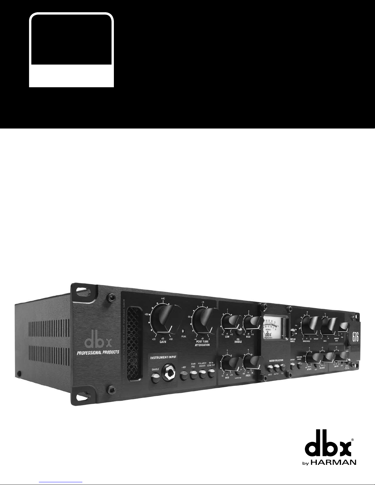
The dbx® 676 is a single-channel tube microphone preamplifier and channel strip processor with 3-band semi-parametric
EQ, compressor, and PeakPlus™ limiter. When used at the front of a digital audio workstation, tracks will take on more analog
warmth and sheen when compared to preamps built into standard audio recording interfaces.
The 676 preamp is a Class A, high-voltage (250V) vacuum tube design that can accommodate microphones or direct
instrument connections thanks to the front-panel Hi-Z instrument input. Use the PRE TUBE GAIN control to dial in just the
right amount of tube drive, then adjust the POST TUBE ATTENUATION control to set your gain back to unity. Keep the PRE
TUBE GAIN low and raise the POST TUBE ATTENUATION for an open, clean sound. Or, turn the PRE TUBE GAIN up and
lower the POST TUBE ATTENUATION for a tone that’s rich in harmonics and analog warmth. The 676 provides up to 60 dB
of low-noise gain, a 20 dB pad, +48 volt phantom power, and polarity inversion, making it well suited for a wide variety of
recording and live sound applications. Use the insert jack to patch in your favorite outboard compressor, EQ, or any other signal
processor post the preamp.
If you can’t quite achieve the tone you’re after with mic selection and placement alone, use the built-in semi-parametric EQ
to fine-tune the tone of the source. Engage the 80 Hz low cut filter to help keep the mix clean and maximize headroom by
eliminating subsonic plosives, hum, and microphone vibration noise.
The 676’s VCA compressor design was taken from the revered dbx 162SL and delivers smooth, low-distortion compression
characteristics, as well as very fast attack/release capabilities for shaping drum transients. Sources can be compressed gently
by engaging the OVEREASY switch (soft-knee mode) or aggressively by disengaging the OVEREASY switch (hard-knee
mode). Use the compressor to beef up instruments and voices, smooth out level fluctuations, and make your tracks more
‘mix-ready’. Compression attack and release times can be set manually or be program-dependent by engaging the AUTO
switch. Use the compressor’s sidechain jack to insert an outboard EQ for frequency-weighted compression, such as de-essing,
or for other creative sidechaining applications. The PeakPlus limiter can be used for level-critical applications, where you want
to keep the output level under control no matter how loud the source gets.
PREAMP and COMPRESSOR / LIMITER outputs are provided for parallel compression applications or for recording an
uncompressed backup, so there’s no need to worry about over-compressing a recorded track. An option slot can be fitted with
the digital output option card for high-quality onboard A/D conversion and direct connection to an AES or S/PDIF input on a
digital mixer or recording interface.
Whether you’re working in the studio or on the stage, the 676 adds harmonically-rich, warm analog tones to your sound
sources, at a fraction of the cost of other comparable products in its class.
Thanks for choosing dbx.
2

676
TUBE MIC
CHANNEL STRIP
Features
• Discrete, Class A, High-Voltage Tube Microphone Preamplifier
• 60 dB of Preamplifier Gain
• +48V Phantom Power
• 20 dB Pad
• Polarity Invert Switch
• 80 Hz Low Cut Switch
• Pre-Tube Gain & Post-Tube Attenuation Controls for Varying the Amount of Tube Drive
• 3-Band Semi-Parametric EQ with Sweepable Mid Frequency
• Built-In 162SL-Style Compressor
• dbx PeakPlus™ Limiter
• LED Backlit VU Meter with Selectable Meter Source
• Front-Panel Hi-Z Instrument Input
• 1/4˝ Preamp Insert Jack
• 1/4˝ Compressor Sidechain Jack
• Electronically Balanced XLR & TRS Preamp & Compressor / Limiter Outputs
• Slot for Optional AES / S/PDIF Digital Output Card
3
676
TUBE MIC
CHANNEL STRIP
Installation
Installation Recommendations
FOR RACK MOUNT USE ONLY. Install the 676 in a standard 19” rack with the provided rack screws. The 676 should not
be mounted above or below anything that generates excessive heat. Ambient temperatures should not exceed 95ºF (35ºC)
when equipment is in use.
Making Connections
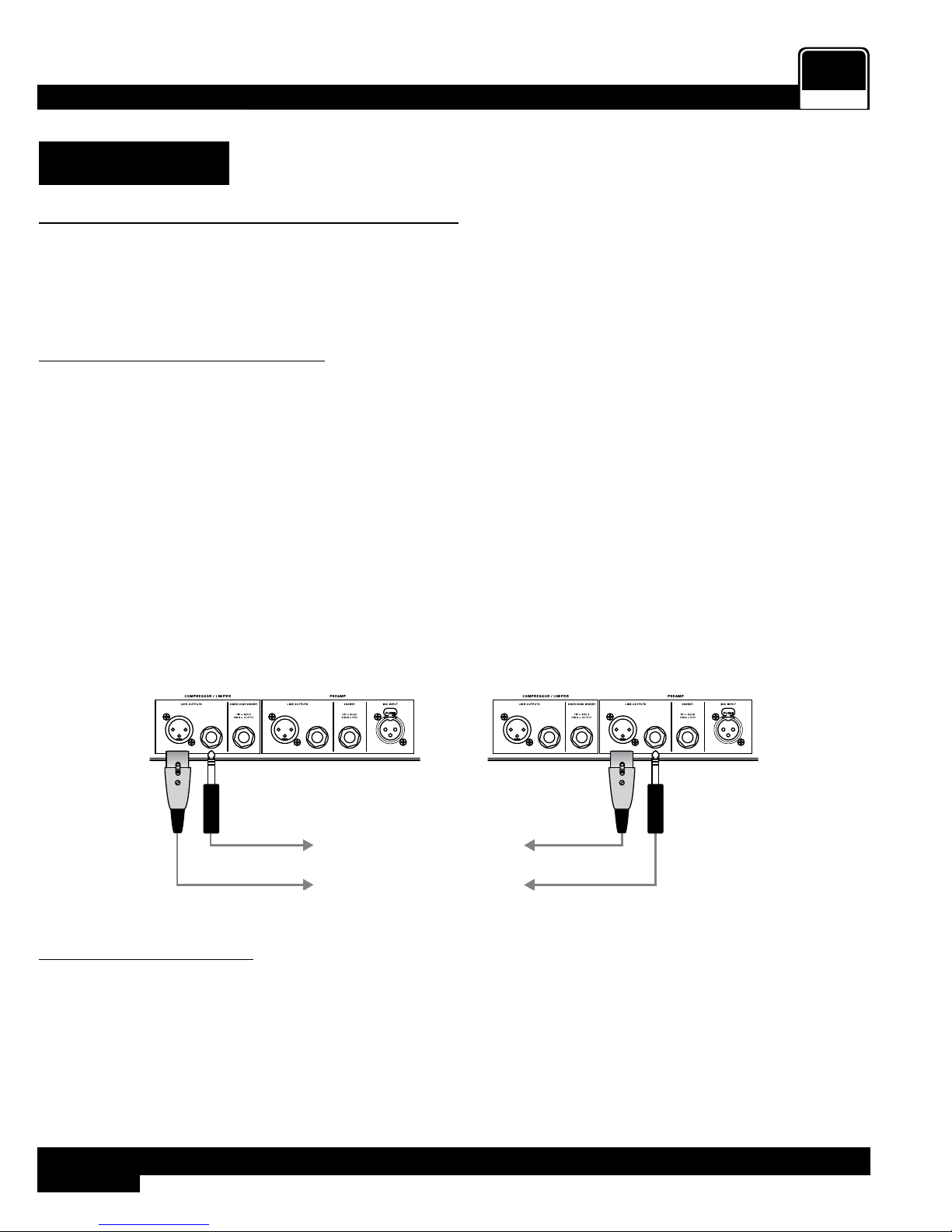
The 676 has balanced line outputs that can be connected to any balanced or unbalanced line-level device. To connect the 676
to your system:
1� Ensure the power is turned off on all interconnecting equipment and the 676 before making audio connections.
2� See ‘Application Guide’ on page 19 for application system diagrams and notes which can be used for reference
when connecting the 676 to your system.
3� Make audio connections via the XLR or 1/4˝ TRS connectors according to application needs (see ‘Audio Cable
Diagrams’ on page 25 for additional information on cable wiring). Either the XLR or 1/4˝ output connectors for
each output (i.e., PREAMP or COMPRESSOR / LIMITER output) can be used for balanced or unbalanced connections.
Connecting to both XLR and 1/4˝ outputs simultaneously (as shown in the below diagram) is perfectly acceptable as long
as the combined parallel load is 5kΩ or greater. This is typically not a problem since most modern-day audio devices have
been designed with high-impedance line inputs. If desired, parallel resistance calculators can be found online and used
to verify if the parallel load meets this criteria. Simply enter the input impedance for the two receiving devices into the
calculator to calculate the combined parallel load. Note that connecting both XLR and 1/4˝ outputs to an unbalanced and
balanced input simultaneously will cause the balanced line to become unbalanced.
or
To Device 1 Input
To Device 2 Input
Combined Load
5kΩ or Greater
Combined Load
5kΩ or Greater
To Device 1 Input
To Device 2 Input
Applying Power
1� Ensure your monitoring system is turned down before applying power to the 676.
2� Connect the power cord to the AC power inlet on the 676’s back panel and route the AC power cord to a convenient
power outlet away from audio lines.
3� Turn the 676 power switch to the on position.
4

676
TUBE MIC
CHANNEL STRIP
Quick Start
Follow these steps to get up and running fast:
1� Turn the POST ATTENUATION control all the way down.
2� Engage the INSTRUMENT INPUT button if connecting a bass or guitar to the INSTRUMENT INPUT jack on the front
panel. If connecting to the MIC INPUT jack on the rear panel, disengage the INSTRUMENT INPUT button.
3� Engage the +48V button if using a condenser microphone which requires it, otherwise, disengage the button.
4� Set the remaining preamp buttons for the application (i.e., 20dB PAD, POLARITY INVERSION, and 80 HZ LOW CUT), see
‘The Preamp Section’ on page 8 for further information on these buttons.
5� Set the GAIN and POST TUBE ATTENUATION knobs for the desired amount of tube drive and output level. For a cleaner
tone, use lower GAIN settings and higher POST ATTENUATION settings. For a tone with more harmonics and warmth,
use higher GAIN settings with a lower POST ATTENUATION setting.
6� Once microphone selection and position have been decided, enable the EQ with the EQ ENABLE button then adjust the
EQ settings to taste if any further tone shaping is required. If no EQ is required, leave the EQ ENABLE button in the off
position. See ‘The EQ Section’ on page 10 for further information on using the EQ.
7� Compression and limiting can be used to smooth-out overly dynamic source signals. If you wish to use compression and/
or limiting, you must be connected to the COMPRESSOR / LIMITER output. You can then enable the compressor/limiter
with the COMP/LIM ENABLE button and adjust the compressor/limiter settings to taste. For more information on using
the compressor/limiter, see ‘The Compressor & Limiter Section’ on page 12. For information on using both the
PREAMP and COMPRESSOR / LIMITER outputs, see ‘Parallel Compression’ on page 18.
5

The User Interface & Connectors
Front Panel
676
TUBE MIC
CHANNEL STRIP
CLASS “A” VACUUM TU BE WITH HIG H VOLTAG E GAI N
+40
+25 +50
dB
+55
∞
-
GAIN
INSTRUMENT INPUT
ENABLE
-30 -5
PEAK
-
∞
POST TU BE
ATTEN UATION
20dB
PAD+48V
POLARITY
INVER T
21 4 5
-15
dB
LOW CUT
0
dB
-15 +15
LOW
0
0
80 Hz
dB
-15 +15
MID
-15 +15
EQ
ENAB LE
200 2k
100 8k
NARRO W
HIG H
FREQ
0
dB
1k
Hz
3
METE R SE LECTI ON
INPU T OUTPUT G.R.
6
COMP/ LIM
ENAB LE
CONTOU R
-20
+
-30 +10
0
–
-400+20
THR ESHOLD
200 10
SIDE CHAI N
ENABL E
-10
dB
OVERE ASY
80
dB/msec
1
400
ATTACK
2:1
1.5:1 3:1
1.2:1 8:1
1:1 ∞:1
RATIO
400
1.5k 70
dB/sec
4k 10
RELEA SE
AUTO
0
-10 +10
dB
-20 +20
MAKE UP
GAIN
+10
+2 +18
dBu
-4
OFF
LIM ITER
|
PEAK
POWER
DIGI TAL
OUTPUT
LIMIT
RED: 96kHz
GREEN: 48kHz
YELLOW: 44.1 kHz
7 8
1. Preamp
This is the preamp section, see ‘The Preamp Section’ on page 8 for further information.
2. EQ
This is the EQ section, see ‘The EQ Section’ on page 10 for further information.
3. Meter
This LED backlit VU meter displays input signal level, output signal level, or the amount of gain reduction applied by the
compressor and/or limiter.
4. Compressor
This is the compressor section, see ‘The Compressor & Limiter Section’ on page 12 for further information.
5. Power Switch
This switch turns the power to the 676 on and off.
6. Meter Select Buttons [INPUT, OUTPUT, G.R.]
These buttons select what will be displayed in the VU meter, the selections are: INPUT (input level), OUTPUT (output
level), and G.R. (gain reduction applied by compression/limiting).
7. Limiter
This is the limiter section, see ‘The Compressor & Limiter Section’ on page 12 for further information.
8. Sample Rate Select Button [96 kHz, 48 kHz, 44.1 kHz]
This button selects the desired sample rate frequency for the digital output signal when the Digital Option Card is
installed. Note that this button will serve no function if the Digital Option Card is not installed.
6

676
1
3
TUBE MIC
CHANNEL STRIP
Rear Panel
2
4 5 7 86
1. Power Connector
Connect the included IEC power cord to this connector and the other end to an available AC outlet.
2. Fuse Drawer
This drawer houses the main power fuse as well as a replacement fuse, see ‘Replacing The Fuse’ on page 27
for further information.
3. Option Card Slot
This option card slot can be fitted with the 676 Digital Option Card (sold separately) which adds AES and S/PDIF
digital outputs. The Digital Option Card is equipped with high-quality A/D converters and our proprietary dbx Type IV™
conversion system to prevent the A/D converters from accidental clipping.
4. Compressor Line Output Connectors
This output carries the signal post-compressor/limiter. Both 1/4” and XLR balanced COMPRESSOR / LIMITER outputs
are provided. The COMPRESSOR / LIMITER output can be used by itself or along with the Preamp output for parallel
compression applications, see ‘Parallel Compression’ on page 18 for additional information.
5. Compressor Sidechain Insert Connector
Connect an insert cable to this unbalanced connector to patch in another device for processing the signal feeding
the compressor’s detector circuit. For example, an external EQ could be connected and used for frequency-weighted
compression, such as de-essing. See ‘Sidechain Application’ on page 21 for more information on using this
connector.
6. Preamp Line Output Connectors
This output carries the signal post EQ and pre compressor/limiter. It provides a slightly more minimalistic signal path
than the COMPRESSOR / LIMITER output. Both 1/4” and XLR balanced Preamp outputs are provided. The Preamp
output can be used by itself or along with the COMPRESSOR / LIMITER output for parallel compression applications,
see ‘Parallel Compression’ on page 18 for additional information.
7. Preamp Insert Connector
Connect an external signal processor to this unbalanced connector to process the signal just after the preamp section
and before the EQ.
8. Mic Input Connector
Connect a microphone or stage D.I. box to this balanced XLR input connector.
7
The Preamp Section
987654
1 2 3
676
TUBE MIC
CHANNEL STRIP
-30 -5
PEAK
-
∞
POST TU BE
ATTEN UATION
20dB
PAD+48V
POLARITY
INVER T
-15
dB
LOW CUT
0
dB
-15 +15
LOW
0
0
80 Hz
dB
-15 +15
MID
-15 +15
EQ
ENAB LE
200 2k
100 8k
NARRO W
HIG H
FREQ
0
dB
1k
METE R SE LECTI ON
Hz
INPU T OUTPUT G.R.
COMP/ LIM
ENAB LE
CONTOU R
-20
+
-30 +10
0
–
-400+20
THR ESHOLD
200 10
SIDE CHAI N
ENABL E
-10
dB
OVERE ASY
80
dB/msec
1
400
ATTACK
2:1
1.5:1 3:1
1.2:1 8:1
1:1 ∞:1
RATIO
400
1.5k 70
dB/sec
4k 10
RELEA SE
AUTO
0
-10 +10
dB
-20 +20
MAKE UP
GAIN
+10
+2 +18
dBu
-4
OFF
LIM ITER
|
PEAK
POWER
DIGI TAL
OUTPUT
LIMIT
RED: 96kHz
GREEN: 48kHz
YELLOW: 44.1 kHz
CLASS “A” VACUUM TU BE WITH HIG H VOLTAG E GAI N
+40
+25 +50
dB
+55
∞
-
GAIN
INSTRUMENT INPUT
ENABLE
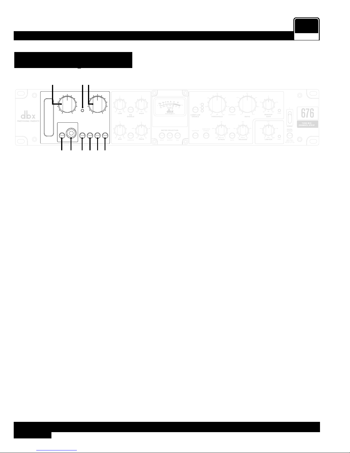
1. Gain Control
This control adjusts the amount of input gain applied to the preamp and how hard the tubes will be driven. Use lower
values to achieve a cleaner, more transparent sound. Use higher values for tones with more analog warmth, harmonics,
and sheen.
2. Peak LED
This LED lights when the input circuit is driven into clipping. Turn down the POST TUBE ATTENUATION control if this
LED begins to light.
3. Post Tube Attenuation Control
This control adjusts the amount of attenuation applied post the tube preamplifier and is meant to be used in conjunction
with the GAIN control. For cleaner tones, leave this control fully clockwise and raise the GAIN control until the desired
level is achieved. For richer tones, lower this control and raise the GAIN control.
4. Instrument Input Enable Button
This button enables/disables the INSTRUMENT INPUT. When enabled, the signal connected to the INSTRUMENT
INPUT will be passed through the 676. When disabled, the 676 will pass the audio from the MIC INPUT connector
located on the back panel.
5. Instrument Input Connector
Connect an electric guitar or bass directly to this unbalanced, Hi-Z input.
6. +48V Button
This button enables/disables +48 volt phantom power. Enable it for condenser microphones which require an external
power source. Leave this button disabled when connecting a dynamic or ribbon microphone, or a condenser microphone
which is powered internally or using its own dedicated power supply.
7. 20dB Pad Button
Engage this button to attenuate the input signal by 20 dB. Use it to prevent the MIC INPUT from being overdriven by
loud source signals or high-output microphones.
8. Polarity Invert Button
When enabled, this button inverts the polarity of the MIC INPUT signal. Use it with multi-miked applications where
polarity inversion is required to match the polarity of the MIC INPUT signal with another miked signal – for example,
when using top and bottom mics on a snare drum.
8
 Loading...