


A.E.B. INDUSTRIALE s.r.l.
Via Brodolini, 8 - 40056 Crespellano (Bo) - ITALIA
Tel. + 39 051 969870 - Fax. + 39 051 969725 Internet: www.dbtechnologies.com
E-mail: info@dbtechnologies-aeb.com
Digital Vertical Array
T
MANUALE d’USO - Sezione 1
USER MANUAL - Section 1
BEDIENUNGSANLEITUNG - Abschnitt 1
CARACTERISTIQUES TECHNIQUES - Section 1
COD. 420120184 Rev 3.0 |
Made in Italy |
Manuale d’uso ItalianoItaliano
1
DESCRIZIONE
Il diffusore DVA T12 è equipaggiato con tre amplificatori in classe D della serie DIGIPRO® G2, ad alta efficienza, che permettono di ottenere elevate potenze di uscita con pesi ed ingombri ridotti. Grazie alla sua bassa potenza dissipata, il raffreddamento del modulo amplificatore avviene in modo statico, evitando l’uso della ventola.
Il circuito di alimentazione dell’amplificatore DIGIPRO® G2 è stato progettato per lavorare in modalità full-range; grazie alla tecnologia SMPS (Switched-Mode Power Supplies) con PFC (Power Factor Correction) viene garantito il funzionamento a tensioni di alimentazioni da 100V a 240V, garantendo le stesse prestazioni acustiche anche con linee di alimentazione fluttuanti e non stabilizzate.
Il modulo amplificatore è in grado di erogare 710W (RMS) per la sezione dei bassi, 350W (RMS) per la sezione dei medi e 350W (RMS) per la sezione degli alti.
La sezione dei bassi pilota un woofer 12" al neodimio (voice coil 3") in configurazione band-pass alloggiato inclinato all’inteno del box. Tale configurazione garantisce un elevato SPL ed il raggiungimento di frequenze fino a 60Hz.
La sezione dei medi pilota due midrange, da 6,5" al neodimio (voice coil 2"), alloggiati nella propria camera acustica e caricati a tromba con rifasatore. I phase plug montati davanti ai coni evitano le sovrapposizioni di fase verticali creando di fatto un array locale a 6 slot di uscita, che ne aumenta la direttività. Il disegno della tromba è stato appositamente progettato per il corretto accoppiamento con i moduli DVAT4.
La sezione degli alti pilota tre driver da 1" al neodimio (voice coil 1.5") montati verticalmente su un supporto di alluminio e distaziati per ottimizzare la copertura verticale. Il disegno della tromba è stato appositamente progettato per il corretto accoppiamento con i moduli DVAT4.
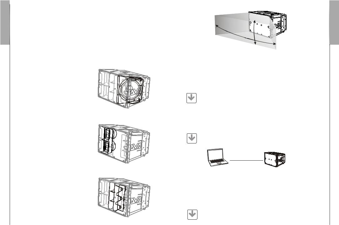
Una progettazione mirata ha permesso di raggiungere una costante e precisa copertura di 100° in senso orizzontate e 10° in senso verticale per ogni diffusore.
100°
10°
DVA Network
Il DVA T12 è equipaggiato con interfaccia di rete proprietaria, denominata RDNET tramite la quale è possibile interfacciarsi al computer attraverso una periferica (RDNET control).
A questo scopo è stato sviluppato il protocollo proprietario di comunicazione RDnet con il quale è possibile ricevere e inviare i dati; questo collegamento permette di monitorare in tempo reale i parametri del diffusore come livello del segnale, stato del limiter, etc...
E’ possibile selezionare diversi valori di crossover, delay, volume ed aggiungere equalizzazioni, tramite l’apposito plug-in.
|
Si raccomanda di scaricare gratuitamente il software DVA Network direttamente |
|
dal sito dB Technologies (www.dbtechnologies.com) nella sezione dedicata |
DOWNLOAD |
«Software & Controller» |
|
DVA USB Manager
Il firmware del modulo amplificatore può essere aggiornato attraverso la porta USB.
Per rendere possibile e facile questo aggiornamento è stato sviluppato un software dedicato.
|
Si raccomanda di scaricare gratuitamente il software DVA USB Manager |
|
direttamente dal sito dB Technologies (www.dbtechnologies.com) nella sezione |
DOWNLOAD |
dedicata «Software & Controller» |
|
|
|
PC |
DVA Composer - Simulazione acustica di sistemi serie DVA
DVA Composer è un software di puntamento e simulazione acustica per tutti i modelli Line
Array della serie DVA e relativi Subwoofers.
Tale software permette di gestire un sistema stereo composto da line array e subs, simulando separatamente la risposta acustica di entrambi
Vengono inoltre fornite all'utente una serie di informazioni quali allineamento in fase tra i sistemi sospesi e i relativi subwoofer a terra e vengono suggeriti angoli ottimali tra i moduli line array e relativi preset di equalizzazione, al fine di ottimizzare le performance del sistema anche per utenti non esperti.
|
Si raccomanda di scaricare gratuitamente il software DVA_Composer |
|
direttamente dal sito dB Technologies (www.dbtechnologies.com) nella |
DOWNLOAD |
sezione dedicata «Software & Controller» |
Manuale d’uso ItalianoItaliano
2
ItalianoItaliano
3
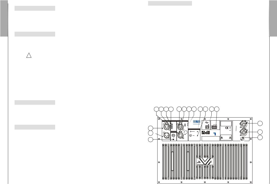
COMANDI E FUNZIONI
Sezione “Balanced Audio”
1)CONNETTORE DI INGRESSO " INPUT”
Connettore XLR ingresso bilanciato a livello linea .
2)CONNETTORE DI USCITA "LINK”
Il connettore “XLR” connesso in parallelo con l’ingresso (1) può essere utilizzato per inviare il segnale audio in ingresso ad un altro diffusore amplificato.
Sezione “Status”
3)INDICATORE LUMINOSO “LIMITER”
Questo indicatore s’illumina di colore rosso per indicare l'intervento del circuito limitatore interno, il quale evita la distorsione dell'amplificatore e protegge gli altoparlanti contro sovraccarichi.
! |
Evitare di utilizzare il sistema per lunghi periodi di tempo con l’indicatore |
luminoso acceso fisso o lampeggiante. |
4) INDICATORE LUMINOSO “SIGNAL”
Questo indicatore si illumina di colore verde per indicare la presenza di un segnale in ingresso di un livello superiore ai -20dBu.
5) INDICATORE LUMINOSO “MUTE/PROT”
Questo indicatore di colore giallo indica lo stato dell’amplificatore. Nel normale funzionamento il led è spento; nel caso in cui lampeggi o sia sempre acceso fare riferimento alla tabella della diagnostica per la verifica dello stato dell’amplificatore.
6) INDICATORE LUMINOSO “READY”
Questo indicatore s'illumina di colore verde per indicare che la tensione di alimentazione di rete è corretta. Nel normale funzionamento il led è acceso; nel caso in cui lampeggi o sia spento fare riferimento alla tabella della diagnostica per la verifica dello stato dell’amplificatore.
Sezione “Input control”
7)CONTROLLO SENSIBILITA’ INGRESSO “INPUT SENS”
Questo controllo regola la sensibilità del segnale in ingresso all’amplificatore.
Tale controllo non influisce sul livello dell’uscita “LINK” (2)
Sezione “RDNET”
8)CONNETTORE DI INGRESSO "DATA INPUT”
Connettore RJ45 ’ingresso dati .
9)CONNETTORE DI USCITA "DATA LINK”
Connettore RJ45 ’uscita dati per il collegamento seriale in cascata.
10)INDICATORE LUMINOSO “LINK”
Questo indicatore di colore Verde si accende solo quando l’amplificatore ha riconosciuto ed è connesso con unità principale RDNET tramite computer.
11)INDICATORE LUMINOSO “ACTIVE”
Questo indicatore di colore Giallo lampeggia quanto è attiva una trasmissione dati tra
RDNET e modulo amplificatore.
Sezione “DSP configuration”
12)INDICATORE LUMINOSO “Remote Preset Active”
Questo indicatore di colore Giallo indica l’esclusione del comando Volume e del commutatore rotativo “DSP Preset” (13) quando l’amplificatore è controllato in remoto da un computer tramite RDNET.
L’indicatore lampeggia lentamente se il selettore rotativo è in posizione 9 ed è stata memorizzata una equalizzazione utente precedentemente salvata.
13)SELETTORE ROTATIVO a 10 posizioni “DSP Preset”
Questo commutatore rotativo a 10 posizioni permette di selezionare le nove curve di equalizzazione predisposte (selettore da 0-8) o di richiamare l’equalizzazione precedentemente salvata dall’utente tramite RDNET (selettore 9).
Nel caso in cui non venga utilizzata questa opzione la curva 9 sarà uguale alla curva 0 Consultare la tabella per la corrispondenza delle curva di equalizzazione.
14)Connettore “Service Data USB”
Tramite questo connettore USB è possibile aggiornare il firmware del modulo amplificatore DVAT12 tramite un computer ed un programma dedicato.
15)Connettore “Optional device”
Connettore a 8 poli è utilizzato per collegamenti opzionali futuri.
16)PRESA DI ALIMENTAZIONE “MAINS INPUT”
Consente la connessione del cavo di alimentazione.
Il connettore utilizzato per il collegamento alla rete è un POWER CON® (blu)
17)PRESA DI ALIMENTAZIONE RILANCIO “MAINS OUTPUT LINK”
Consente di rilanciare l’alimentazione di rete. L’uscita è connessa in parallelo con l’ingresso (16) e può essere utilizzata per alimentare un altro diffusore amplificato.
Il connettore utilizzato è un POWER CON® (grigio).
18)PORTA FUSIBILE “MAINS FUSE”
Alloggio per fusibile di rete.
6 |
5 |
4 |
3 |
8 |
9 |
10 11 |
12 13 |
14 15 |
1
2 
7
Balanced Audio |
Status |
RDNET |
dB |
|
|
Optional |
SERIAL N. |
||||
PUSH |
|
PUSH |
TECHNOLOGIES |
|
Device |
|
|||||
|
Limiter |
Link |
|
|
|
|
|
||||
|
Signal |
Active |
|
|
|
|
|
Service |
|
|
|
|
Mute/Prot |
|
|
|
|
|
|
Data |
|
|
|
|
Ready |
Data |
|
|
DSP Configuration |
USB |
|
|
|
||
Input |
|
Input |
|
|
|
T |
|
Made in Italy |
|||
|
|
|
|
|
|
|
|
||||
|
|
|
|
|
|
|
Remote |
|
|
||
|
Input Control |
PUSH |
|
|
|
|
|
|
|
||
|
|
|
|
|
|
Preset |
|
|
|
||
|
+4dB |
|
|
9 |
0 |
|
Active |
|
|
|
|
|
|
8 |
1 |
2 |
|
Digital Vertical Array |
|
|
|||
|
|
|
|
|
DSP |
|
“CAUTION” |
||||
|
|
|
7 |
6 |
4 |
3 |
|
2 RISK OF ELECTRICAL SHOCK |
|||
|
0dB |
Data |
Preset |
|
|
DO NOT OPEN |
|||||
Link |
|
|
5 |
|
|
|
|
|
|
||
Input Sens |
Link |
|
|
|
|
|
|
|
|
“AVIS” |
|
|
|
|
|
|
|
|
|
|
|
|
RISQUE DE CHOCH ELECTRIQUE |
|
|
|
|
|
|
|
|
|
|
|
NE PAS OUVRIR |
FULL RANGE |
16 |
MAINS INPUT |
|
100-240V~ 50-60Hz |
|
8-4Amax |
|
ACTIVE P.F.C. |
|
MAINS LINK |
17 |
220-240V~ |
|
3680Wmax (16A max) |
|
100-120V~ (12A max) |
|
1320Wmax |
18 |
MAINS FUSE |
|
220-240V~ (T6,3A L 250V~) |
|
100-120V~ (T10A L 250V~) |
|
(REPLACE FUSE WITH SAME RATINGS) |
Manuale d’uso ItalianoItaliano
4

Manuale d’uso ItalianoItaliano
5
CARATTERISTICHE E PROTEZIONI
Griglie frontali
Visto l’utilizzo professionale di questi diffusori, i componenti sono protetti frontalmente da una lamiera forata con spessore 1,2mm e foam interno.
Raffreddamento
Il controllo termico è gestito dal microprocessore centrale (main) che interagendo con i microprocessori locali (amplificatori e alimentatore) comunica i dati al DSP per le eventuali correzioni.
In caso di surriscaldamento eccessivo del modulo amplificatore, il volume viene ridotto gradualmente a step di 0,1dB fino alla stabilizzazione termica del modulo.
Il volume viene ripristinato automaticamente al raggiungimento delle normali temperatura di esercizio.
Accensione
La regolare accensione del diffusore è garantita da una procedura di inizializzazione durante la quale il modulo è alimentato dall’alimentatore ausiliare.
Quando tutte le periferiche dell’amplificatore vengono correttamente rilevate viene attivato l’alimentatore principale.
La tecnologia (RANDOM POWER ON ) introduce un ritardo casuale e differenziato per ogni modulo prima della accensione della PSU (Power Supply Unit) principale.
Questo evita che gli spunti di corrente in accensione dei vari moduli si sommino sovraccaricando la linea di alimentazione AC.
Al termine della procedura di avvio, sul modulo amplificatore solo il LED verde “READY” rimane acceso fisso.
Indicazioni di guasto e protezioni
Il microprocessore centrale è in grado di segnalare diversi tipi di guasti tramite diversi lampeggi dei LED “READY”, “MUTE/PROT” e “LIMIT” come riportato nella tabella della diagnostica
I tre tipi di guasto possibili sono:
1)ATTENZIONE: viene rilevato una errore o un malfunzionamento autoripristinate non grave e le prestazioni del diffusore non vengono limitate
2)LIMITAZIONE: viene rilevato un errore e vengono limitate le prestazioni del diffusore . Il livello sonoro viene ridotto oppure vengono disabilitati uno o più amplificatori.
Questo stato influisce parzialmente sul funzionamento corretto del diffusore. Se il problema persiste alle successive accensioni del modulo è nessario contattare il centro assistenza per risolvere il problema.
3)GUASTO: viene rilevato un malfunzionamento grave. Il diffusore viene posto nello stato di “mute”.
Nel caso di malfunzionamento, prima di contattare il centro di assistenza, provare a spegnere e riaccendere il modulo per verificare la continuità del problema.
Collegamento alla alimentazione di rete
Il collegamento alla rete avviene tramite un connettore modello Neutrik POWER CON® (blu) che permette di avere una facile e rapida connessione al diffusore oltre che a un ottimo sistema di bloccaggio.
Lo stesso connettore serve da interruttore per accendere e spegnare il diffusore.
L’apparecchio dovrà essere collegato ad una rete di alimentazione che possa erogare la massima potenza richiesta.
Rilancio alimentazione di rete
Sul retro del diffusore è presente un connettore Neutrik POWER CON® (grigio) per il rilancio di alimentazione di rete.
Questa presa ha lo scopo di rilanciare l’alimentazione ad un altro diffusore riducendo i collegamenti diretti alla rete. Gli assorbimenti massimi degli amplificatori sono riportati sul pannello dell’amplificatore.
Il numero massimo dei diffusori collegati insieme varia sia per gli assorbimenti massimi dei diffusori e sia dalla corrente massima della prima presa di alimentazione.
TABELLA DELLA DIAGNOSTICA |
STATO LED LED LED LED FUNZIONI MODULO |
DEL MODULO «READY» «MUTE/PROT» «SIGNAL» «LIMIT» |
Accensione Spento Acceso per 5 sec. Spento Spento Audio in MUTE |
Inizializzazione del modulo amplificatore |
Uso normale Acceso fisso Spento Funzionamento normale Funzionamento normale Audio ATTIVO |
Inizializzazione del modulo completata e corretta |
Anomalia parziale Acceso fisso Lampeggio ciclico Funzionamento normale Funzionamento normale Audio ATTIVO |
(3 o più lampeggi veloci) Il modulo ha rilevato una anomalia parziale e rimane |
attivo con funzionalità limitate |
Anomalia totale Spento Acceso fisso Spento Lampeggio ciclico Audio in MUTE |
Il modulo ha rilevato una anomalia grave e rimane in |
protezione |
Gestione temperatura amplificatore: |
Prima soglia Acceso fisso Lampeggio ciclico Funzionamento normale Funzionamento normale Audio ATTIVO |
termica (1 lampeggio lento) Il modulo amplificatore comincia una graduale |
diminuzione del volume a step di 0.1dBm per |
compensare l’ aumento della temperatura fino ad un |
massimo di riduzione di 3dBm. |
Seconda soglia Acceso fisso Lampeggio ciclico Funzionamento normale Funzionamento normale Audio ATTIVO |
termica (2 lampeggi veloci) Il modulo amplificatore riduce il volume di ulteriori 3dBm |
sempre a step graduali di 0.1dBm fino ad un massimo |
di riduzione di altri 3dBm, per una totale riduzione di |
6dBm rispetto al volume originale. |
N.B. Le temperature visualizzate sul plug-in del software RDnet si riferiscono alle temperature interne dei semiconduttori di potenza. |
Tali temperature visualizzate non sono le temperature delle parti accessibili dall’utente |
STATO LED LED LED FUNZIONI MODULO |
DEL MODULO «Remote Preset Active» «LINK» «ACTIVE» |
RDNET non attiva Spento Spento Spento Il modulo funziona normalmente |
Il volume (INPUT SENS) e il commutatore rotativo (DSP Preset) |
sono attivi |
RDNET collegata Acceso fisso Acceso fisso Lampeggio ciclico Il modulo amplificatore è controllato in remoto dall’RDNET |
(Attività dati) Il volume (INPUT SENS) e il commutatore rotativo (DSP Preset) |
sono bypassati |
Equlizzazione «USER EQ» Lampeggio ciclico Spento Spento Il modulo funziona normalmente |
(commutatore rotativo Si sta utilizzando l’equalizzazione salvata tramite RDNET |
«DSP Preset» in posizione 9) |
Manuale d’uso ItalianoItaliano
6
Manuale d’uso ItalianoItaliano
7
DATI TECNICI
Sistema |
Attivo 3-Amps |
Tipologia amplificatore |
Digitale - Classe D |
|
Tecnologia DIGIPRO G2 |
Potenza RMS |
1410W |
Alti (HF) RMS |
350W |
Medi (MF) RMS |
350W |
Bassi (LF) RMS |
710W |
Potenza musicale |
2820W |
Risposta in frequenza (-6dB) |
60-19.000Hz |
Crossover MF-HF (Medi-Alti) |
1900Hz |
|
24dB/Oct |
Crossover LF-MF (Bassi -Medi) |
420Hz |
|
24dB/Oct |
Pressione sonora (SPL) |
136dB max |
Componenti |
1 woofer 12" - VC 3" - Neodimio |
|
2 midrange 6,5" - VC 2" - Neodimio |
|
3 compression driver 1" - VC 1.5" - Neodimio |
Sensibilità ingresso nominale |
0dBu |
Impedenza ingresso |
|
Bilanciato |
20Kohm |
Sbilanciato |
10Kohm |
Alimentazione |
Full-range con PFC e SMPS |
|
100-240V~ 50-60Hz |
Corrente di accensione |
14,9A |
Dimensioni (LxHxP) |
580x386x430mm |
Peso |
29,9Kg |
PROCESSORE DSP |
|
DSP |
Analog Device 56 bits |
Conversione audio |
24 bit / 96kHz S/N=116dB |
Controllo volume |
Digitale |
Equalizzazione |
9 preset EQU |
MECCANICA |
|
Materiale box |
Polipropilene (PP) |
Rinforzi interni box |
Alluminio |
Materiale staffe appendibilità |
Acciaio |
Angolazioni staffe |
0° - 1,5° - 3° - 4,5° - 6° - 8° - 10° |
Forma del diffusore |
Trapeziodale - angolazione 10° |
Maniglia |
1 x lato |
Rete frontale |
Lamiera forata 1.2mm con foam interno. |
CLASSIFICAZIONE EMI
In accordo alle normative EN 55103, l'apparato è progettato e idoneo all'utilizzo in ambienti Elettromagnetici E3 o inferiori (E2, E1).
DESCRIPTION
The DVAT12 is equipped with three class D amplifiers of DIGIPRO® G2 series, high efficiency, which delivers high output power in a compact size and low weight. Thanks to its high efficiency the cooling of the amplifier module is obtained statically, thus avoiding the use of a fan.
The power supply circuits of the DIGIPRO® G2 amplifier has been conceived to work in fullrange mode; thanks to the SMPS (Switched-Mode Power Supplies) technology with PFC (Power Factor Correction) the operation with supply voltages between 100 Vac and 240Vac is guaranteed by ensuring the same sound performances even with floating and non-stabilized power supply systems.
The amplifier module is able to deliver 710W (RMS) for the bass section, 350W (RMS) for the mid-section and 350W (RMS) for the treble section.
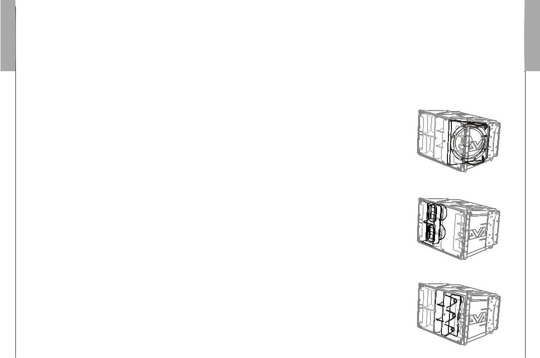
The bass section controls a 12" neodymium woofer (3" voice coil) in a band-pass configuration enclosed inclined inside the box. This configuration guarantees a high SPL and the obtainment of frequencies of up to 60Hz.
The mid-section controls two 6.5" neodymium midranges (2" voice coil), enclosed in their own acoustic chamber and horn loaded with a power factor corrector. The plug phases located in front of the cones prevent the vertical phases from overlapping, creating in fact a local array with 6 output slot that increases directivity. The horn design was specifically created to couple it correctly with the DVAT4 modules.
The treble section controls three 1" neodymium drivers (1.5" voice coil) positioned vertically on an aluminum support and spaced to optimize the vertical cover.
The horn design was specifically created to couple it correctly with the DVAT4 modules.
EnglishEnglish
user manual
8
EnglishEnglish
user manual
9
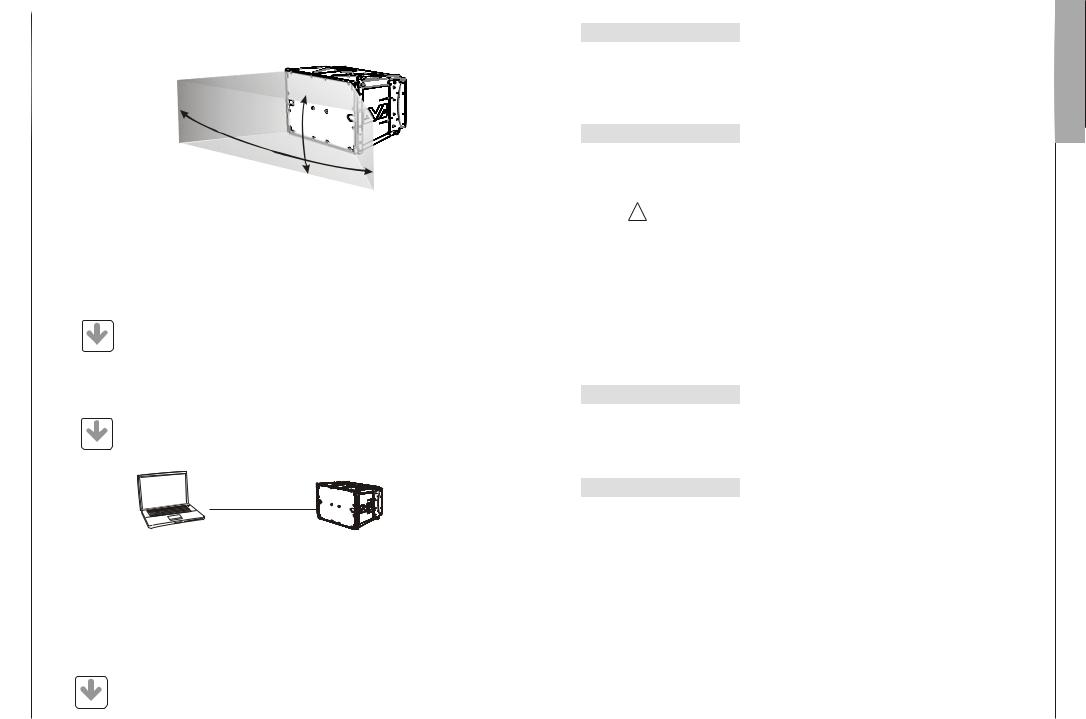
This specific design has made it possible to obtain a constant and precise 100° coverage in a horizontal direction and 10° coverage in a vertical director for each diffuser.
100°
10°
DVA Network
DVA T12 is equipped with proprietary network interface, called RDNET, for PC interface through a device (RDNET control).
For this purpose, a proprietary communication protocol has been developed for receiving and sending data; this connection permits real-time monitoring of the diffuser parameters, such as output power, amplifier temperature, limiter status, etc...
It is also possible to select various equalizations or create new ones, set the desired volume levels using the specific plug-in.
It is recommended to download DVA Network free software directly from dB
Technologies (www.dbtechnologies.com) in the special section «Software & DOWNLOAD Controller»
DVA USB Manager
The firmware of the amplifier module can be updated via the USB port.
To make this update possible and simple, a dedicated program has been developed.
|
It is recommended to download DVA USB Manager free software directly from |
|
dB Technologies (www.dbtechnologies.com) in the special section «Software & |
DOWNLOAD |
Controller» |
|
|
|
PC |
DVA Composer Acoustical Simulation and aiming for DVA Systems
DVA Composer is a 2D software for aiming and simulating acoustical response of all line arrays and Subwoofers from DVA Series.
The software allows you to set up a stereo system composed by tops and subs, and simulates separately the acoustical response of both
DVA Composer also gives to the user all the information about phase alignment between flown systems and ground stacked subwoofers, as well as it suggests an optimized aiming of the line arrays modules and their suggested EQ presets, in order to guarantee maximum performances even for non-expert customers.
It is recommended to download DVA_Composer free software directly from dB Technologies (www.dbtechnologies.com) in the special section «Software &
DOWNLOAD Controller»
CONTROLS AND FUNCTIONS
"Balanced Audio" section
1)" INPUT” INPUT CONNECTOR
Balanced input at line level. It is able to accept “XLR” sockets.
2)"LINK” OUTPUT CONNECTOR
The “XLR” connector connected in parallel with input (1) can be used to send the input audio signal to another amplified speaker.
"Status" section
3)“LIMITER” INDICATOR LIGHT
This indicator comes on red to indicate that the internal limiter circuit has tripped. This prevents amplifier distortion and protects the speakers against overloads.
Always avoid operating conditions where the system works for long periods of
!time with LED flashes or it is always ON
4)“SIGNAL” INDICATOR LIGHT
This indicator comes on green to indicate the presence of an input signal to a level higher than-20dBu.
5)“MUTE/PROT” INDICATOR LIGHT
This yellow indicator indicates amplifier status. In normal operating conditions, the LED is off; if it flashes or is always on, refer to the diagnostics table to check amplifier status.
6)“READY” INDICATOR LIGHT
This indicator comes on green to indicate that the main power voltage is correct. In normal operating conditions, the LED is on; if it flashes or is off, refer to the diagnostics table to check amplifier status.
"Input control " section
7)“INPUT SENS” INPUT SENSITIVITY CONTROL
This control regulates the sensitivity of the signal amplifier input.
This control does not affect the “BALANCED LINK/OUT” output level
"RDNET " section
8)INPUT CONNECTOR "DATA INPUT”
RJ45 connector 'data input.
9)OUTPUT CONNECTOR "DATA INPUT”
RJ45 connector 'data output for cascading connections.
10)“LINK” INDICATION LIGHT
This green indicator turns on only when the amplifier has recognized and is connected with the main RDNET unit via the computer.
11)“ACTIVE” INDICATOR LIGHT
This yellow indicator flashes when there is an active data transmission between RDNET and the amplifier module.
EnglishEnglish
user manual
10

EnglishEnglish
user manual
11
"DSP configuration" section
12) “Remote Preset Active” INDICATION LIGHT
This yellow indicator indicates the exclusion of the Volume control and the “DSP
Preset” rotary switch (13) when the amplifier is remotely controlled by a computer via RDNET.
The indicator flashes slowly if the rotary switch is set to 9 and a previously saved user equalization has been stored.
13) “DSP Preset” 10-position ROTARY SWITCH
This 10-position rotary switch makes it possible to select the nine preset equalization curves (selector 0-8) or to select the equalization previously saved by the user via RDNET (selector 9).
If this option is not used, curve 9 will be equal to curve 0
Refer to the table for the correspondence of the equalization curve.
14) “Service Data USB” Connector
Via this USB connector, it is possible to update the firmware of the DVA T12 amplifier module using the computer and a dedicated program.
15) “Optional device”Connector
This 8-pole connector is used for future optional connections.
16)"MAINS INPUT" POWER SOCKET
For connecting the power cable.
The connector used for mains connection is a POWER CON® (blue)
17)“MAINS OUTPUT LINK” RELAUNCH POWER SOCKET
For relaunching the mains power. The output is connected in parallel with input (16) and can be used to power another amplified speaker.
The connector uses a POWER CON® (grey)
18)"MAINS FUSE" FUSE CARRIER
Mains fuse housing.
6 |
5 |
4 |
3 |
8 |
9 |
10 11 |
12 13 |
14 15 |
1
2 
7
Balanced Audio |
Status |
RDNET |
dB |
|
|
Optional |
SERIAL N. |
||||
PUSH |
|
PUSH |
TECHNOLOGIES |
|
Device |
|
|||||
|
Limiter |
Link |
|
|
|
|
|
||||
|
Signal |
Active |
|
|
|
|
|
Service |
|
|
|
|
Mute/Prot |
|
|
|
|
|
|
Data |
|
|
|
|
Ready |
Data |
|
|
DSP Configuration |
USB |
|
|
|
||
Input |
|
Input |
|
|
|
T |
|
Made in Italy |
|||
|
|
|
|
|
|
|
|
||||
|
|
|
|
|
|
|
Remote |
|
|
||
|
Input Control |
PUSH |
|
|
|
|
|
|
|
||
|
|
|
|
|
|
Preset |
|
|
|
||
|
+4dB |
|
|
9 |
0 |
|
Active |
|
|
|
|
|
|
8 |
1 |
2 |
|
Digital Vertical Array |
|
|
|||
|
|
|
|
|
DSP |
|
“CAUTION” |
||||
|
|
|
7 |
6 |
4 |
3 |
|
2 RISK OF ELECTRICAL SHOCK |
|||
|
0dB |
Data |
Preset |
|
|
DO NOT OPEN |
|||||
Link |
|
|
5 |
|
|
|
|
|
|
||
Input Sens |
Link |
|
|
|
|
|
|
|
|
“AVIS” |
|
|
|
|
|
|
|
|
|
|
|
|
RISQUE DE CHOCH ELECTRIQUE |
|
|
|
|
|
|
|
|
|
|
|
NE PAS OUVRIR |
FULL RANGE |
16 |
MAINS INPUT |
|
100-240V~ 50-60Hz |
|
8-4Amax |
|
ACTIVE P.F.C. |
|
MAINS LINK |
17 |
220-240V~ |
|
3680Wmax (16A max) |
|
100-120V~ (12A max) |
|
1320Wmax |
18 |
MAINS FUSE |
|
220-240V~ (T6,3A L 250V~) |
|
100-120V~ (T10A L 250V~) |
|
(REPLACE FUSE WITH SAME RATINGS) |
CHARACTERISTICS AND PROTECTION
Front Grille
The speakers’s components in the box are protected by 1.2mm metal steel grille covered by foam on backside.
Cooling
Thermal control is managed by the main microprocessor that interacts with the local microprocessors (amplifiers and power supply) and communicates the data to the DSP for any corrections.
If the amplifier module heats up excessively, the volume is gradually reduced step wise to
0.1dB until the module is thermally stabilised.
The volume is automatically restored when the normal operating temperature is reached.
Power on
The diffusor is powered up normally by an initialization process during which the module is powered by the auxiliary power supply.
When all of the amplifier peripherals are correctly detected, the main power supply is activated.
The technology (RANDOM POWER ON ) introduces a random and differentiated delay for each module prior to the power on of the main PSU (Power Supply Unit).
This prevents the breakaway starting currents of the various modules from accumulating, overloading the AC power supply line.
At the end of the power on procedure, only the green “READY” LED will remain on fixed on the amplifier module.
Failure indications and safeties
The microprocessor is able to signal three different kinds of failure by flashing the “LIMTER” red LED on the amplifier panel before the lighting up of the “READY” green LED. The three types of failure are:
1)WARNING: a non severe error or auto-ripristinate malfunction is detected and the performance of the speaker is not limited
2)LIMITATION: an error is detected and diffuser performance is limited. The sound level is reduced or one or more amplifiers are disabled.
This state partially influences the correct functioning of the diffuser.
If the problem persists the next time the module is turned on, contact the support centre for assistance.
3)FAILURE: a severe malfunction is detected. The speaker switches to “mute”.
If the case of a malfunction, before contacting the support centre, try to turn the module off and on to check if the problem still exists.
Connecting to the mains supply
Each active speaker features its own power cable. Connection is done by a Neutrik POWER CON® (blue) model which permits easy and fast connection to the speaker as well as being an excellent locking system.
The same connector serves as a switch to turn ON and OFF the active loudspeaker by turning the connector to the left (OFF) or right (ON).
The active speaker must be connected to a power supply able to deliver the maximum required power.
Main power supply linking
On the rear of the speaker, a Neutrik POWER CON® connector (grey) offers linking the mains power supply.
This socket links the power supply to another speaker, thereby reducing the direct connections to the mains. Maximum amplifier input power is shown on the amplifier panel.
The maximum number of speakers connected together varies of max input power and of the maximum allowed current of the first power socket.
EnglishEnglish
user manual
12

EnglishEnglish
user manual
13
DIAGNOSTICS TABLE |
MODULE LED LED LED LED MODULE FUNCTIONS STATUS «READY» «MUTE/PROT» «SIGNAL» «LIMIT» |
Power ON OFF ON for 5 sec. OFF OFF Audio MUTED Initialization of the amplifier module |
Normal use ON OFF Normal operation Normal operation Audio ACTIVE Module initialization complete and correct |
Partial fault ON Cyclic flashing Normal operation Normal operation Audio ACTIVE (3 or more quick flashes) The module has detected a partial anomaly and remains active with limited functions |
Total fault OFF ON OFF Cyclic flashing Audio MUTED The module has detected a serious anomaly and is in protected mode |
Amplifier temperature management: First thermal ON Cyclic flashing Normal operation Normal operation Audio ACTIVE threshold (1 slow flashes) The amplifier module begins a gradual decrease of the volume in 0.1dBm steps to compensate 'temperature increase up to a maximum reduction of 3dBm. |
Second thermal ON Cyclic flashing Normal operation Normal operation Audio ACTIVE threshold (2 quick flashes) The amplifier module reduces the volume further 3dBm always in 0.1dBm steps up to a maximum reduction of 6dBm respect original volume. NB The temperatures shown on the plug-in RDnet software refer to the internal temperature of the power semiconductors. These temperatures are not displayed the temperatures of accessible parts user |
MODULE STATUS LED LED LED MODULE FUNCTIONS «Remote Preset Active» «LINK» «ACTIVE» |
RDNET not active OFF OFF OFF The module is functioning normally. The volume (INPUT SENS) and the rotary switch (DSP Preset) are active |
RDNET connect ON ON Cyclic flashing The amplifier module is remotely controlled by RDNET. The volume (INPUT SENS) and the rotary switch (DSP Preset) are bypassed |
Equalization «USER Eq» Cyclic flashing OFF OFF The module functions normally. (rotary switch The equalization saved by means of RDNET is being used. «DSP Preset» set to 9) |
TECHNICAL SPECIFICATION
System
Type of amplifier
RMS power
High (HF) RMS
Mide (MF) RMS
Low (LF) RMS
Musical power
Frequency response (-6dB)
Crossover MF-HF (Mid-High)
Crossover LF-MF (Low-Mid)
Sound pressure (SPL)
Component parts
Input sensitivity nominal
Input impendence
Balanced
Unbalanced
Power supply
Inrush current
Dimension (WxHxD)
Weight
DSP PROCESSOR
DSP
Audio conversion
Volume control
Equalization
MECHANICAL PARTS
Box material
Box internal reinforcement
Flying support material
Stirrup angle
Housing shape
Handle
Active 3-Amps
Digital - Class D
DIGIPRO G2 technology
1410W
350W
350W
710W
2820W
60-19.000Hz
1900Hz
24dB/Oct
420Hz
24dB/Oct
136dB max
1 woofer 12" - VC 3" - Neodymium
2 midrange 6,5" - VC 2" - Neodymium
3 compression driver 1" - VC 1.5" - Neodymium
0dBu
20Kohm
10Kohm
Full-range with PFC and SMPS 100-240V~ 50-60Hz
14,9A
580x386x430mm
29,9Kg
Analog Device 56 bits
24 bit / 96kHz S/N=116dB Digital
9 preset EQU
Polipropilene (PP) Aluminium
Steel
0° - 1,5° - 3° - 4,5° - 6° - 8° - 10° Trapezoidal - angle 10°
1 x side
EMI CLASSIFICATION
According to the standards EN 55103 this equipment is designed and suitable to operate in E3 (or lower E2, E1) Electromagnetic environments.
EnglishEnglish
user manual
14
 Loading...