

Page 1
EZ-M
NSTALLATION MANUAL
I
OUNT
W
EATHER STATION
This manual describes how to install the EZ-Mount weather station. Separate
manuals included with the station cover the operation of the console and sensors. Some features discussed here (such as barometric pressur e and humidity)
are only available with the Weather Monitor II
®
. Additional products—such as
the Mounting Tripod, EZ-Solar Power Kit, and WeatherLink®—are mentioned
here but are not required (contact Davis for more information).
C
OMPONENTS
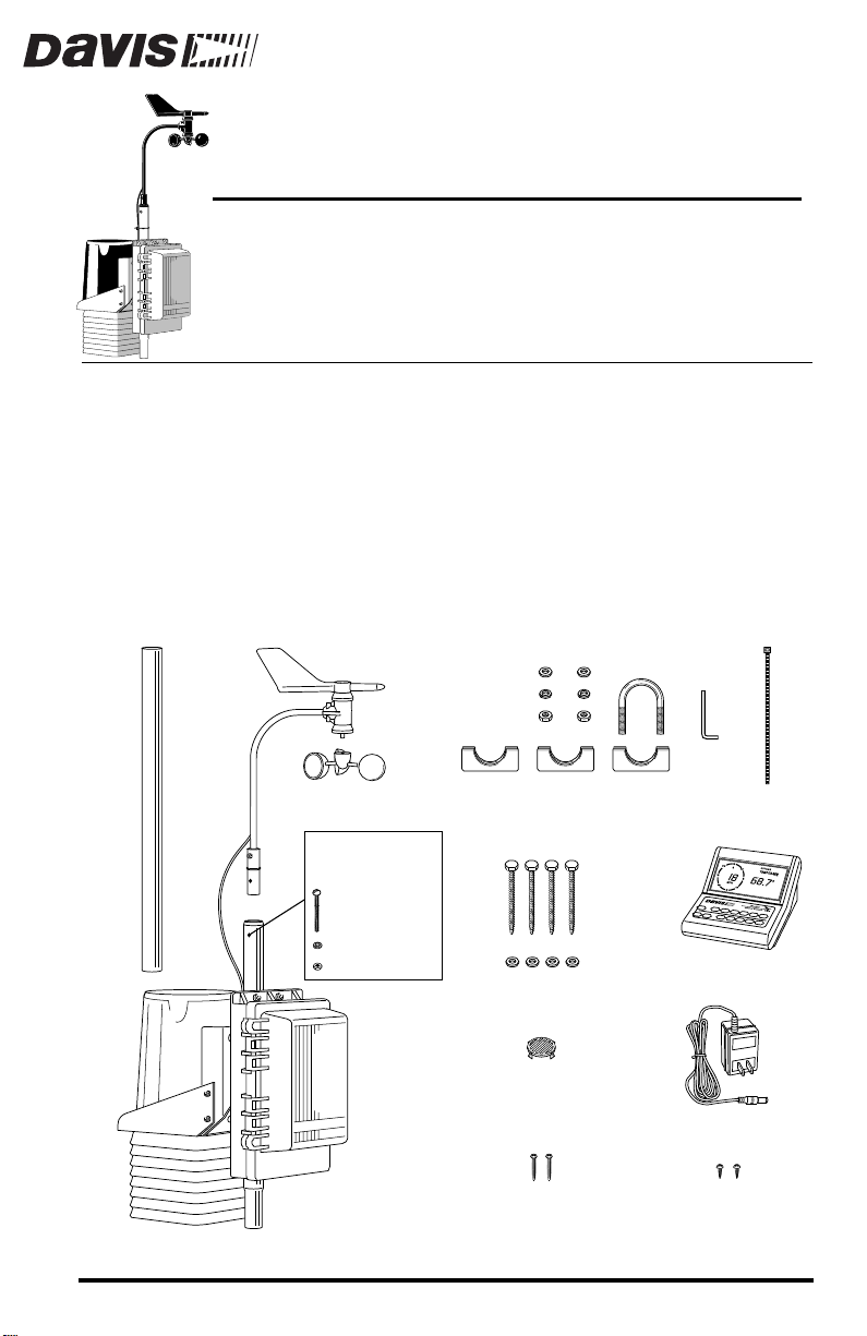
The EZ-Mount weather station includes the following components. Please
make sure you have everything you need before beginning.
Rain
Collector
Cone
Extension
Tube
Anemometer
Wind Cups
This hardware
comes installed
on Sensor Array:
#12 x 1-1/2"
Pan Head Screw
#12 Lock Washer
#12 Hex Nut
Field Case
Weather Station
Sensor Array
[100' (30 m)
8-Conductor Cable
Not Shown]
5/16" Flat Washers
5/16" Lock Washers
5/16" Hex Nuts
1-1/8"
Saddles
5/16" x 3"
Lag Screws
Flat Washers
Debris Screen
(place inside
Rain Collector Cone
after installation)
#8 x 3/4"
Pan Head Screws
(for mounting Console
5/16"
on wall)
5/16" x 1-1/2"
U-Bolt
Weather Station Console
Pan Head Screws
(for mounting Console
on Field Case door)
Cable
Tie
Allen
Wrench
Power Adapter
#6 x 1/4"
Product # 7425EZ, 7440EZ, (EU, UK, M)
Page 2

OOLS AND MATERIALS NEEDED
T
In addition to the components listed above, you may need some of the following tools and materials.
Flat-Bladed Screwdriver
✦
Phillips Screwdriver
✦
✦
Adjustable Wrench
Wire Cutter or Scissors
✦
Electrical Tape
✦
✦
Cable Clips or Weather Resistant Cable Ties
With screw holes and screws or other means for mounting
Hammer
✦
I
NSTALLATION
S
TEPS
This manual takes you through the step-by-step process of installing your
weather station. These steps are indicated below, along with their page numbers for easy reference:
✦
Assemble and test the station, page 3
✦
Detach the extension tube, page 3
✦
Attach the anemometer, page 3
✦
Attach the wind cups, page 3
✦
Snip the cable tie in the rain collector, page 4
Apply power to the console, page 4
✦
Plug cable from sensor array into console, page 5
✦
Check that the console and sensors are working properly, page 5
✦
Re-attach rain collector cone and unplug sensor array cable from
✦
console, page 5
✦
Install the station, page 5
Choose locations for the sensor array and console, page 5
✦
Mount and secure the sensor array, page 5
✦
Run sensor array cable to console, page 7
✦
Mount the console, page 7
✦
If, once installed, you encounter any problems with the station, please refer to
the troubleshooting guide on page 8 or call our technical support line for assistance.
Page 2 EZ-Mount Weather Station
Page 3
ETTING
G
TARTED
S
Follow the steps below to install your station. At various stages of this installation, you will be advised to test the system to ensure proper functioning.
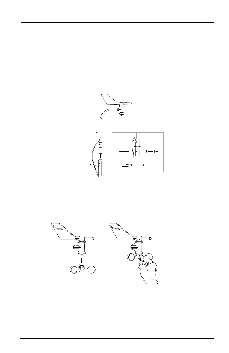
1. Detach and remove the extension tube from the support tube by cutting the two
black cable ties.
2. Attach the anemometer arm to the support tube as shown below. Make sure that the
anemometer is positioned over the white field case and NOT over the black rain collector cone.
Anemometer
Anemometer Arm
Lock
Washer
Cable Tie
Hex
Nut
Anemometer
Cable
Support Tube
#12 x 1-1/2"
Screw
3. Attach the wind cups to the anemometer.
Push the wind cups onto the shaft as far as they will go, then tighten the set
screw. The cups should drop slightly and into the ideal position automatically. Spin the wind cups. If they do not spin freely, loosen the set screw and
lower the cups slightly. Repeat until the wind cups spin freely.
a. Push cups onto
stainless steel shaft
Getting Started Page 3
b. Tighten set screw
with allen wrench
Page 4

4. Detach the rain collector cone and snip the cable tie.
Detach the black rain collector cone from its base by rotating the cone
counter-clockwise until its latches line up with the latch openings in the base
and then lift the cone off. (The cone fits tightly and may require extra pressure to remove it the first time.) C
which holds the bucket in place during shipping.
Twist off the rain collector cone.
arefully cut and remove the black cable tie
Snip the black cable tie.
Do not re-attach the rain collector cone at this point; you will need to test the
tipping bucket before you complete the installation.
5. Apply power to the station console.
To power up the console, first remove the console’s mounting base by pressing down on the large tab between the two oblong holes on the base’s
underside and pulling the base free. Plug the power adapter into the center
“Power” slot, as shown below, and then plug the other end into a 110 VAC
outlet. Once power is applied, the console should beep twice within 10 seconds if the console is working properly. (If you have the optional WeatherLink installed, the console should beep three times within 20 seconds.) The
readings will appear dashed out until you connect the sensors.
Note: If you are going to use a battery as backup, make sure that you plug in the AC power before
installing the battery . Powering up the console with the battery alone may cause the console
to lock up due to insufficient power. (Do NOT use a backup battery if you use the optional
EZ-Solar Power Kit.)
Console
Power Adapter
Base
AC Power
Outlet
Page 4 EZ-Mount Weather Station
Page 5

6. Connect the sensor array field case to the console.
Plug the free end of the 100’ (30 m) 8-conductor cable on the sensor array
into the jack labeled JUNCTION BOX underneath the console.
The pre-assembled EZ-Mount station allows you to install your station
without ever opening the sensor array field case (the white rectangular
box). Inside the field case, the sensor data passes through a junction box
then out to the console through the cable.
7. Check all of the readings on your display to be sure they appear correctly (i.e., not
dashed out).
Consult your Monitor or Wizard owner’s manual for instructions on displaying the various readings. Spin the wind cups, move the wind vane, and
tip the rain bucket to verify wind speed and direction and rainfall readings.
Note that some sensor readings (e.g., wind direction, barometer, and 0.2mm
rain collectors) must be adjusted in order to read correctly; specific instructions are contained in the owner’s manual.
If the console is having problems reading the sensors, consult the troubleshooting guide at the end of this manual.
8. Re-attach the rain collector cone and lay the debris screen “feet-down” over the
cone’s funnel hole.
9. Unplug the console end of the 8-conductor cable.
NSTALLING
I
Choosing Locations for the Sensor Array and Console
The cable that connects your sensor array to your console is 100 feet (30 m)
long. Choose a location where the cable can safely and reasonably connect
with the console. Most people install the sensor array on the roofs of their
houses, on fences, or in open fields where wind flow and rainfall are unobstructed by trees and nearby buildings, and then install their consoles inside
their houses.
Alternatively, you can mount the console in the field case on the sensor array
itself and either check the data at the site, or use the optional W eatherLink and
run a cable to a computer. If you plan to mount the console inside the field
case, please keep in mind that you will need to supply the console with
uous
other 110 VAC,
Note: The 9-volt backup battery can serve this purpose temporarily but is not recommended as a
For an illustration of how to mount the console on the inside door of the field
case, refer to the Multi-Purpose Shelter manual included with your station.
Installing Your Station Page 5
OUR
Y
power. To do this, you can use the optional EZ-Solar Power Kit or any
long-term solution—a new battery will power the station for 24-48 hours only.
TATION
S
weather-protected
contin-
power source.
Page 6

Mounting the Sensor Array
The sensor array has been pre-assembled for easy installation. However, you
will still need to provide a solid mounting for the sensor array. Mounting hardware has been included for the most common installations (see figures below).
If you are using the optional Mounting Tripod, consult the tripod’s manual for
mounting instructions.
CAUTION: The station’s wind direction is calibrated as if the horizontal part of the anemometer arm
were pointing south. If you plan to mount the station facing a different direction, consult
your owner’s manual for instructions on how to adjust the wind vane accordingly.
MOUNTING ON A FENCE MOUNTING ON A POST
Sensor Array
Sensor Array
Support Tube
(swaged end)
Extension Tube
(see fence mounting for details)
4 x 4
treated
post,
8' long
2' of
post
buried
Use post hole
digger, fill hole
with post hole
concrete
12"
minimum
1-1/8" Saddle
5/16" Flat Washer
5/16" x 3" Lag Screw
Extension Tube
(21" long, no swaged end)
Note: For roof mounting, we recommend the optional Mounting Tripod. If mounting on a roof, tower, or
other elevated structure without the Tripod, be sure to consider the effects of lightning, wind
loading and vibration and design the installation accordingly.
Page 6 EZ-Mount Weather Station
Page 7

N
Securing the Sensor Array
After mounting the sensor array, secure the sensor array to the extension tube
as shown below.
Array
Hex
uts
Lock
Washers
Flat
Washers
1-1/8"
Saddles
2-1/2"
1-1/2" x 5/16" U-Bolts;
torque until bolts dent
tubing slightly
Running the Cable to the Console
To prevent fraying or cutting of the 8-conductor cable, secure the cable so it
does not whip about in the wind. Secure it to the extension tube by wrapping
electrical tape around them both. Use cable clips or weather resistant cable ties
(see owner’s manual for illustration) to secure the cable underneath the eaves
of your house or in locations similarly shielded from rain. Make sure the cable
is secure by placing clips or ties approximately every 3-5 feet (1-1.6 m).
Note: Do not use metal staples or a staple gun to secure the cable. Metal staples—especially when
installed with a staple gun—have a tendency to cut the cables.
Mounting the Console
1. Plug the 8-conductor cable into the JUNCTION BOX jack on the console (step 6 on
page 5).
2. Apply power to the console (step 5 on page 4).
3. For instructions on installing a backup battery, refer to your owner’s manual.
If you plan to use an EZ-Solar Power Kit, do NOT install a backup battery.
4. For instructions on mounting the console on a wall, desk, or shelf, refer to your
owner’s manual. Or, if you want to mount the console inside the field case, see the
discussion on page 5.
Installing Your Station Page 7
Page 8

ROUBLESHOOTING
T
While the EZ-Mount weather station is designed to provide years of troublefree operation, occasional problems may arise. If you experience a problem,
please check the troubleshooting tips below before calling tech support.
Console does not register any rainfall
✦
Double check that you have cut the cable tie that secures the rain bucket
during shipping. See step 4 on page 4 for instructions. Also, make sure the
anemometer is not positioned above the rain collector cone.
Console does not register wind direction correctly
✦
Check that you have either pointed the anemometer arm southward when
mounting (page 5), or that you have recalibrated the console to the anemometer arm’s current direction. See the “Installing the Anemometer” section of your owner’s manual for instructions on how to adjust the wind
vane so that the anemometer and the console are in sync.
✦
Console locks up
Insufficient power during power up or a power surge may cause the console to lock up. If this occurs, remove all power by disconnecting any battery backup and the
power removed. Then re-connect the
power cord. Wait for 1 minute with all of the
AC/DC
AC/DC
power cord and listen for 2
beeps within 10 seconds.
Note: If you have the WeatherLink installed, listen for 3 beeps within 20 seconds and then, if all
is well, try communicating with the WeatherLink using the software.
Once you receive the final beep, install a fresh backup battery, if desired,
and put the console back into service.
✦
Other problems
Check the troubleshooting guide in the back of your owner’s manual for
help with many of the most common problems.
If, after checking this troubleshooting guide and the one in your owner’s manual, you are unable to solve the problem, please call our technical support team
at (510) 732-7814 for assistance (M-F, 7 am–5:30 pm PST). Please do not return
your unit for repair without prior authorization.
Product Numbers: 7425EZ, 7440EZ, (EU, UK, M)
Davis Instruments Part Number: 7395-302
EZ-Mount Weather Station Installation Manual
Rev. C Manual (7/8/99) Controlled online: Weather Manuals/Consoles/EZ/EZ-Mount
This product complies with the essential protection requirements of the EC EMC Directive 89/336/EC.
© Davis Instruments Corp. 1998. All rights reserved.
Weather Monitor II, Weather Wizard III, and WeatherLink are registered trademarks of Davis Instruments Corp.
3465 Diablo Avenue, Hayward, CA 94545-2778
510-732-9229 • Fax: 510-732-9188
E-mail: info@davisnet.com • www.davisnet.com
 Loading...