

Page 1

WeatherLink® for Irrigation Control
Addendum
Introduction
This Data Logger is designed for use with most common irrigation systems,
including those provided by Rain Bird, Rain Master, and Toro. For the
industrial controllers used in agriculture and turf management, it provides
electronic pulse outputs for wind, rain, and evapotranspiration (ET).
Homeowners can add our optional solar radiation sensor to their
VantagePro™ weather station to turn their irrigation system on or off based
on evapotranspiration. All users can use the alarm settings in the Vantage
Pro™ console or Weather Envoy™ to inhibit the irrigation cycle based on
weather conditions. The data logger will inhibit th e ir ri gation cycle if ANY
of the alarms are active.
This product also contains the functionality of the WeatherLink for Vantage
Pro Serial version. Please consult the WeatherLink for Vantage Pro™
Getting Started Guide and on-line Help files for information on the use of the
WeatherLink
installation), package contents, and optional accessories for this product.
If you plan to install this product in a Vantage Pro™ console, use the notch
in the Battery Door located adjacent to where the PC connector protrudes and
above the AC power connector to bring out the Connector Block wire.
If you plan to install this product in a Weather Envoy™, it is recommended
that you knock out the left-most tab with the Weather Envoy’s PC connector
facing you and loop the Connector Block wire around the datalogger
connector to the Weather Envoy™ and bring it out where this tab was
removed.
Hardware Installation and Requirements
In addition to the requirements for Wea the rLink , the Irrig ation cap abi lity of
this product has the following additional hardware requirements.
• One Free Serial Port or One Free USB port with the Serial to USB
• Computer running any version of Windows™ with at least 3 MB
®
program (including its hardware requirements and typical
adapter (Part # 8434) connected to a Windows PC.
free of RAM and 512 KB free of hard disk space.
1
Page 2

• Industrial Irrigation Controller with inputs for wind, rain, and/or ET;
or a Residential Controller with a Common or a Rain Sensor
connection. Irrigation wire as appropriate to your Irrigation
Controller
• Solar Radiation Sensor, P/N 6450 to use evapotranspiration (ET) to
control the irrigation cycle. In addition to the ET pulse output, the
Rain – ET algorithm uses this inform ation. More info rmation is
provided below.
• Small Slotted Screwdriver
• Relays: You may need to obtain your own relays in order to switch
equipment at voltages higher than 28 Volts or power levels above 10
Watts.
Note 1: Your Residential Irrigation Controller may be connected in series to
both the ET and Alarm inputs on the Irrigation datalogger if you wish the
Irrigation system to also be suspended due to, say, high winds or cold
temperatures, for example, in addition to the Rain/ET balance.
Note 2: Due to its normal operation, this product will draw more current
from the Vantage Pro™ Console and Weather Envoy™ than in typical use.
Davis recommends you use the power adapter provided with your product if
you are concerned about battery life.
Software Installation and Setup
Installing the Software
Follow the installation instr uct ions for We ath erL ink®. This will also install
the configuration software. The install disc contains this program as well as
WeatherLink
Running the Configuration Software
To run the configuration software, double-click on the Streaming Data Utility
icon in the Streaming Data Utility directory of the WeatherLink
select the Streaming Data Utility from the Start Menu under the
WeatherLink
®
if you ever need to install the program manually.
®
directory.
®
directory or
2
Page 3
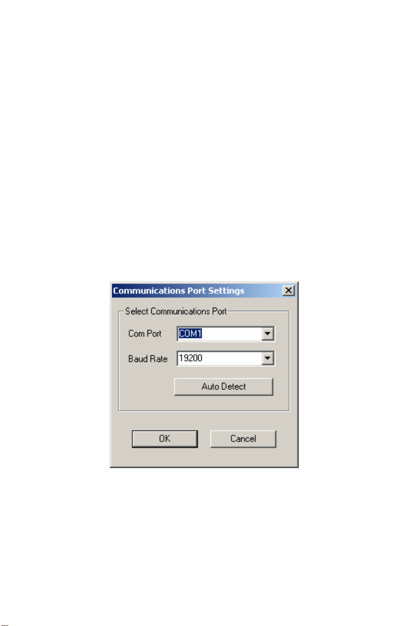
Finding the Correct Serial Port
The configuration software includes a procedure for locating the serial port to
which your streaming data logger is connected or determining whether that
serial port is working.
Note: Using the Auto Detect command in WeatherLink
the serial port. The Loopback command will help you determine whether the
serial port is functioning. Consult the WeatherLink
Getting Started Guide and on-line Help files for more information.
Use the Serial Port Settings dialog box to select the correct COM port and
baud rate to communicate to the streaming data logger. The correct baud rate
will be the one set in your Vantage Console, and in WeatherLink. The
default value is 19200 baud. You may manually set the COM port setting or
use the Auto Detect button to automatically find where your streaming data
logger is connected.
®
can help you locate
®
for Vantage Pro™
Note: If you have more than one streaming data logger connected to your
system, it is highly recommended that you manually set the com port and
baud rate.
3
Page 4
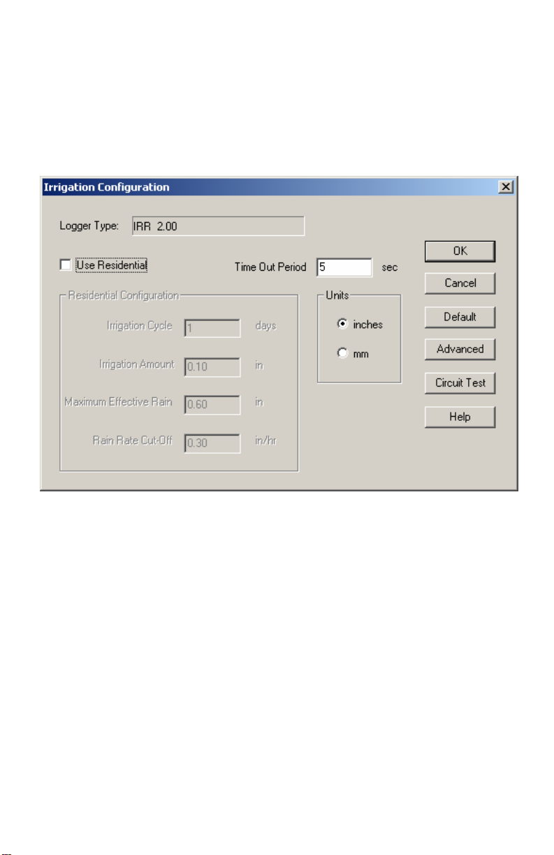
Logger Type
The software indicates the logger type and firmware revision level of the
streaming data logger in the logger type box.
4
Page 5

Time Out Period
Normally, the Irrigation data logger will send pulse data to an Automated
Irrigation Sprinkler System Controller. However, the Irrigation data logger
utilizes a time-out period for ceasing Irrigation functions whenever software
attempts to communicate to the logger. The default setting is 5 seconds.
You may adjust this value if you wish Irrigation functions to resume sooner
or later after communicating to the logger using WeatherLink
®
or the
Streaming Data Utility.
Note: Once communications to WeatherLink are initiated and successful, the
streaming data logger will be unable to com municate with the Streaming
Data Utility until the Time Out Period expires. If you need to communicate
to the logger with both the Streaming Data Utility and WeatherLink
®
, you
should communicate using the Streaming Data Utility first.
Use Residential
Check this dialog box if you choose to use the Irrigation data logger with a
Residential Irrigation System Controller to inhibit the watering cycle. This
type of sprinkler controller will be what is typically installed by most
homeowners and will have inputs for a Common and in many cases a Rain
Sensor. See the Installation section below for installation instructions.
Do NOT check this box if you are using this product in an Industrial
application where the controller has inputs for wind, rain and/or ET.
Units
Choose whether you want to enter your Rain and ET values in inches or
millimeters. This will not affect how the rain or ET outputs function. The
Rain will still output according to the rain collector type and ET will always
output every 0.01 inch.
5
Page 6

Advanced
The following functions apply to the alarm output:
Delay on Release
Use this function in conjunction with the Alarm output and the Vantage Pro
alarms to determine how long to extend the activitation time once it is
triggered. The default value is 10 minutes.
Delay on Reactivation
Use this function in conjunction with the Alarm output and the Vantage Pro
alarms to determine how long to delay the reactivation of an alarm once it is
inactive. The default value is zero.
Pulse Width
This function determines the pulse width for any pulse outputs. These
outputs include the Rain, ET and Alarm outputs. The default value is 2000
milliseconds (2 seconds). In the case of consecutive pulses, it also
6
Page 7

determines the time between pulses. In most cases, there is no need to alter
this value unless directed to do so by the Irrigation controller manufacturer.
Alarm Activation
This command determines whether a pulse for alarm activation is continuous
throughout the activation time or a one time pulse. The default is continuous
activation and is appropriate for most Irrigation controllers. Pulsed relay
oriented devices will require the one-time pulse.
Circuit Behavior
This command determines whether the circuit stays open or closed when no
alarms are active. The opposite behavior occurs for an active alarm
condition. Default is normally closed. Choose normally open if you want
the irrigation controller to inhibit the system unless an alarm condition
occurs. Choose normally closed if you want the irrigation controller to run
its normal cycle unless an alarm condition occurs (This is the most typical
operation.).
Circuit Test
Pressing the Circuit Test button puts the Irrigation data logger into Circuit
Test mode. In this mode, all other functions of the data logger cease. Do not
press this button unless you wish to perform a test because it may disrupt the
behavior of your Irrigation system.
This function is used to test the output of the Irrigation logger. Push the
button of the output you want to test (Wind, Rain, ET, or Alarm). The button
7
Page 8

will be depressed to indicate Closed circuit mode and raised to indicate Open
circuit mode. To utilize this function effectively, you will need to connect a
device to the appropriate output so that you can tell whether it is turning on
or off.
You can connect a voltmeter or continuity tester to the outputs and see if the
output changes state (high for closed or low for open). You may also
connect your irrigation controller to one or more of the outputs. If you utilize
Industrial mode, check to see that the controller receives the data correctly
(Rain, ET and/or Wind pulses). If you use Residential mode, put your
controller in manual mode and run the sprinklers and check to see that the
sprinklers run when the ET circuit is closed and doesn’t run when the ET
circuit is open. Additionally, if you wire the alarm circuit to the irrigation
controller, you can check to see if the sprinklers run with the Alarm circuit
closed or fail to run with the Alarm circuit open. When wired in series with
the ET function either the ET function or the Alarm function should cause
the same behavior when either of the circuits is closed (or open). When
wired in parallel, both circuits must be closed (or open) to cause the same
behavior.
To leave this mode, simply exit the dialog box by pressing the OK button.
You must hit OK in the main dialog box to return the datalog g er to its
original settings.
Default
Press this button to restore the data entries to their default values. You must
still hit OK to save the settings in the data logger.
Residential Configuration
This function is designed to inhibit the irrigation cycle when sufficient
rainfall and/or irrigation has occurred to make up for any ET loss over the
past irrigation cycle. In this mode, the Irrigation data logger calculates Rain
minus ET every cycle to get the net result, much like balancing a checkbook.
In this manner, Rain can be thought of as deposits, and ET as withdrawals.
However, unlike a checking account, this number can run negative. In this
case, deposits of rain from irrigation need to be entered to make the net
balance zero again. The Irrigation Amount you enter into the dialog box (see
below) is applied at the end of each cycle when the data logger allows the
8
Page 9

irrigation system to run. Positive numbers in the balance indicate more rain
and irrigation than ET; negative numbers indicate more ET than rain and
irrigation has occurred over the irrigation cycle. If the value is negative, then
it indicates that watering needs to occur to make up for the deficit that
rainfall has not made up. Please note that this difference only updates once
per every cycle, thus there will be a cycle-long delay in the system
responding to rain. Also, the irrigation system will be enabled upon power
up until the first Irrigation Cycle has completed.
The following functions are only available in the Residential mode with “Use
Residential” checked:
Irrigation Cycle
Indicate the length of your entire watering cycle in days. The irrigation data
logger determines for the duration of each cycle whether or not to allow the
irrigation system to run. The default value is 1 and represents a daily
watering cycle. This value is used to determine over what period to calculate
the Rain – ET balance. Enter a value of 2, for example, if your watering
cycle is every other day. If your schedule is a Monday, Wednesday, Friday
schedule, for example, you can either use the most frequent watering interval
9
Page 10

of 3 days (Friday – Monday) or a weekly watering period (7 days). Since
most ET occurs during the day on a daily basis, using these values will
provide the most consistent results with your irrigation system. Your
watering cycle should represent the period of time it takes for all your
programmed cycles on your irrigation controller to start, finish and then
begin again. If you have some circuits on a 2 day cycle, and others on a 3
day cycle, it is recommended that you enter the longest of all the cycles you
use. In this case, enter 3 days. Please note that altering this value restarts the
cycle.
Irrigation Amount
Enter the amount of water in inches that your Irrigation system puts out
during one cycle. The cycle should be defined as recommended in the
previous paragraph. Typically, placing several cans around your lawn, and
measuring the depth of water in the cans with a ruler will provide you with
the Irrigation Amount for that location. Average all the locations to get the
number to enter into this dialog box. Since the Vantage Pro™ Console or
Weather Envoy™ calculates reference ET over regularly mowed grass, it is
best to enter the lawn sprinkler value. Consult your Vantage Pro™ Console
or Weather Envoy™ Manual for more information on ET.
Maximum Effective Rain
This function puts a “cap” on the amount of rain that is counted towa rd the
balance between Rain and ET. The amount entered in this dialog box
represents the total amount of rain during a 24 hour period that is counted. A
value of zero in this dialog box disables this function, so that all rain is
counted toward the Rain minus ET balance.
Rain Rate Cutoff
This function can be used to inhibit the irrigation cycle in the case where the
ET deficit has not been made up by rainfall, but rainfall is occurring at a high
enough rate that the combination of rainfall and irrigation may cause runoff
and thus waste water. The default value is 0.30”/hour, which represent a
heavy rain rate. Rain rate is an instantaneous calculation. Consult your
Vantage Pro™ Console or Weather Envoy™ Manual for more information
on Rain Rate. Once this function goes into effect, it inhibits the sy stem until
the rain rate reaches zero, which is when it has stopped raining for at least 15
10
Page 11

minutes. If you want your irrigation system to immediately stop watering
whenever any rain occurs, set the Rain Rate Cut-Off value to 0.01” (0.1 mm)
(see below). Note that 0.02” or 0.4 mm of rain must accumulate before a
rain rate is calculated.
Irrigation Connector Block Installation
For an Industrial installation, connect the Wind, Rain, and ET connections to
the corresponding connections (if available) on the Industrial Irrigation
Controller. Consult the Controller’s manual for details. The wind output
generates a frequency equal to the wind speed in mph over a 2 second period.
Thus, the frequency in Hz is half the wind speed. The rain output generates a
pulse for every tip of the rain collector, which will either be 0.01” or 0.2 mm
depending upon the rain collector type. Consult your Vantage Pro Console
Manual for details. ET output generates a pulse for every 0.01” of ET.
To use the Residential function, connect the ET connection of the irrigation
connector block to the Rain Sensor or in series with Common connection on
the Irrigation Controller.
11
Page 12

To use the Alarm output function, connect the Alarm connection of the
irrigation connector block to the Rain Sensor or Common connection on the
Sprinkler Controller. This function will work with any properly equipped
Irrigation controller even in Residential mode.
12
Page 13

Contact Specifications
The “contact” closure is provided by a photo-coupled MOS device. Because
it is a solid-state device, it is not subject to arcing and contact-welding as are
mechanical relays. However, since it is a solid-state device, it will be
damaged by operation beyond its ratings, which are:
Nominal Load Voltage: 28 V AC or 48 V DC, Maximum
Peak Voltage: ± 60 V, Maximum
Load Current: ± 1.8 A, continuous Maximum at 77°F (25°C),
derated to 0.7 A at 185°F (85°C)
ON Resistance: 0.12 Ohm, Maximum
Note: Upon power up (powering the Vantage Pro Console™ or Weather
Envoy™), the datalogger will briefly test all four outputs by closing the
circuit (turning on the output). It is recommended that you disconnect any
equipment attached to the datalogger outputs before rebooting the Vantage
Pro Console™ or Weather Envoy™.
13
Page 14

14
Page 15

15
Page 16

Product Number: 06560
Davis Instruments Part Number: 07395.216
WeatherLink for Irrigation Control
Rev B Addendum (3/5/07)
16
 Loading...