

Page 1
Page 2

Product Number: 7862 Part Number: 7395.179
WeatherLink
®
for Weather Monitor II®, Weather Wizard III®, and Perception II® Rev. C September 29, 2009
WeatherLink, Weather Monitor II, Weather Wizard III, and Perception II are trademarks of Davis Instruments
Corp. Hayes is a registered trademark of Hayes Microcomputer Products, Inc. Windows is a trademark of
Microsoft Corporation.
© 2009 Davis Instruments Corp. All rights reserved.
Information in this document is subject to change without notice.
3465 Diablo Avenue, Hayward, CA 94545-2778 U.S.A.
510-732-9229 • Fax: 510-732-9188
E-mail: info@davisnet.com • www.davisnet.com
FCC Part 15 Class B Registration Warning
This equipment has been tested and found to comply with the limits for a Class B digital device, pursuant to
Part 15 of the FCC Rules. These limits are designed to provide reasonable protection against harmful interference in a residential installation. This equipment generates, uses and can radiate radio frequency energy and,
if not installed and used in accordance with the instructions, may cause harmful interference to radio communications. However, there is no guarantee that interference will not occur in a particular installation. If this equipment does cause harmful interference to radio or television reception, which can be determined by turning the
equipment on and off, the user is encouraged to try to correct the interference by one or more of the following
measures:
• Reorient or relocate the receiving antenna
• Increase the separation between the equipment and receiver
• Connect the equipment into an outlet on a circuit different from that to which the receiver is connected
• Consult the dealer or an experienced radio/TV technician for help.
Changes or modifications not expressly approved in writing by Davis Instruments may void the user’s authority
to operate this equipment.
EC EMC Compliance
This product complies with the essential protection requirements of the EC EMC Directive 89/336/EC.
Page 3

1
Welcome to WeatherLink!
Welcome to Davis Instruments’ WeatherLink for Windows. WeatherLink’s data
logger and software connects a personal computer to your Davis weather station,
allowing you to store, view, plot, analyze, export, and print your weather data.
The following Davis Instruments’ weather stations are supported: Weather Mon-
itor II
®
, Weather Wizard III®, and Perception II®.
Contents of Package
Before continuing, please make sure your WeatherLink package contains the
following listed items:
• Data Logger for Monitor, Wizard and Perception
•9-pin (DB-9) PC COM Port Adapter (black) — Use the 9-pin adapter to
connect the data logger to a 9-pin serial port.
Note: If you need a 25-pin adapter, contact Davis Instruments Technical Support at
510-732-7814.
• Loopback Connector — The loopback connector is a short piece of cable
with a phone plug at one end and a red plastic cap at the other.
• WeatherLink Software CD ROM
Optional Accessories
The following optional accessories, designed for use with WeatherLink, are
available from your dealer or may be ordered directly from Davis.
• Telephone Modem Adapter (# 7870) — For transmission of data from the
data logger using a modem.
• Standard 4-Conductor Extension Cable (# 7876) — For more flexibility in
the placement of your console. Add one 40' (12 m) extension cable to extend
the distance between your station and the computer (48' (14.4 m) maximum).
• USB-to-Serial Cable (# 8434) — For computers with no serial port. Allows
you to convert the console’s serial connection to a USB interface.
Hardware Installation
You can either install WeatherLink to create a local connection between your
computer and weather station, or you can install WeatherLink to use a modem
connection to a remote weather station. Requirements and installation for each
type of connection differ, and are explained separately below.
Page 4

2
Software Installation
Local Connection Hardware Requirements
The following additional hardware is required for a local connection:
• Computer running Windows™ 2000, XP, or Vista and requires 5 MB of
free disk space.
Note: The .NET framework is required to run WeatherLink 5.8 or later. It is installed as part of
the software installation if it is not already on your computer.
The amount of disk space necessary depends on the archive interval.
Database files containing data stored at a 30 minute archive interval
require approximately 132K of disk space per month of data. The file size
changes in a linear fashion depending on the archive interval. For example,
data stored at a 1–minute interval requires approximately 3.9 MB per
month while the data stored at a 2–hour interval requires approximately
33 KB per month.
• Windows-Compatible Display — VGA minimum. SVGA or High (16-
bit) Color recommended.
• One free serial port or USB Port with USB-to-Serial cable.
Remote Modem Connection Hardware Requirements
In addition to the provided hardware and the computer equipment listed above,
the following hardware is required for a remote modem connection.
• One external modem to connect to the data logger at the remote site.
• One internal or external modem connected to your computer
• Modems must be Hayes
®
Compatible and able to send data at 1200 or 2400
baud rate.
• Telephone Modem Adapter — The Telephone Modem Adapter is
specially wired to provide the connection between the data logger and the
modem. Use a # 7870 adapter.
Note: See the Application Note entitled “Setting up a Remote Modem Connection” located on
the Weather Support section of the Davis website:
http://www.davisnet.com/support/weather/.
Software Installation
Follow the steps below to install the WeatherLink software.
1. Place the WeatherLink software CD in your CD ROM drive.
The install program should start automatically. If the install program does
not start, select Run from the Start menu, type D:\SETUP (or the correct
letter for your CD ROM drive), and click OK to begin the installation.
Page 5
3
Software Installation
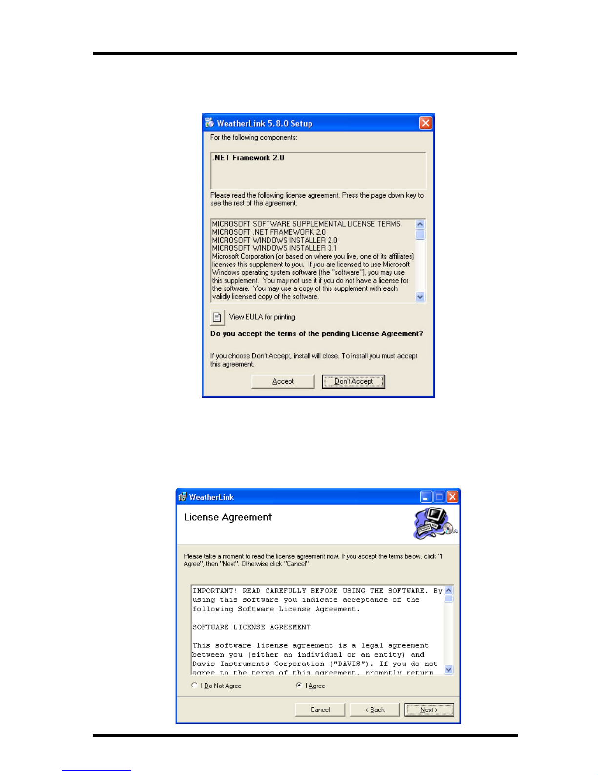
A series of dialog boxes display, prompting you to complete the
WeatherLink installation. The WeatherLink Setup for .NET Framework
dialog box may display.
WeatherLink 5.8 requires the Microsoft .NET Framework 2.0 to operate. If
your computer does not have it installed, the above dialog box displays.
2. Click Accept to install the necessary components.
The License Agreement dialog box displays.
Page 6
4
Local Connection Installation
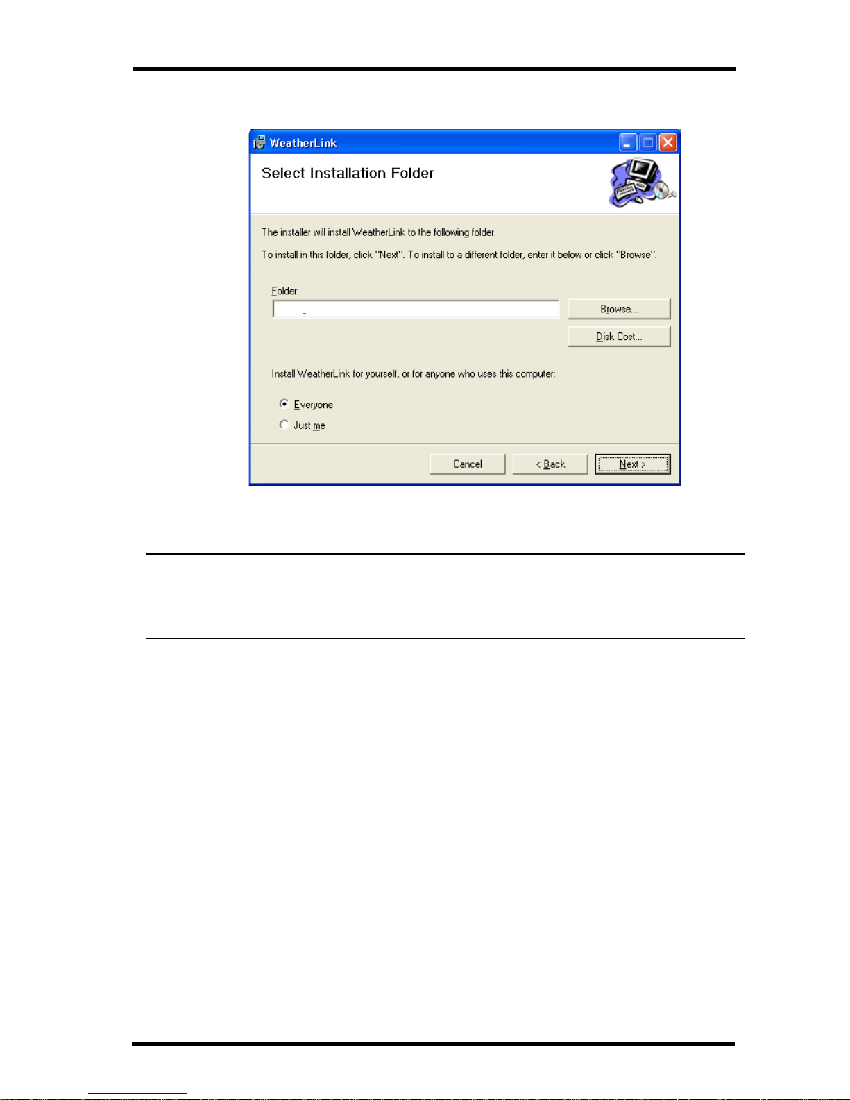
3. Review the license agreement, click I agree and click Next. The Choose
Destination Location dialog box displays.
4. Select the default location to install WeatherLink or find another location
by clicking Browse.
Note: If you are upgrading your software from a previous version, click Browse to search for
the directory or folder of the previous version of WeatherLink. This verifies that you have
a previous version of WeatherLink installed and allows you to use those available
database files.
5. Click Next once you have selected a location. The Confirm Installation
dialog box displays.
6. Click Next to start the installation. The Installing WeatherLink dialog
box displays the installation progress. The Installation Successful dialog
box displays once the software installation has been completed.
7. Click OK. WeatherLink has been installed successfully.
Local Connection Installation
The instructions below explain how to connect your Weather Monitor II,
Weather Wizard III, or Perception II weather station directly to your computer.
C:\WeatherLink\
Page 7

5
Local Connection Installation
1. Make a note of the barometric pressure, total rainfall, and (if applicable)
calibration numbers.
You must remove power from the weather station console to install the
data logger. Removing power will cause these stored weather values to be
erased. Use WeatherLink to reenter these values after restoring power to
the console.
2. Remove the mounting base from the console.
3. Remove all power from the console by removing the power adapter and
battery backup.
Failure to remove power before installing the data logger may cause
damage to the data logger and/or console.
4. A small switch near the data logger cables controls the baud rate. The
default setting is 2400 baud. If you need to run at 1200 baud, change the
setting before connecting the data logger to the console.
5. Connect the short data logger cable to the cable jack marked
“WeatherLink” on the bottom of your weather station console.
6. Restore power to the console by reattaching the power adapter and listen
for the console to emit beeps.
The console should beep three times. The third beep, which should occur
within 30 seconds, indicates that the data logger is operating correctly.
After hearing the three beeps, re-install the battery backup.
Typical Local Connection for Original Weather Stations
Page 8

6
Remote Connection Installation
7. Place the data logger inside the
mounting base.
8. Reattach the mounting base to the
weather station.
As you do so, guide all the cables
through the slots on the mounting base.
9. Locate a free serial port on the back of
your computer and connect the black
DB9 adapter to the port or use the
USB-to-Serial cable to connect to a free
USB Port.
10. Connect the long data logger cable to
the DB9 adapter connector.
The cable connecting the data logger to the computer is 8' (2.4 m) long. If
you need to place the station console more than 8' from the computer, use
the 40' (12 m) 4-conductor extension cable (# 7876-040).
Note: Do not attempt to use more than 40’ of extension cable, or the data logger may have
difficulty communicating with the computer. Do not attempt to use 4-conductor telephone
cable because telephone cable will not work with the connection.
Remote Connection Installation
You can connect your computer to a remote weather station using a modem.
This involves using the data logger to connect the weather station console to a
modem at the remote site. Your computer can then use a modem to
communicate to the remote weather station via a phone line.
At Your Computer:
1. If you don’t have a modem, install and set up an internal or external
modem according to the instructions supplied by the manufacturer.
2. Connect the modem to the phone line.
At Your Weather Station Console:
1. Make a note of the barometric pressure, total rainfall, and (if applicable)
calibration numbers.
You must remove power from the weather station to install the
WeatherLink data logger, which will cause these values to be erased. Use
WeatherLink to reenter these values after restoring power to the station.
2. Place the external modem in a location where it can connect to both the
data logger and the phone jack. Do not turn the modem on at this time.
3. Remove the mounting base from the weather station.
4. Remove all power from the weather station by removing the power adapter
and battery backup.
Placing Data Logger Inside Base
Page 9

7
Remote Connection Installation
Failure to remove power before installing the data logger may cause damage to the data logger and/or station.
5. A small switch on the data logger near the cables controls the baud rate.
The default setting is 2400 baud. If you need to run at 1200 baud, change
the setting before connecting the data logger to the console.
6. Connect the short data logger cable to the cable jack marked “WeatherLink” on the bottom of your weather station console.
7. Connect the blue Telephone Modem Adapter to the external modem.
The Telephone Modem Adapter (#7870) is required to use the data logger
with a modem. A standard DB25 connector with a gender changer will not
work.
8. Connect the long data logger cable to the Telephone Modem Adapter.
9. Turn the modem on.
10. Restore power to the weather station console by reattaching the power
adapter and listen for the console to emit beeps.
The console should beep three times. The third beep, which should occur
within 30 seconds, indicates that the data logger is operating correctly.
After hearing the three beeps, re-install the battery backup.
Typical Remote Installation for Original Weather Stations
Page 10

8
Remote Modem Connection Notes
11. Place the data logger inside the mounting base.
12. Reattach the mounting base to the
weather station.
As you do so, guide all the cables
through the slots on the mounting base.
Remote Modem Connection Notes
When accessing a remote modem connection, WeatherLink automatically
dials the station and console whenever an action has been performed in the
software that requires it to talk to the station.
While connected to a remote station, an On-Line icon displays in the tool bar.
This icon indicates that WeatherLink has established a connection with the
remote console and weather station.
To disconnect the phone connection, select the On-Line icon from the tool bar
or select Hang Up from the File menu.
Toolbar with On-Line Icon
By default, WeatherLink disconnects from the modem after one minute
without any communication with the station. Use the Communications Port
dialog box in the Setup menu of WeatherLink to change this default value.
(See the WeatherLink Online Help for more information.)
Note: WeatherLink does not hang up the phone line if the bulletin, summary, or other windows
receiving real-time data from the console are active.
Placing Data Logger Inside Base
Page 11

9
Running the Software
Software Setup
It is easy to set up WeatherLink on your computer once the connection to your
console has been configured. Walk through the following procedures to setup
and configure your WeatherLink software and the connection to your console.
Running the Software
To run the software, double-click the WeatherLink icon. If no stations have
been assigned in the program directory, the software prompts you to add a station (see below for details).
If this is a software upgrade and if there is more than one station in the
program directory when the application opens, the last station that was
displayed is automatically opened.
Station Setup
Each station connected to the computer must have its own station within the
software. The software creates a database for the station and other stationspecific information, and requires the necessary communication settings
(communication type, etc.) be provided.
Adding a Station
1. Select New Station from the File menu. The New Station dialog box
displays.
2. Type the desired station name (up to 40 characters/spaces) into the Station
Name text box. The software uses the first eight characters of the station
name (not counting spaces or punctuation marks) as the name of the directory where it saves this station’s database and configuration files. The first
eight characters of each station name must, therefore, be unique.
3. Click OK to save the new station or click Cancel to exit without saving.
The software saves the new station, creates a directory and a configuration
file for the station, and prompts you to enter the walk-through procedure.
About the Walkthrough
The software includes a station setup walkthrough that steps you through the
weather station configuration procedures. After adding a new station, the
Walkthrough dialog box automatically displays. By selecting Ye s , the
walkthrough begins. By selecting No, the Walkthrough is cancelled.
You can set up and configure your station by separately selecting all of the
necessary setup options from the Setup menu. A Walkthrough option is
included in the Setup menu that allows you to access the Walkthrough at any
time.
Note: When necessary, the software automatically dials a phone modem station.
Page 12

10
Communication Port Settings
By selecting the Walkthrough process, the software displays a series of dialog
boxes. At each step in the Walkthrough process, confirmation boxes are provided to perform or skip the next step in the Walkthrough. To continue, select
OK. To skip this step and move to the next step, select Skip. To cancel the
entire walkthrough process, select Cancel.
Note: Please refer to the WeatherLink Online Help for more information about the complete
Walkthrough process.
Communication Port Settings
WeatherLink contains a dialog box for configuring the communication settings
for your serial or modem configuration. Use the Communications Port dialog
box to select the communications type and to test communication between the
computer and the station.
1. Select Communications Port from the Setup menu or use the
Walkthrough to display the dialog box.
Page 13

11
Communication Port Settings
The Communications Port dialog box displays.
2. Select Serial from the communications field.
3. Select the rate at which weather station connects to the computer from the
Baud Rate drop-down list box. Select from either the 1200 or 2400 Baud
Rate.
4. Select the communications port that connects the data logger to the
computer from the Com Port drop-down list box or click Auto-Detect to
to find and select the correct COM port being used for your serial port
connection.
5. Click Tes t to verify communication.
6. Click OK to save the Communications Port settings.
Page 14

12
Database Conversion
You can also use the Loopback button (as opposed to the Tes t button) in the
Communications Port dialog box to test and find the correct serial port
connection. If a communications problem exists, it determines whether the
serial port or the data logger is not communicating properly. The loopback
function also detects and reports the presence of any modems.
Use the loopback connector (the short cable with a
phone jack on one end and a red plastic tip on the other)
supplied with a WeatherLink serial port connection
package.
1. If necessary, disconnect the cable between your
console and the adapter connected to the COM port.
2. Insert the loopback connector into the adapter.
3. Select Communications Port from the Setup menu. The
Communications Port dialog box displays.
4. Click Loopback.
The software searches all standard ports and displays the COM port
number where the loopback connector is located.
The correct COM port is automatically selected in the Communications
Port dialog box. If the loopback connector is not found on any COM port,
your serial port may not be working. See “Communications Problems” on
page 14 for more information.
Updating Previous Versions
Starting with Version 5.4, WeatherLink stores additional sensor data in the
weather database. Data files from earlier releases do not contain the additional
data and should be converted before use by the latest version of WeatherLink.
The following procedure explains how to convert older WeatherLink data files
for use with WeatherLink 5.4 and later versions.
Database Conversion
If you have an existing weather database from WeatherLink 3 or 4 or earlier,
there are two ways to convert those files for use with versions of WeatherLink
5.4 or later.
Loopback
connector
Page 15

13
Troubleshooting Guide
Convert a WeatherLink Station (for 5.4 or later)
This method converts all the data files in an existing WeatherLink station
directory and retains the previously entered station configuration data.
1. Install the new version of WeatherLink in a new program folder.
2. Copy the station folder from the previous WeatherLink program folder to a
WeatherLink 5.4 or later program folder.
3. Use the Open Station command in the File Menu to open the copied station
folder. WeatherLink automatically detects that the station was created by a
previous version of the software and asks to convert the data and station.
4. Click OK to convert the station configuration, including weather database
files. WeatherLink automatically creates a backup copy of the old files and
then converts them for use by versions of WeatherLink 5.4 or later.
Import Database Files
The Import Database Files menu option allows you to select individual files or
groups of files to be converted for use by WeatherLink 5.4 or later.
Note: WeatherLink does not import database files created by versions of WeatherLink 5.4 or
later using the Import Database File option. The Import Database Files option imports
only database files created by WeatherLink versions 3 or 4 or earlier.
1. Open WeatherLink 5.4 or later and select Import Database Files from the
File menu. The Browse dialog box displays.
2. Select the data files you want to import. Select one file or multiple files in
the same folder.
3. Click Open to convert the selected files. These files are put into a
subdirectory called “Converted Database Files”.
4. Copy the converted files to your station directory.
5. Reopen the station in WeatherLink to view the converted files.
Troubleshooting Guide
The following section answers some of the most commonly asked questions
about WeatherLink. Please consult this guide and WeatherLink Online Help
before contacting Technical Support (see page 17).
Page 16

14
Troubleshooting Guide
Communications Problems
Why can't the WeatherLink software communicate with the data logger and station?
If you are having trouble establishing communication between the weather
station and WeatherLink, start by checking the weather station's own
diagnostics. Remove all power to the weather station and then restart it by
restoring power with the power adapter (with the data logger still attached).
Leave the battery backup unplugged.
• You should hear three beeps, each of which occurs when the weather
station passes one of its diagnostic tests. Each beep follows the previous
after about one second. The first beep tells you the processor is running.
The second beep will be for the display and the third beep for the data
logger (if installed). If you do not hear one or more of these beeps, contact Davis Instruments. (You’ll only hear two beeps if you don’t have
the data logger installed.) After hearing three beeps, plug in the backup
battery.
• If you hear all three beeps, See “Communication Port Settings” on
page 10 for instructions on checking your standard serial ports. If this
identifies a serial port other than the one you selected in station setup,
try connecting to the data logger again.
• Make sure you are using the black serial port adapter supplied with
WeatherLink # 7862.
• Check the switch setting on the data logger. It will be set to either 1200
or 2400 Baud.
If you still cannot connect or if the loopback test identifies the serial port
you already have selected, eliminate the following possibilities.
• You have a hardware device conflict.
Check the device manager tab in the Windows® system properties
dialog box to ensure that Windows recognizes your COM port.
Consult your computer’s documentation to see how to access the
system properties dialog box.
• Your serial port uses a non-standard device name.
• WeatherLink recognizes serial ports named COM1 through COM18
only.
• Your serial port is defective.
• The loopback connector or the WeatherLink adapter plug is bad.
If you have questions on how to proceed, contact your PC vendor or PC
technical support.
Page 17

15
Troubleshooting Guide
Program Problems
The barometer graph on the Bulletin does not “fill in” completely.
When you first load the bulletin, the barometer graph will only fill in completely when you have data in your database for the last six hours. Make sure
of the following:
• There is data in your database for the span of the barometer graph.
• The time and date of the stored barometer data is correct in your database.
• The time and date on the PC is correct.
• The time and date on the weather station are correct.
No wind direction reading (or dashes instead of a reading) appears in my database.
Be aware that if there is no wind speed when the direction is being sampled,
wind direction is not recorded. During intervals with no wind speed, no direction will be recorded.
Note: Since high wind speed is sampled more often, it is possible to have a high wind speed but
no wind speed.
My archive memory is empty and I know it should not be. What can I do?
First try using the Set Archive Interval command in the Setup menu to clear
the archive memory and see if this corrects the problem. You will lose any
undownloaded data in your archive memory, but all your calibration numbers
and alarm settings will remain intact. If this doesn’t work, restart your weather
station by removing the AC power adapter and the backup battery and then
reconnecting them. All data which has not been downloaded will be lost. You
will also have to reset all console settings such as the barometer, calibration
numbers, and alarm settings.
After successfully downloading, the data does not appear in my database.
Where is it?
The most likely possibility in this case is that the time and date on your
weather station are incorrect. This usually happens if there is a power outage
and you don’t reset the time and date afterwards. In this case the data was written into the wrong time and month. Correctly set the time and date on your
weather station and all future data should download correctly.
It is also possible, if you have multiple stations, that you downloaded data into
the wrong station’s database. Make sure the desired station is open before
downloading.
Page 18

16
Troubleshooting Guide
When viewing data, dashes appear in place of a value for functions other than wind
direction. Why?
If no data was recorded by a sensor (for example, the sensor was disconnected
or radio interference blocked reception) or if bad data was recorded for a
sensor (for example, the sensor was malfunctioning), the software dashes out
the entry rather than showing invalid data. You can use the record editor to
correct these entries.
The data I want to see, such as humidity (Monitor) is missing completely or is
grayed-out. Why?
All optional sensors must be enabled in the Station Configuration Setup
dialog box before the data will be displayed in WeatherLink. If you are not
seeing data from a sensor that is installed in your weather station, be sure
check the Station Configuration in the Setup Menu and make sure the sensor
has been selected.
Page 19

17
Contacting Davis Technical Support
Contacting Davis Technical Support
If you have questions about the software, or encounter problems installing or
using the software, please contact Davis Technical Support. Most questions
can be answered on the phone.
Note: Sorry, we are unable to accept collect calls.
Phone Support:
(510) 732-7814 – Monday – Friday, 7:00 a.m. – 5:30 p.m. Pacific Time.
(510) 670-0589 – Technical Support Fax
E-mail Support:
support@davisnet.com – Technical Support e-mail.
info@davisnet.com – General e-mail.
www.davisnet.com – Davis Instruments’ website. Includes Weather support
information.
Page 20

Hot Keys
Main Program Window
Ctrl-A. . . . . . Set Alarms
Ctrl-B. . . . . . View Bulletin
Ctrl-C. . . . . . Station Configuration
Ctrl-G. . . . . . Degree-Days Report
Ctrl-H. . . . . . Hang Up
Ctrl-I. . . . . . . Communications Port Settings
Ctrl-J . . . . . . Automatic Download
Ctrl-K. . . . . . Walkthrough
Ctrl-L . . . . . . Download
Ctrl-O. . . . . . Open Station
Ctrl-P . . . . . . Print Active Window
Ctrl-Q. . . . . . Open Plot Window
Ctrl-R. . . . . . Yearly Rain Report
Ctrl-S . . . . . . Open Strip Charts
Ctrl-T . . . . . . Set Time
Ctrl-U. . . . . . Select Units
Ctrl-V . . . . . . View Download Log
Ctrl-W . . . . . Browse Database
Ctrl-X . . . . . . Auto Fax Settings
Ctrl-Y . . . . . . View Summary
Ctrl-Z . . . . . . Close Window
F1 . . . . . . . . . Context-Sensitive Help
F2 . . . . . . . . . Sunrise/Sunset Report
F7 . . . . . . . . . NOAA This Month
F8 . . . . . . . . . NOAA This Year
Strip Chart Window
ESC . . . . . . . Halt Redraw
Ctrl-M . . . . . Make Default
Ctrl-P. . . . . . Print Strip Chart
F1. . . . . . . . . Context-Sensitive Help
F3. . . . . . . . . Zoom In
F4. . . . . . . . . Zoom Out
Plot Window
ESC . . . . . . . Halt Redraw
Ctrl-D. . . . . . Choose Date
Ctrl-M . . . . . Make Default
Ctrl-P. . . . . . Print Plot
F1. . . . . . . . . Context-Sensitive Help
F3. . . . . . . . . Zoom In
F4. . . . . . . . . Zoom Out
F9. . . . . . . . . Overlay Plots
F10. . . . . . . . Last Year Plot
Database Window
Ctrl-D. . . . . . Choose Date
Ctrl-N. . . . . . Add Note
Ctrl-P. . . . . . Print Records
Enter . . . . . . Edit Record
Delete . . . . . Delete Record
F1. . . . . . . . . Context-Sensitive Help
Yearly Rainfall Window
Enter . . . . . . Edit Year
Delete . . . . . Delete Year
Tool bar Icons
Online
(Hang Up)
Alarm
Indication
Yearly
Rainfall
Plot
Window
Bulletin
Window
Open
Station
View
Help
Download
Strip Chart
Window
Database
Window
This Month’s
NOAA Summary
Print
Window
Exit
Program
 Loading...