

Page 1
WeatherLink
For
Vantage Pro
®
TM
Getting Started
Product #6510
Guide
Page 2

This equipment has been tested and found to comply with the limits for a Class B digital device, pursuant to Part 15 of the FCC Rules. These limits are designed to provide reasonable
protection against harmful interference in a residential installation. This equipment generates,
uses and can radiate radio frequency energy and, if not installed and used in accordance with
the instructions, may cause harmful interference to radio communications. However, there is
no guarantee that interference will not occur in a particular installation. If this equipment does
cause harmful interference to radio or television reception, which can be determined by turning the equipment on and off, the user is encouraged to try to correct the interference by one
or more of the following measures:
•Reorient or relocate the receiving antenna
•Increase the separation between the equipment and receiver
•Connect the equipment into an outlet on a circuit different from that to which the receiver is connected
•Consult the dealer or an experienced radio/TV technician for help.
Changes or modifications not expressly approved in writing by Davis Instruments may void
the user’s authority to operate this equipment.
Product Number: 6510C
Davis Instruments Part Number: 7395.160
WeatherLink
®
for Vantage Pro
Rev. A Getting Started Guide (April 25, 2001)
© Davis Instruments Corp. 2001. All rights reserved.
This product complies with the essential protection requirements of the EC
EMC Directive 89/336/EC
Vantage Pro, Weather Monitor II, Weather Wizard III, and WeatherLink are
trademarks of Davis Instruments Corp. Hayes is a registered trademark of
Hayes Microcomputer Products, Inc. Windows is a trademark of Microsoft Corporation.
Page 3

Contents of Package
I
NTRODUCTION
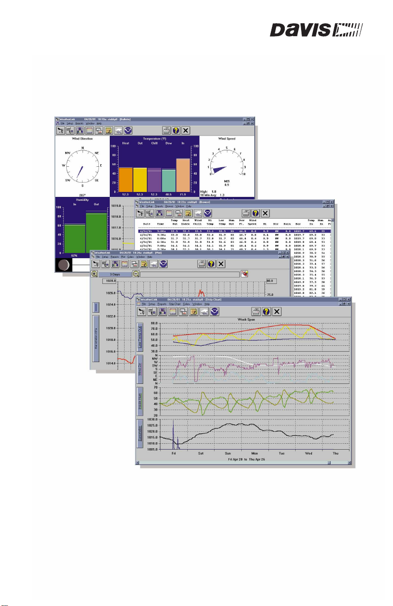
W elcome to Davis Instr uments’ WeatherLink! The data logger and software allow
you to connect your personal computer to Davis weather stations to store, view,
plot, analyze, export, and print weather data collected by your Davis station.
ONTENTS OF PACKAGE
C
Before continuing, please ensure your WeatherLink package contains the following:
▲
Data Logger for Vantage Pro
▲8’
(2.4 m) cable with connector to link your station to your computer.
▲
9-pin (DB-9) PC COM Port Adapter
Use the 9-pin adapter to connect the data logger to a 9-pin serial port. If you
need a 25-pin adapter, contact Davis Instruments technical support at
510.732.7814.
▲
Loopback connector
The loopback connector is a short piece of cable with a phone plug at one end
and a red plastic cap at the other . The loopback connector can be used to deter mine what serial ports are available for the data logger and for troubleshooting communications problems.
I
NTRODUCTION
▲
WeatherLink Software CD ROM
O
PTIONAL ACCESSORIES
The following optional accessories, designed for use with WeatherLink, are available from your dealer or may be ordered directly from Davis.
▲
Telephone Modem Adapter
For transmission of data from the data logger using a modem.
▲
Standard 4-Conductor Extension Cable
For more flexibility in the placement of your console. Add one 40’ (12 m)
extension cable to extend the distance between your station and the computer.
(48’ (14.4 m) maximum)
3
Page 4

H
ARDWARE INSTALLATION
Hardware Requirements
H
ARDWARE INSTALLATION
WeatherLink allows two types of installation: direct connection and phone
modem connection. Direct connection means connecting the computer directly to
the station. Phone modem connection refers specifically to any installation where
the station is connected to a modem and you communicate with the station and
data logger via a modem at your computer. Requirements and installation for
each type of connection differ, and are explained separately below.
H
ARDWARE REQUIREMENTS
The required hardware differs depending on whether you are making a direct
connection or a phone modem connection.
Direct Connection Hardware Requirements
In addition to the provided hardware, the following are required for a direct connection.
▲
Computer running Windows™ 95, 98, 2000, ME or NT 4.0 with at least 5 MB of free
disk space
The amount of space necessary for the data files depends on the archive interval. Database files containing data stored at a 30 minute archive interval
require approximately 36K of disk space per month of data. The file size
changes in a linear fashion depending on the archive interval. For example,
data stored at a 1–minute interval requires approximately 1 MB/month while
the data stored at a 2–hour interval requires approximately 9K/month.
▲
Windows-Compatible Display
VGA minimum. SVGA or High (16-bit) Color recommended.
▲
One Free Serial Port
Phone Modem Connection Hardware Requirements
In addition to the provided hardware and the computer equipment listed above,
the following hardware is required for a phone modem connection.
▲
One external modem to connect to the data logger
The modem must be Hayes
14000 or 19200 baud.
▲
One internal or external modem connected to your computer
The modem must be Hayes®–compatible and run at 1200, 2400, 4800, 9600,
14400 or 19200 baud.
▲
Telephone Modem Adapter
The Telephone Modem Adapter (#6533) provides the connection between the
data logger and the modem.
®
–compatible and run at 1200, 2400, 4800, 9600,
4
Page 5
H
ARDWARE INSTALLATION
Typical Direct Connection
YPICAL DIRECT CONNECTION
T
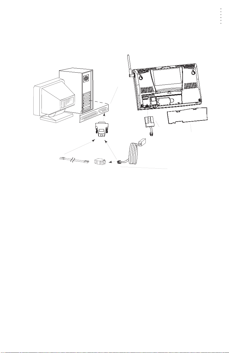
The instructions below explain how to make a typical direct connection. Note that
if you extend the cable run beyond 48' (14.4 m), the software may have difficulty
communicating with the station.
Vantage Pro console
COM Ports
(DB-9)
9-pin connector
data logger
battery cover
8' (2.5 m)
data logger
Optional 40' (12 m) 4-Conductor
Extension Cable and Coupler
YPICAL DIRECT CONNECTION
T
cable
Connection
Options
Direct Connection Installation
1. Enter the console’s Setup Mode by pressing and holding the DONE key, then pressing
the “DOWN arrow” key.
Entering Setup Mode ensures that the station is not writing any data and
saves the current daily totals, highs, and lows to memory.
2. Remove the battery cover from the console back and remove all power by removing
the batteries and AC-power adapter, if present.
Failure to remove power to the console before installing the data logger may
cause damage to the data logger or console.
3. Carefully insert the data logger into the large receptacle jack marked
EXPANSION
inside the battery compartment
Guide the data logger cable through the square slot below the receptacle.
CAUTION:
Make sure that whenever you connect or disconnect the logger from the console that
the console is NOT powered up . Plugging or unplugging the data logger while power
is applied can lock up or damage the logger.
4. Restore power to the weather station by reinstalling the batteries and reattaching the
power adapter, if present.
The weather station should beep three times; each beep should occur within
about one second of the others.
5. Replace the battery cover, ensuring that the data logger cable e xits through the square
slot.
5
Page 6

H
ARDWARE INSTALLATION
Typical Phone Modem Installation
6. Locate a free serial port on the back of your computer and connect the DB9 to the port.
7. Insert the cable plug at the end of the short cable coming from the data logger into the
receptacle on the end of the 8’ cable. Then insert the cable plug on the end of the 8’
cable into the DB9 adapter.
The cable connecting the data logger to the computer is 8’ (2.4 m) long. If you
need to place the station console more than 8’ from the computer, use a 40’ (12
m) standard 4-conductor extension cable. Do not attempt to use more than 40’
of extension cable, or the data logger may have difficulty communicating with
the computer.
Note:
You do not need to keep the console connected to the computer for the logging to work. You
can connect the cable to the computer when you’re ready to download, then disconnect it if
you want to place the console somewhere else. However, you can only run WeatherLink’s bulletin, summary, or real-time strip charts if the console is attached to the computer.
8. Check the Baud rate settings on the console.
Enter the console SETUP mode by pressing and holding the DONE key, then
pressing the DOWN arrow key. Use the BAR and DONE keys to scroll to the
Baud Rate screen. The Baud Rate setting here on the console must be same as
that set in the WeatherLink software. Use the UP and DOWN arrow keys to
change the baud rate setting, if needed. Press and hold DONE to return the
console to current weather mode.
T
YPICAL PHONE MODEM INSTALLATION
The illustration below shows a typical phone modem connection. This involves
connecting the data logger to the weather station and to a modem at the station
console site and connecting your computer’s modem to a phone line, which will
allow you to dial the weather station.
Vantage Pro console
data logger
battery cover
8' (2.5 m)
data logger
cable
T
YPICAL PHONE MODEM INSTALLATION
Note:
Before installing the console and modem at a remote location, test the data logger and connection first using a direct connection like that shown in the section above.
6
Page 7

H
ARDWARE INSTALLATION
Typical Phone Modem Installation
Phone Modem Installation Instructions
1. Install and set up an internal or external modem (according to the instructions supplied
by the manufacturer) for use with your computer.
Make a note of the COM port used by the modem. You will need this information when entering serial port settings for the station.
2. At the station console site, put the external modem in a location where it can connect
to both the logger and a phone jack and plug it into the phone jack. DO NOT TURN THE
MODEM ON AT THIS TIME.
The cable connecting the data logger to the modem is 8’ (2.4 m) long. If you
need to mount the station console more than 8’ from the modem, use a 40’ (12
m) standard 4-conductor extension cable. Do not attempt to use more than 40’
of extension cable, or the data logger may have difficulty communicating with
the modem.
3. Plug the external modem into the phone jack.
4. Place the console in setup mode.
Press and hold the DONE key, then press the DOWN arrow key. Entering
Setup Mode ensures the station is not writing any data to memory and saves
all current highs, lows, and daily totals.
5. Remove the battery cover from the console back and remove all power by removing
the batteries and AC-power adapter, if present.
Failure to remove power to the console before installing the data logger may
cause damage to the data logger or console.
6. Carefully insert the data logger into the large receptacle jack marked
EXPANSION
inside the battery compartment
Guide the data logger cable through the square slot below the data logger
receptacle.
CAUTION:
Make sure that whenever you connect or disconnect the data logger from the con-
sole that the console is NOT powered up. Plugging or unplugging the data logger
while power is applied can damage or lock up the data logger.
7. Connect the Telephone Modem Adapter to the external modem.
Do not use a DB25 (not included) adapter and a gender changer to attach the
logger to a modem because it will not work. Do not use an older Davis telephone modem adapter, either, as it will not work.
8. Insert the cable plug at the end of the cable into the Telephone Modem Adapter.
9. Restore power to the weather station by reinstalling the batteries and reattaching the
power adapter, if present.
The weather station should beep three times; each beep should occur within
about one second of the others.
10. Replace the battery cover, ensuring that the data logger cable e xits through the square
slot.
11. Turn the modem on.
7
Page 8

H
ARDWARE INSTALLATION
Typical Phone Modem Installation
12. Set the Baud rate on the Vantage Pro console.
Enter Setup on the console by pressing and holding the DONE key, then pressing the DOWN arrow key. Use the BAR and DONE keys to scroll through the
setup screens until you reach the BAUD RATE setup screen.
Note:
The Baud Rate setup screen will only appear if you have installed the data logger.
▲
Use the up and down arrows to set the desired Baud rate.
Use the fastest Baud rate your modem can handle. 19200 is the fastest
Baud rate available and is the default setting on the console.
▲
Press DONE when you’ve got the correct Baud rate on the console screen.
Pressing DONE in this screen sends the initialization string to the modem,
so you don’t have to turn the console on and off again.
A Few Notes About Phone Modem Connections
If you indicate a phone modem connection when setting up your station, the software automatically dials the station whenever you initiate a program action that
requires the software to talk to the station.
While connected to a phone modem station, an “On-Line” icon appears in the
toolbar. This icon indicates that you are on-line and may be used to hang up a
remote connection. To hang up, choose the On-Line icon from the toolbar or
choose Hang Up from the File menu.
OOLBAR WITH ON-LINE ICON
T
By default, WeatherLink will hang up the connection to the modem after one
minute without any communication with the station. Use the Serial Port dialog
box in the Setup menu of WeatherLink to change this default value. (See the
WeatherLink help files for more on this subject.)
Note:
WeatherLink will not hang up the phone line if the Bulletin or Summary windows are active.
8
Page 9

S
OFTWARE INSTALLATION AND SETUP
S
OFTWARE INSTALLATION AND SETUP
This chapter covers software installation and setup.
NSTALLING THE SOFTWARE
I
1. Place the Install Disk in your CD ROM drive.
2. The install program should start automatically. If the install program does not start,
choose Run from the Start menu, type D:\SETUP (or E:\SETUP, substituting the correct
drive letter for D or E), and choose OK to begin the installation.
3. Follow the on-screen prompts to complete the installation.
Installing the Software
RUNNING THE SOFTWARE
T o run the softwar e, double-click on the WeatherLink icon. If you have no stations
in the program directory when you run the software, the software will prompt
you to add a station (see below for details). If you have more than one station in
the program directory when you run the software, the software will prompt you
to indicate which station you’d like to open.
STATION SETUP
T o interact with your station, you must add your station to WeatherLink’s database,
which means naming the station, configuring the software to work with that station
and with your computer hardware, and setting station values such as time, barometric pressure, total rainfall, and calibration numbers.
Adding a Station
1. Choose New Station from the File menu.
The software opens the Add New Station dialog box.
2. Type the station name into the text box.
The station name may be up to 40 characters/spaces long. Note that the software uses the first eight characters of the station name (not counting spaces or
punctuation marks) as the name of the directory into which it saves this station’s database and configuration files. The first eight characters of each station name must, therefore, be unique. The software also uses the first three
characters as the file extension for that station’s database files (the first three
characters need not be unique).
3. Choose OK.
The software saves the station, creates a directory and subdirectories for that
station, and prompts you to indicate whether you want to enter the walkthrough procedure.
9
Page 10

SOFTWARE INSTALLATION AND SETUP
Station Setup
About the Walkthrough
The software includes a station setup walkthrough that steps you through the station configuration procedure. After adding a new station, the software automatically asks you whether or not you want to be walked through the configuration
procedure. You can, of course, choose No and set up the station by choosing all of
the necessary commands from the menus. A Walkthrough command is included
in the Setup menu that lets you enter this procedure at any time.
Note:
Where necessary, the software will automatically dial a phone modem station.
If you choose Yes to begin the walkthrough, the software takes you through the
following dialog boxes:
▲ Station Configuration
Set station name, model, accessories, download options, and data file extension.
▲ Serial Port Settings
Set COM port to which data logger is connected. Specify modem connection
settings such as baud rate, phone number, and modem initialization string.
▲ Choose Units
Select units of measure in which station information is displayed.
▲ Set Barometer & Elevation
Set the barometric pressure and your elevation on the station and on the software.
▲ Set Rain Calibration
Set the station’s rainfall calibration number.
▲ Set Temperature and Humidity Calibration
Adjust the temperature and humidity settings on your station if necessary.
▲ Enter Year -to-Date Rainfall
Set the rainfall amount on the station and on the software. You must enter this
information from the software if you want you station and software readings
to agree.
▲ Set Time and Date
Set the time and date on the station, software, and computer and make sure all
three are synchronized.
Note:
When you set the time and date, you will be prompted to clear your archive memory. If
you do not clear archive memory , you may end up with data stor ed at an incorr ect time or
duplicate records. W e recommend that you download before setting the time (unless you
are creating a brand new station) so you may safely clear the archive memory.
▲ Set Archive Interval
Set the interval at which data will be stored in the data logger’s memory. This
will clear any data stored in the data logger.
▲ Set Latitude and Longitude
Y ou must set the corr ect latitude and longitude for the station’s forecast, moon
phase, and sunrise and sunset algorithms to work correctly.
10
Page 11

SOFTWARE INSTALLATION AND SETUP
▲ Set Station Alarms
Set alarm thresholds on the station.
▲ Set Auto Download Time(s)
Specify the stations and the times at which you want data automatically
downloaded to your computer each day.
At each step in the walkthrough procedure, the software will provide confirmation boxes prompting you to indicate whether or not you wish to continue. To
continue, choose OK. To skip any step and move to the next, choose Skip. To cancel the entire walkthrough procedure, choose Cancel.
Finding the Correct Serial Port
FINDING THE CORRECT SERIAL PORT
The software includes a procedure for locating the serial port to which your station is connected or determining whether that serial port is working. Using the
Loopback command (as opposed to Test) will help you find the correct port and
determine whether the serial port or the data logger is causing a communication
problem. The loopback function will also detect and report the presence of any
modems.
To use this procedure, you will need the loopback connector (the short cable with
a phone jack on one end and a red plastic tip on the other) supplied with Weatherlink.
1. If necessary, disconnect the cable between your station
and the adapter connected to the COM port.
2. Insert the loopback connector into the adapter.
3. Choose Serial Port from the Setup menu.
The software opens the Serial Port dialog box.
Loopback
connector
11
Page 12

SOFTWARE INSTALLATION AND SETUP
Finding the Correct Serial Port
4. Choose Loopback.
The software will search all standard serial ports and inform you of the COM
port at which the loopback connector is located.
The software automatically selects the correct COM port for you in the Serial
Port dialog box. If it cannot find the loopback connector at any COM port,
your serial port may not be working. Consult your computer documentation
for help.
12
Page 13

TROUBLESHOOTING GUIDE
TROUBLESHOOTING GUIDE
Communications Problems
The following section answers some of the most commonly asked questions about
W eatherLink.
ing Customer Support (510-732-7814, M-F, 7:00am-5:30pm, Pacific Time). If your
problem is not urgent, send us a description via e-mail (support@davisnet.com)
or fax (510-732-9188). You can also check our web site (www.davisnet.com) for
FAQ’s, troubleshooting information and current copies of all our product documentation.
®
Please consult this guide and the on-line help files before contact-
COMMUNICATIONS PROBLEMS
? Why can't the WeatherLink software communicate with the data logger and station?
If you are having trouble establishing communication between the weather
station and WeatherLink, start by checking the weather station's own diagnostics. Remove all power to the weather station and then restart it by restoring
power (with the data logger still attached).
Note:
The data logger uses non-volatile memory, so you won’t lose any data you’ve already
recorded. However, make sure to put the console in Setup Mode (by pressing and holding
the DONE key, then pressing the DOWN arrow key) before removing the batteries. This
ensures the station will not try to write any data as the power goes off.
▲ You should hear three beeps, each of which occurs when the weather
station passes one of its diagnostic tests. Each beep follows the
previous after about one second. The first beep tells you the processor
is running. The second beep will be for the logger (if installed) and the
third beep is for the display. If you do not hear one or more of these
beeps, contact Davis Instruments at 510-732-7814. (Y ou’ll only hear two
beeps if you don’t have the data logger installed.)
▲ If you hear all three beeps, See “Finding the Correct Serial Port” on
page 11 for instructions on checking your standard serial ports. If this
identifies a serial port other than the one you selected in station setup,
try connecting to the data logger again.
▲ Make sure you are using the blue serial port adapter supplied with
WeatherLink for Vantage Pro. The older, black Davis serial adapters
will not work.
▲ Check the Baud Rate setting on the console and in the serial port dialog
box in the software. Make sure they’re set to the same number.
Note:
Enter the console’s Setup Mode by pr essing and holding the DONE key, then pressing
the DOWN arrow key on the console. Scroll through the setup choices by pressing
the BAR or DONE keys until you reach the Baud Rate screen. This screen only
appears if the data logger is plugged into the console.
If you still cannot connect or if the loopback test identifies the serial port you
already have selected, eliminate the following possibilities. If you have questions on how to proceed, contact your PC vendor or PC technical support.
▲ You have a hardware device conflict.
Check the device manager tab in the Windows® system properties dialog
box to ensure that Windows recognizes your COM port. Consult your pc’s
documentation to see how to access the system properties dialog box.
13
Page 14

TROUBLESHOOTING GUIDE
Program Problems
▲ Your serial port uses a non-standard device name.
WeatherLink recognizes serial ports named COM1 through COM10 only.
To use a modem, you must specify the underlying COM port on your PC.
To find out which port the modem’s connected to, you can look in Windows’ System Properties > Device Manager > “modem name” Properties
> Modem > Port, where “modem name” is the name of the modem you
have installed.
▲ Your serial port is defective.
▲ The loopback connector or the WeatherLink adapter plug is bad.
PROGRAM PROBLEMS
? The barometer graph on the Bulletin does not “fill in” completely.
When you first load the bulletin, the barometer graph will only fill in completely when you have data in your database for the last six hours. Make sure
of the following:
▲ There is data in your database for the span of the barometer graph.
▲ The time and date of the stored barometer data is correct in your database.
▲ The time and date on the PC is correct.
▲ The time and date on the weather station are correct.
? I have duplicate records in my database. Why?
If you do not download from the data logger prior to changing the weather
station’s time and date (for a Daylight Savings time change, for example), you
may get duplicate records. Make sure to download before setting time and
date. In addition, you should be aware that the midnight records are duplicated so they appear in each consecutive day. For example, a midnight record
would appear at the end of the data for November 22 and at the start of the
data for November 23. Using the record editor to change the record in one day
does not change the record in the other day.
Note:
Do not delete the duplicate midnight records; it may affect your rain database or NOAA
monthly summary.
? No wind direction reading (or dashes instead of a reading) appears in my database.
Be aware that if there is no wind speed when the direction is being sampled,
wind direction is not recorded. During intervals with very little wind speed,
no direction may be recorded.
Note:
Since high wind speed is sampled more often, it is possible to have a high wind speed
but no wind speed or direction.
14
Page 15

TROUBLESHOOTING GUIDE
Program Problems
? WeatherLink says “No new data to download” but I know there’s data there. What can
I do?
Vantage is smart enough to send only data it hasn’t already sent to the computer. So, when you initiate a new download, the program will retrieve the
first record after the last record shown in the WeatherLink’s Browse Window.
Older data is stored in the logger as a backup. To see how many of these
backup records are stored in the logger, create a new station and download
the data into this new database. Because there are no records stored in the station you just created, WeatherLink will download everything it has stored.
Next, try clearing the archive memory using the clear dialog box. You will lose
any data not already downloaded in your archive memory, but all of your calibration numbers and alarm settings will remain intact. If this doesn’t work,
reboot your weather station (that is, remove, then restore all power to the station).
Note:
Make sure to put the console in Setup Mode (by pressing the DONE and DOWN arrow
keys) before removing the batteries. The ensur es the station will not try to write any data
when the power goes off.
? After successfully downloading, recent or new data does not appear to be in my data-
base. Where is it?
Check to see if the time and date on your station are incorrect. (This can happen if you have a power outage and your battery backup is dead.) If so, the
data was written into the wrong month, day, and/or time. Reset the time and
date.
It is also possible, if you have multiple stations, that you downloaded data
into the wrong station’s database. Make sure you’ve opened the correct station before downloading.
? When viewing data, dashes appear in place of a value for functions other than wind
direction. Why?
If no data was recorded by a sensor (for example, the sensor was disconnected
or radio interference blocked reception) or if bad data was recorded for a sensor (for example, the sensor was malfunctioning), the software dashes out the
entry rather than showing invalid data. You can use the record editor to correct these entries.
15
Page 16

Open
Station
Bulletin
Window
Plot
Window
TOOLBAR ICONS
Yearly
Rainfall
On-Line
(Hang Up)
View
Help
Download
Strip Chart
Window
Main Program Window
Ctrl-A. . . . . . . Set Alarms
Ctrl-B. . . . . . . View Bulletin
Ctrl-C. . . . . . .Station Configuration
Ctrl-G. . . . . . . Degree-Days Report
Ctrl-H. . . . . . . Hang Up
Ctrl-I . . . . . . .Serial Port Settings
Ctrl-J. . . . . . .Automatic Download
Ctrl-K. . . . . . . Walkthrough
Ctrl-L. . . . . . .Download
Ctrl-O. . . . . . . Open Station
Ctrl-P. . . . . . .Print Active Window
Ctrl-Q. . . . . . . Open Plot Window
Ctrl-R. . . . . . . Yearly Rain Report
Ctrl-S. . . . . . .Open Strip Charts
Ctrl-T. . . . . . .Set Time
Ctrl-U. . . . . . . Select Units
Ctrl-V. . . . . . .View Download Log
Ctrl-W . . . . . .Browse Database
Ctrl-X. . . . . . .Auto Fax Settings
Ctrl-Y. . . . . . .View Summary
Ctrl-Z. . . . . . .Close Window
F1 . . . . . . . . . Context-Sensitive Help
F2 . . . . . . . . . Sunrise/Sunset Report
F7 . . . . . . . . . NOAA This Month
F8 . . . . . . . . . NOAA This Year
Database
Window
This Month s
NOAA Summary
HOT KEYS
Strip Chart Window
Plot Window
Database Window
Yearly Rainfall Window
Print
Window
Exit
Program
ESC . . . . . . . . Halt redraw
Ctrl-M . . . . . . Make Default
Ctrl-P. . . . . . . Print Strip Chart
F1 . . . . . . . . . Context-Sensitive Help
F3 . . . . . . . . . Zoom In
F4 . . . . . . . . . Zoom Out
ESC . . . . . . . . Halt redraw
Ctrl-D . . . . . .Choose Date
Ctrl-M . . . . . . Make Default
Ctrl-P. . . . . . . Print Plot
F1 . . . . . . . . . Context-Sensitive Help
F3 . . . . . . . . . Zoom In
F4 . . . . . . . . . Zoom Out
F9 . . . . . . . . . Overlay Plots
F10 . . . . . . . .Last Year Plot
Ctrl-D . . . . . .Choose Date
Ctrl-N . . . . . . Add Note
Ctrl-P. . . . . . . Print Records
Enter . . . . . . . Edit Record
Delete . . . . . . Delete Record
F1 . . . . . . . . . Context-Sensitive Help
Enter . . . . . . . Edit Year
Delete . . . . . . Delete Year
3465 Diablo Avenue, Hayward, CA 94545-2778
510-732-9229 • Fax: 510-732-9188
E-mail: sales@davisnet.com • http://www.davisnet.com
 Loading...