

Page 1
Vantage Pro
®
Weather Envoy
Installation Manual
Product # 6314 & 631 4C
Page 2

FCC Part 15 Class B Registration Warning
This equipment has been tested and found to comply with the limits for a Class B digital
device, pursuant to Part 15 of the FCC Rules. These limits are designed to provide reasonable protection against harmful interference in a residential installation. This equipment generates, uses, and can radiate radio frequency energy and, if not installed and
used in accordance with the instructions, may cause harmful interference to radio communications.
However, there is no guarantee that interference will not occur in a particular installation.
If this equipment does cause harmful interference to radio or television reception, which
can be determined by turning the equipment on and off, the user is encouraged to try to
correct the interference by one or more of the following measures:
• Reorient or relocate the receiving antenna.
• Increase the separation between the equipment and receiver.
• Connect the equipment into an outlet on a circuit different from that to
which the receiver is connected.
• Consult the dealer or an experienced radio/TV technician for help.
Davis cables must be used for this equipment to comply with the relevant FCC regulations.Changes or modification not expressly approved in writing by Davis Instruments
may void the warranty and user’s authority to operate this equipment.
Product #: 6314 & 6314C
Part Number: 7395.181
Weather Envoy Installation Manual
Rev A Manual (September 26, 2002)
This product complies with the essential protection requirements of the EC EMC Directive 89/
336/EC..
(c) Davis Instruments Corp. 2002. All Rights Reserved.
3465 Diablo Avenue, Hayward, CA 94545-2778 U.S.A.
510-732-9229 • Fax: 510-732-9188
E-mail: info@davisnet.com • www.davisnet.com
Page 3

Table of Contents
Table of Contents
Welcome to the Weather Envoy! . . . . . . . . . . . . . . . . . . .1
Contents . . . . . . . . . . . . . . . . . . . . . . . . . . . . . . . . . . . . . . . . . . . . . . . .1
Required for Operation . . . . . . . . . . . . . . . . . . . . . . . . . . . . . . .1
All Weather Envoys: . . . . . . . . . . . . . . . . . . . . . . . . . . . . . . .1
Wireless Weather Envoy: . . . . . . . . . . . . . . . . . . . . . . . . . . .1
Cabled Weather Envoy: . . . . . . . . . . . . . . . . . . . . . . . . . . . .1
Optional Accessories . . . . . . . . . . . . . . . . . . . . . . . . . . . . . .2
Hardware Installation . . . . . . . . . . . . . . . . . . . . . . . . . . . .2
Hardware Requirements . . . . . . . . . . . . . . . . . . . . . . . . . . . . . . . . . . . .2
Local Connection Windows Computer Requirements . . . . . . . .2
Local Connection Macintosh Computer Requirements . . . . . . .2
Preparing the Envoy . . . . . . . . . . . . . . . . . . . . . . . . . . . . . . . . . . . . . . .3
Installing the Data Logger . . . . . . . . . . . . . . . . . . . . . . . . . . . . .3
Installing the Batteries . . . . . . . . . . . . . . . . . . . . . . . . . . . . . . . .4
Connecting AC Power . . . . . . . . . . . . . . . . . . . . . . . . . . . . . . . .5
Connecting a Cabled Envoy to the Integrated Sensor Suite (ISS) 5
Mounting the Envoy . . . . . . . . . . . . . . . . . . . . . . . . . . . . . . . . . .6
Local Computer Installation . . . . . . . . . . . . . . . . . . . . . . . . . . . . . . . . . .7
Installing with a Local Computer . . . . . . . . . . . . . . . . . . . . . . . .7
Remote Computer Installation . . . . . . . . . . . . . . . . . . . . . . . . . . . . . . . .8
Remote Modem Connection Hardware Requirements . . . . . . .8
Installing with a Remote Computer . . . . . . . . . . . . . . . . . . . . . .9
A Few Notes About Phone Modem Connections . . . . . . . . . . . .9
Software Installation and Setup . . . . . . . . . . . . . . . . . . .10
Installing the Software . . . . . . . . . . . . . . . . . . . . . . . . . . . . . . . . . . . . . .10
Windows Computer . . . . . . . . . . . . . . . . . . . . . . . . . . . . . . . . . .10
Macintosh Computer . . . . . . . . . . . . . . . . . . . . . . . . . . . . . . . . .10
Running the Software . . . . . . . . . . . . . . . . . . . . . . . . . . . . . . . . . . . . . .10
Station Setup . . . . . . . . . . . . . . . . . . . . . . . . . . . . . . . . . . . . . . . . . . . . .10
Adding a Station . . . . . . . . . . . . . . . . . . . . . . . . . . . . . . . . . . . .10
About the Walkthrough . . . . . . . . . . . . . . . . . . . . . . . . . . . . . . .11
New Station . . . . . . . . . . . . . . . . . . . . . . . . . . . . . . . . . . . . . . . .12
Station Configuration . . . . . . . . . . . . . . . . . . . . . . . . . . . . . . . . .13
Serial Port . . . . . . . . . . . . . . . . . . . . . . . . . . . . . . . . . . . . . . . . .14
Configure Console . . . . . . . . . . . . . . . . . . . . . . . . . . . . . . . . . . .15
Select Units . . . . . . . . . . . . . . . . . . . . . . . . . . . . . . . . . . . . . . . .16
Set Barometer . . . . . . . . . . . . . . . . . . . . . . . . . . . . . . . . . . . . . .17
i
Page 4

Table of Contents
Set Rain Cal . . . . . . . . . . . . . . . . . . . . . . . . . . . . . . . . . . . . . . .18
Set Temp & Hum Cal . . . . . . . . . . . . . . . . . . . . . . . . . . . . . . . . .18
Set Total Rain . . . . . . . . . . . . . . . . . . . . . . . . . . . . . . . . . . . . . . 19
Set Time . . . . . . . . . . . . . . . . . . . . . . . . . . . . . . . . . . . . . . . . . . 19
Set Archive Interval . . . . . . . . . . . . . . . . . . . . . . . . . . . . . . . . . .20
Set Latitude and Longitude . . . . . . . . . . . . . . . . . . . . . . . . . . . .20
Set Alarms . . . . . . . . . . . . . . . . . . . . . . . . . . . . . . . . . . . . . . . . .22
Auto Download . . . . . . . . . . . . . . . . . . . . . . . . . . . . . . . . . . . . .23
Alarms . . . . . . . . . . . . . . . . . . . . . . . . . . . . . . . . . . . . . . . 24
Three special alarms . . . . . . . . . . . . . . . . . . . . . . . . . . . . . . . . . . . . . . .25
Weather Data Measured & Calculated . . . . . . . . . . . . . . 25
Wind . . . . . . . . . . . . . . . . . . . . . . . . . . . . . . . . . . . . . . . . . . . . . . . . . . . 25
Temperature . . . . . . . . . . . . . . . . . . . . . . . . . . . . . . . . . . . . . . . . . . . . .25
Apparent Temperatures . . . . . . . . . . . . . . . . . . . . . . . . . . . . . . . . . . . .25
Humidity . . . . . . . . . . . . . . . . . . . . . . . . . . . . . . . . . . . . . . . . . . . . . . . .26
Dew-Point . . . . . . . . . . . . . . . . . . . . . . . . . . . . . . . . . . . . . . . . . . . . . . .27
Rainfall . . . . . . . . . . . . . . . . . . . . . . . . . . . . . . . . . . . . . . . . . . . . . . . . .27
Barometric Pressure . . . . . . . . . . . . . . . . . . . . . . . . . . . . . . . . . . . . . . .27
Solar Radiation . . . . . . . . . . . . . . . . . . . . . . . . . . . . . . . . . . . . . . . . . . .28
UV (Ultra Violet) Radiation . . . . . . . . . . . . . . . . . . . . . . . . . . . . . . . . . .28
EvapoTranspiration (ET) . . . . . . . . . . . . . . . . . . . . . . . . . . . . . . . . . . . .31
Leaf Wetness . . . . . . . . . . . . . . . . . . . . . . . . . . . . . . . . . . . . . . . . . . . .31
Soil Moisture . . . . . . . . . . . . . . . . . . . . . . . . . . . . . . . . . . . . . . . . . . . . . 31
Time . . . . . . . . . . . . . . . . . . . . . . . . . . . . . . . . . . . . . . . . . . . . . . . . . . .31
Troubleshooting Guide . . . . . . . . . . . . . . . . . . . . . . . . . . 32
Communications Problems . . . . . . . . . . . . . . . . . . . . . . . . . . . . . . . . . . 32
Finding the Correct Serial Port . . . . . . . . . . . . . . . . . . . . . . . . . . . . . . .33
Modem Initialization String . . . . . . . . . . . . . . . . . . . . . . . . . . . . . . . . . . 34
Program Problems . . . . . . . . . . . . . . . . . . . . . . . . . . . . . . . . . . . . . . . . 34
Contacting Davis Technical Support . . . . . . . . . . . . . . . . . . . . . . . . . . .35
Specifications . . . . . . . . . . . . . . . . . . . . . . . . . . . . . . . . . . . . . . . . . . . .36
ii
Page 5
WELCOME TO TH E WEATHER ENVOY!
Contents
Welcome to the Weather Envoy!
Welcome to Davis Instruments’ Weather Envoy! The We at he r Env oy pr ov ides a
new and exciting way of getti ng your Davis weather station data into your
Windows (95 or later) or Macintosh (OS X) computer.
The Weather Envoy includes the data collection and logging functions of the Vantage Pro console, but in a smaller package that can be discreetly placed next to
your computer. Both cabled and wireless versions of the Weather Envoy ar e av a ilable. In combination with our WeatherLink software, the Weather Envoy allows
you to view, store, plot, analyze, export, share and print your weather data.
Contents
Before continuing, please be sure your Weather Envoy package includes the
following:
▲ Envoy console
▲ Two #6 x 1” screws for wal l mo unting
▲ AC-power adapter
Required for Operation
In order to use your Weather Envoy, you will also need the following Davis
weather products:
All Weather Env oys:
▲ WeatherLink for V anta ge Pr o (Windows version 5.2 or later (#6510C), Mac OS
X version 5.01 or later (#6520C))
Wireless Weather Envoy:
▲ Wireless Integrated Sensor Suite (ISS) or ISS Plus
or
▲ Wireless Vantage Pro (Plus) Weather Station
Cabled Weather Envoy:
▲ Cabled ISS or Cabled ISS Plus
1
Page 6

HARDWARE INSTALLATION
Optional Accessories
Optional Accessories
The following optional accessories are designed for use with your Envoy. They
are available from your dealer or may be ordered directly from Davis.
▲ Telephone Modem Adapter (#6533)
Allows transmission of data from the data logger using a modem.
▲ Standard 4-Conductor 40’ Extension Cable (#7876-040)
For more flexibility in the placement of your Weather Envoy, add one 40’
(12 m) extension cable to extend the distance bet ween your station and the
computer. (48’ (14.4 m) maximum)
Hardware Installation
The Weather Envoy allows two types of installation: local connection to a
computer and remote connection to a computer via a modem. Requirements and
installation for each type of connection differ, and are explained separate ly below.
Hardware Requirements
Note: The amount of storage space necessary for the data files depends on the archive
interval. Each archive record in the database is 88 bytes. Every day in the database
has an additional two records totalling 176 bytes that store daily summary information. A database containing data stored at a 30-minute archive interval requires
approximately 4400 bytes of disk space per day or 132KB of disk space per month.
The disk space requirements change in a linear fashion depending on the archive
interval. For example, data stored at a one-minute interval requires approximately 3.8
MB a month while data stored at a two-hour interval requires approximately 32 KB a
month.
Local Connection Windows Computer Requirements
Your Weather Envoy requires the following for a local Windows computer
connection:
▲ Computer running Windows™ 95, 98, 2000, XP, ME, or NT 4.0 with at least 5
MB of free disk space
▲ Windows-compatible display
VGA minimum. SVGA or High (16-bit) Color or better recommended.
▲ One free serial port
Local Connection Macintosh Computer Requirem ents
Your Weather Envoy requires the following for a local Macintosh computer
connection:
▲ Macintosh computer running Mac OS X v10.01 or newer with at least 5 MB of
free disk space
▲ A USB to serial port co nverter connected to a Macintosh USB port.
2
Page 7
HARDWARE INSTALLATION
Preparing the Envoy
Preparing the Envoy
Perform the following procedures to prepare your Envoy for operation.
▲ Install the Data Logger
▲ Install the Batteries
▲ Mount your Envoy
▲ Make the Envoy Connections
▲ Test using WeatherLink
▲ Setup the Envoy using WeatherLink
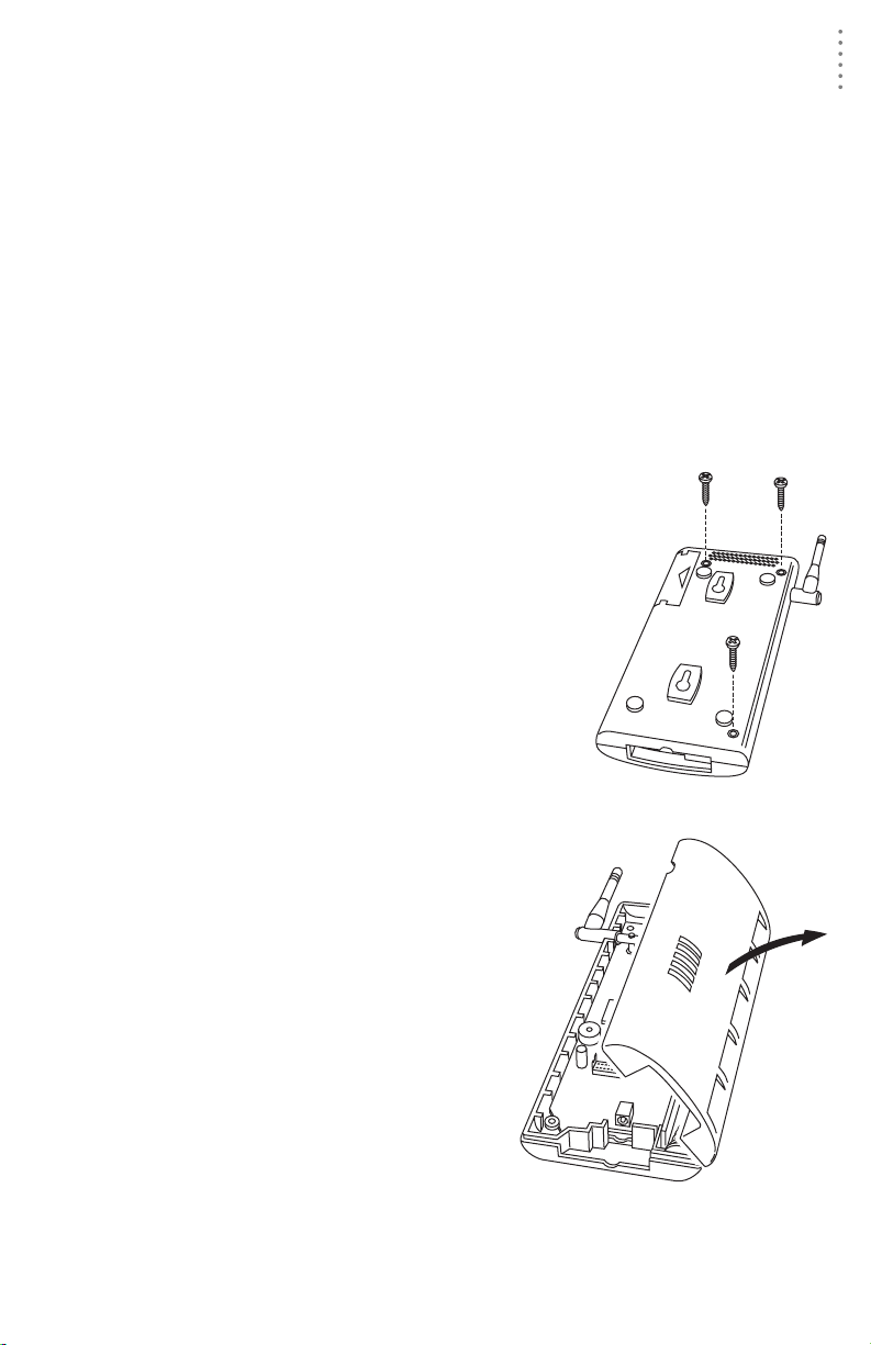
Installing the Data Logger
CAUTION: The We athe rLink data logger must be installed before you install the
1. Remove the three screws from the back of the
batteries!
Envoy case.
2. Separate the case halves to expose
the data logger connector.
3
Page 8
HARDWARE INSTALLATION
Preparing the Envoy
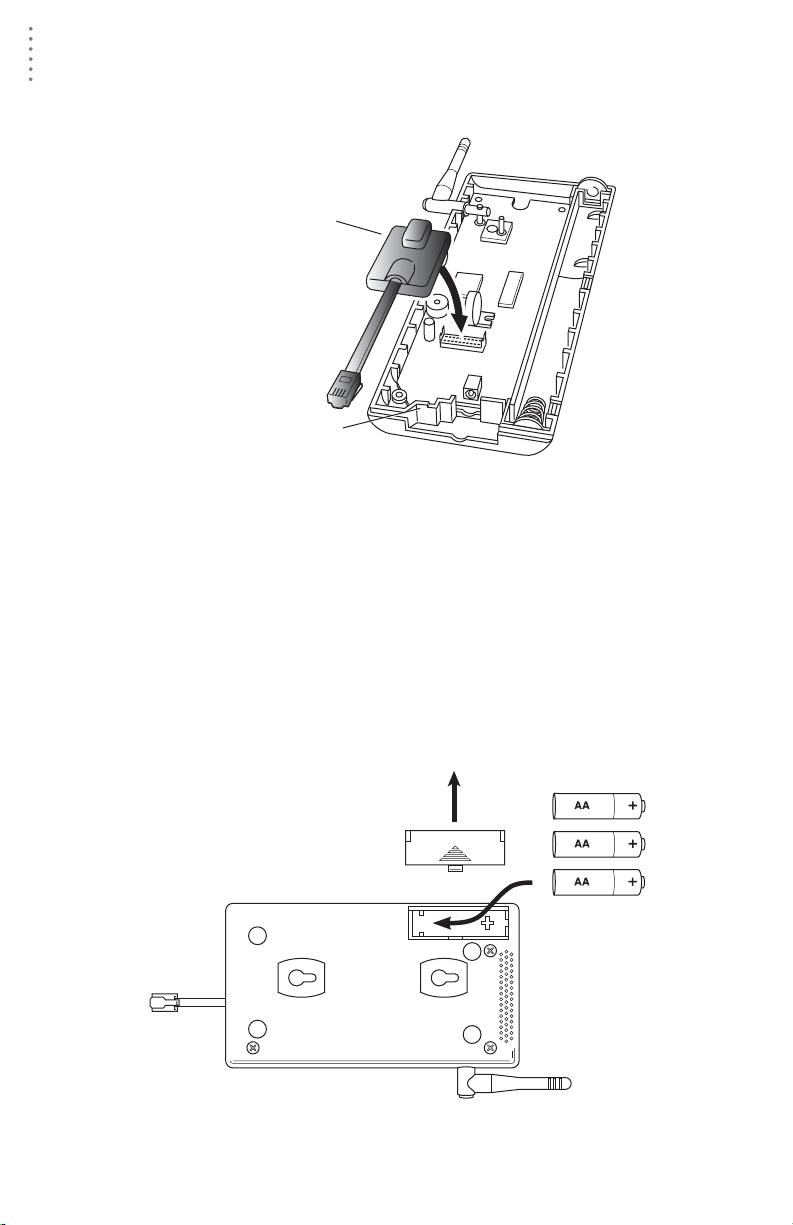
3. Carefully insert the data logger into the connector.
Note:Be sure to push down firmly on the data logger to seat the connection.
Data Logger
Data Logger Cable Channel
Installing the Data Logger
4. Rejoin the case halves, making sure the da ta logger cable passes through the
cable channel.
5. Fasten using the three screws you previously removed.
Installing the Batteries
CAUTION: The We athe rLink Data Logger must be installed before you install the
backup batteries!
1. Find the battery cover on the back side of the Envoy case.
2. Remove the battery cover by pressing on the arrow embossed on the cover
and sliding the cover away from the case.
Installing the Batteries
4
Page 9
HARDWARE INSTALLATION
Preparing the Envoy
3. Insert the three AA-cell batteries, negative terminal (flat side) first.
The Envoy will run through a brief self-test procedure. If the test is successful
you will hear two (2 ) beeps.
4. Replace the battery cover on the case.
Note: Operating on battery power alone, the Cabled Weather Envoy will run approximately
10 days and the Wireless Weather Envoy will run approximately 5 months.
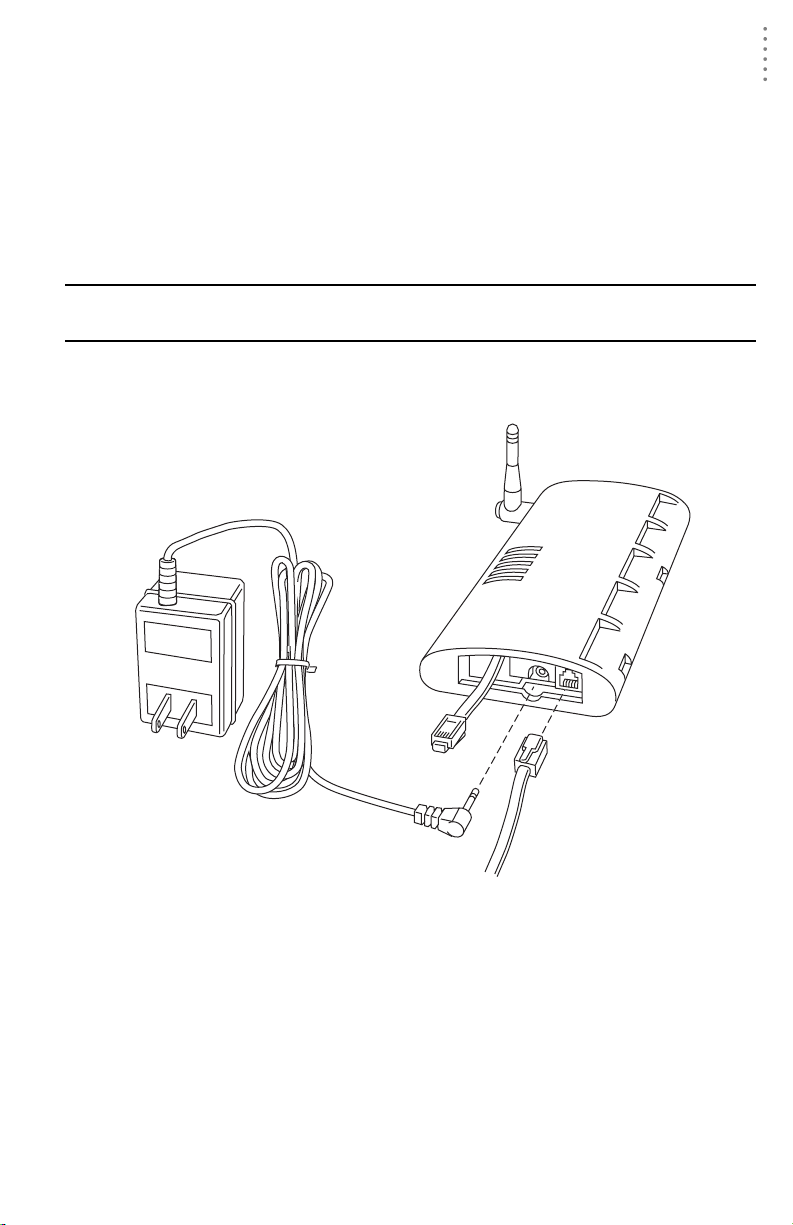
Connecting AC Power
CAUTION: The We athe rLink Data Logger and the backup batteries must be
installed before you connect AC power!
1. Locate the power adapter jack on the end of the Envoy case. It’s next to the
data logger output cable.
Envoy
Data Logger
AC Power
Adapter
Power, Sensor, and Computer Connections
To
Computer
Power
Jack
From Integrated
Sensor Suite
(cabled models only)
2. Insert the power adapter plug into the power jack.
Connecting a Cabled Envoy to the Integrated Sensor Suite (ISS)
Refer to the figure shown in above “Connecting AC Power”.
1. Insert the modular plug into the ISS jack on the En voy case.
You wo n’t be able to test the co nnection between th e Envoy and the ISS until
you have finished installing the WeatherLink software.
5
Page 10
HARDWARE INSTALLATION
Preparing the Envoy
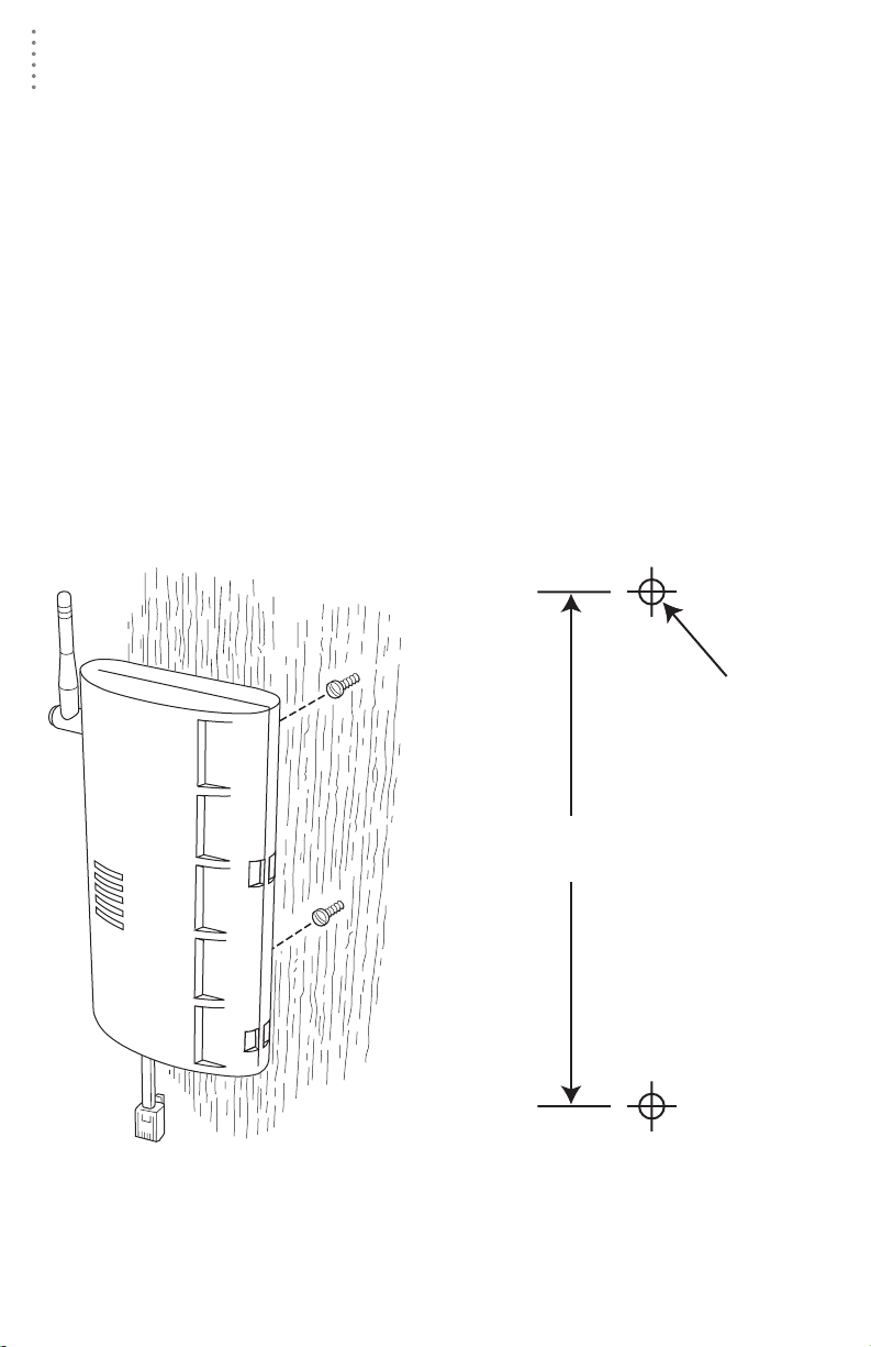
Mounting the Envoy
Yo u can install your Envoy on your desktop or on the wall next to your computer.
Note: Whenever you first install the Weather Envoy, place the antenna in a vertical position.
If necessary, you can adjust the angle for best reception after it’s installed.
Use this procedure for a wall installation.
1. Find the template located on the next page.
2. Hold the template against the wall where you want to mount the Envoy, an d
use a pencil to mark the location for the two mounting screws.
The screws should be 3.25” (82.5mm) apart and lined up vertically.
3. Drill the marked locations with a 3/32” or 7/64” ( 2.2 to 2.7 mm) drill bit.
4. Drive the two #6 x 1” (~ 3.5mm x 25mm) pan head self-threading screws into
the wall.
Leave at least a 1/8” (~ 3mm) space between the wall and the heads of the
screws.
5. Slide the keyholes on the back of the case over the two screw heads.
#6 x 1"
Pan-Head
Screws
(~2.2 to 2.7mm)
Drill 3/32"
or 7/64"
Holes
3.25"
(82.55mm)
Wall Mounting the Weather Envoy
Wall Mounting Template
6
Page 11
HARDWARE INSTALLATION
Local Computer Installation
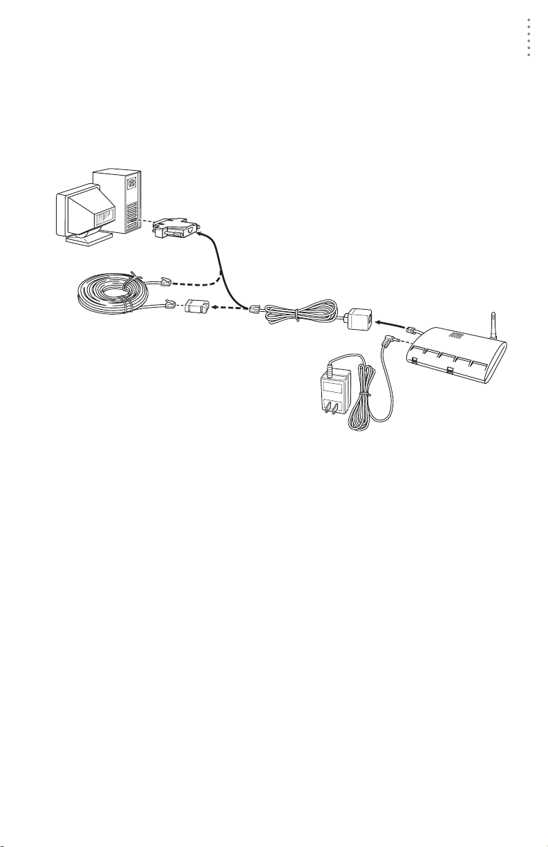
Local Computer Installation
The instructions below explain how to make a typical local connection. Note that
if you extend the cable run beyond 48’ (14.4 m), the software may have difficulty
communicating with the station.
Note: Mac Users - Refer to your WeatherLink for Mac OS X Getting Started Guide for addi-
tional installation instructions.
9-Pin
Connector
(DB-9)
Weather Envoy
Optional 40' (12 m) 4-Conductor
Extension Cable and Coupler
8' (2.5 m) Cable
Data Logger
AC Power
Adapter
Local Computer Installation
Installing with a Lo cal Comput er
1. Locate a free serial port on the back of your computer and connect the DB9 to
the port.
2. Insert the cable plug at the end of the short cable coming fr om th e data logger
into the receptacle on the end of the 8’ cable. Then insert the cable plug on the
end of the 8’ cable into the DB9 adapter.
The cable connecting the data logger to the computer is 8’ (2.4 m) long. If you
need to place the station console more than 8’ from the computer , us e a 4 0’ (12
m) standard 4-conductor extension cable (# 7876-040). Do not attempt to use
more than 40’ of exten sion cable, or the data logger may ha ve difficulty communicating with the computer.
Note: The Weather Envoy data logger does not need to be connected to the computer for
the logging to work. You can connect the cable to the computer when you’re ready to
download, then disconnect it if you want to place the Weather Envoy somewhere
else. However, the WeatherLink bulletin, summary, or real-time strip charts can be
displayed only while the Weather Envoy is attached to the computer.
7
Page 12
HARDWARE INSTALLATION
Remote Computer Installation
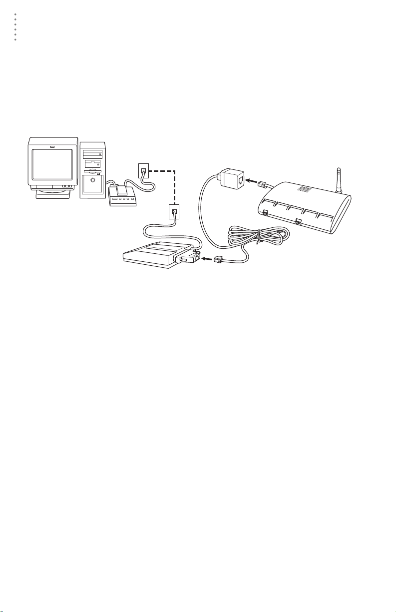
Remote Computer Installation
The illustration below shows a typical remote computer installation using a
modem. This involves connecting the data logger to the Weather Envoy and to a
modem at the station console site and connecting your computer’s modem to a
phone line, which will allow you to dial the Weather Envoy .
Note: Mac Users - Refer to your WeatherLink for Mac OS X Getting Started Guide for addi-
tional installation instructions
Weather Envoy
with Data Logger
Windows Computer
Note: Before installing the console and modem at a remote location, test the data logger
and connection first using a direct connection like that shown in the section above.
External or
Internal Modem
External
Modem
25-pin Telephone Modem
Remote Computer Installation
8 feet (2.5 m)
Data Logger Cable
(standard)
Adapter (#6533)
Remote Modem Connection Hardware Requirements
The following additio nal hardware is requ ired for a phone modem conne ction.
▲ One internal or external modem connected to your computer
The modem must be Hayes®–compatible and run at 1200, 2400, 4800, 9600,
14400 or 19200 baud.
▲ One external modem to connect to th e Weather Envoy data logger
The modem must be Hayes
14000 or 19200 baud.
▲ Telephone Modem Adapter
The Telephone Modem Adapter (#6533) provides the connection between the
Weather Envoy data logger and the modem.
®
–compatible and run at 1200, 2400, 4800, 9600,
8
Page 13

HARDWARE INSTALLATION
Remote Computer Installation
Installing with a Remote Computer
1. Install a nd se t up an intern al or ex terna l modem (ac cor din g to th e instr uctio ns
supplied by the manufacturer) for use with your computer.
Make a note of the COM port used by the modem. You will need this informa-
tion when entering serial port settings for the station.
2. At the Weather Envoy site, put the exte rnal modem in a locatio n where it can
connect to both the data logger and the phone jack.
Note: Both the modem and the Weather Envoy should be powered down at this time, if they
are not already turned off.
The cable connecting the data logger to the modem is 8’ (2.4 m) long. If you
need to mount the station console more than 8’ from the modem, use a 40’ (12
m) standard 4-conductor extension cable. Do not attempt to use more than 40’
of extension cable, or the data logger may have difficulty communicating with
the modem.
3. Plug the external modem into the phone jack.
4. Conn ec t th e Weather Envoy data logge r to the modem.
5. Power up the modem.
6. Power up the Weather Envoy last.
A Few Notes About Phone Modem Connections
If you indicate a phone modem connection when setting up your station, the
software automatically dials the station whenever you initiate a program ac tion
that requires the software to talk to the station .
While connecte d to a phone modem station, an “On- Line” icon appears in the
toolbar. This icon indicates that you are on-line and may be used to hang up a
remote connection. To hang up, click on the On-Line icon from the toolbar or
choose Hang Up from the File menu.
On-Line Icon
Toolbar with On-Line Icon
By default, WeatherLink will hang up the connection to the mode m after one
minute without any communica t ion wit h th e station . Use th e Seria l Por t dialog
box in the Setup menu of WeatherLink to change this default value. (See the
WeatherLink help files for more on this subject.)
Note: WeatherLink will not hang up the phone line if the Bulletin or Summary windows are
active.
9
Page 14

SOFTWARE INSTALLATION AND SETUP
Installing the Software
Software Installation and Setup
Refer to the following procedure to install WeatherLink software on your
computer.
Installing the Software
Windows Computer
1. Place the Install Disk in you r CD ROM drive.
2. The insta ll pr og ra m sh oul d st ar t au t om atic all y. If the inst all pr ogram does not
start, choose Run from the St art menu, type D:\SETUP ( or E:\SETUP, substituting the correct drive letter for D or E), and choose OK to begin the installation.
3. Follow the on-screen prompts to complete the installation.
Macintosh Computer
1. Place the Install Disk in you r CD ROM drive.
2. Copy “install.sit” from the CD to your destop and open it.
The installation software will automatically extract itself.
3. Run “in st all ”.
4. Follow the on-screen prompts to complete the installation.
Running the Software
T o r un the s oftwa re, double-c lick on the WeatherLink icon. If you h ave no st ation s
in the program directory when you run the software, the software will prompt
you to add a station (see below for details). If you have more than one station in
the program directory when you run the software, the software will open the last
station access ed.
Station Setup
T o interact with your station, you must add your station to W eathe rLink’s database,
which means naming the station, configuring the softwar e to wo rk with that st ation
and with your computer hardwar e, and set ting sta tion values such a s time ,
barometric pressur e, tota l rainfall, a nd calibrat ion numbers.
Adding a Station
1. Choose New Station from the File menu.
The software opens the Add New Station dialog box.
2. Type the station name into the text box.
The station name may be up to 40 characters/spaces long. Note that the software uses the first eight characters of the station name (not counting spaces or
punctuation marks) as the name of the directory into which it saves this station’s database and configuration files. The first eight characters of each station name must, therefore, be unique.
10
Page 15

SOFTWARE INSTALLATION AND SETUP
Station Setup
3. Choose OK.
The software saves the station, creates a directory and subdirec tories for that
station, and prompts you to indicate whether you want to enter the walkthrough procedure.
About the Walkthrough
The software incl udes a “Walkthrough ” u tilit y t ha t ste p s you t hrough most of the
station setup and configuration procedures. After adding a new station, the software automatically asks you whether or not you want to be walked through the
configuration procedure. You can, of course, choose No and set up the station by
choosing all of the necessary commands from the menus. A Walkthrough command is included in the Setup menu that lets you begin this procedure at any
time.
Note: If you have a remote computer connection, then the software will automatically dial a
phone modem station when it is necessary.
Note: Mac Users - Your Walkthrough will be a little different. Please refer to your Weather-
Link for Mac OS X Getting Started Guide for Walkt hrough infor mation.
If you choose Yes to begin th e Walkthrough, the software takes you through the
following dialog boxes:
▲
Station Conf iguration
Set station name, model, accessories, download options, and data file
extension.
Serial Port Settings
▲
Set COM port to which data logger is connected. Specify modem connection settings such as baud rate, phone number, and modem initialization
string.
Configure C onsole
▲
Use the Configure Console dia log box to set the DavisTalk transmitter ID
assignments, turn on an d off the console retransmit function, set daylight
savings time, select start of the rain season, and enable or disable averaging of temperatures over the archive period.
▲ Choose Units
Select units of measure in which station information is displayed.
▲
Set Barometer & Elevation
Set the barometric pressure and your elevation on the station and on the
software.
▲
Set Rain Calibration
Set the station’s rainfall calibration number.
▲
Set Temperature and Humidity Calibration
Adjust the temperat ure and humidity settings on your st ation if necessary.
▲
Enter Year-to-Date Rainfall
Set the rainfall amount on the station and on the software. You must enter
this information from the software if you want you station and software
readings to agree.
Set Time and Date
▲
Set the time and date on the station, software, and computer and make
sure all three are synchronized.
11
Page 16

SOFTWARE INSTALLATION AND SETUP
Station Setup
Note:When you set the time and date, you will be prompted to clear your archive memory.
If you do not clear archive me m ory, you may end up with data stored at an incor rect
time or duplicate records. We recommend that you download before setting the time,
unless you are creating a brand new station or just adjusting the time, so you may
safely clear the archive memory.
▲ Set Archive Interval
Set the interval at which data will be stored in the data logger’s memory.
This will clear any data stored in the data logger.
▲
Set Latitude and Longitude
You must set the correct latitude and longitude for the station’s forecast,
moon phase, and sunrise and sunset algorithms to work correctly.
▲
Set Station Alarms
Set alarm thresholds on the station.
▲
Set Auto Download Time(s)
Specify the stations and the times at which you want data automatically
downloaded to your computer each day.
At each step in the Walkthrough procedure, the software will provide confirmation boxes prompting you to indicate whether or not you wish to continue. To
continue, choose OK. To skip any step and move to the next, choose Skip. To cancel the entire Walkthrough procedure, choose Cancel.
New Station
Each station connected to the compute r must have its own “station” within the
software. This tells the software into which database new data should be saved,
provides the necessary communication settings (serial port, etc.), and other
station-specific information.
1. Choose New Station from the File menu.
The New Station dialog box appears.
New Station
2. To add a station, type the desired station name (up to 40 characters/spaces)
into the Station Name text box and choose OK.
The software saves the station, creates a directory for that station using the
first eight characters in the station name (not including punc tuation and
spaces), and pro m pts you to indicate whet her yo u wan t to enter the Walkthrough procedure (see “About the Walkthrough” on page 11).
12
Page 17

SOFTWARE INSTALLATION AND SETUP
Station Configuration
You may enter information which will help to identify a particular stat ion and
select a number of station-specific settings.
1. Choose Station Config from the Setup menu or press Ctrl-C.
The Station Configuration dialog box appears.
Station Setup
Station Configuration
2. Enter the following information:
▲
Name
Enter the desired station name in this text box. Note that when you first
create a station, the s oftware uses the first eight characters of the station
name as the name of the directory into which it saves th is station’s database and configuration files. If you ch ange the station name, the software
will prompt you to change the name of the station directory.
Model
▲
Select the weather station model from the drop-down list. Select “Vantage
Pro” or “Vantage Pro Plus” if the list does not include “Envoy”.
▲ Rain Collector
Select the increment in which the rain collector you use with the station
measures rainfall. If you do not have a rain collector, choose None.
▲
Optional Accessories
Check each of the listed optional sensors that ar e ins talled in your weather
station.
▲ Download Options
The software can automatically create a space-delimited text file containing two-days worth of data records after each download. To enable this
feature, check the box. The file is named “dow nloa d.t xt” an d is save d into
the station directory.
13
Page 18

SOFTWARE INSTALLATION AND SETUP
Station Setup
Note: The “download.txt” file is written as a space-delimited file. The export feature avail-
able in the Browse Window produces a tab-delimited file.
3. When finished, choose OK.
The software saves the station configuration settings.
Serial Port
To commun ic ate with the data logger and station you must select the serial port
you are using and enter the correct settings.
1. Choose Serial Port
from the Setup
menu or press CtrlI.
The Serial Port Settings dialog box
appears.
2. Enter the following
information:
▲
Serial Port
Select the serial
port to which
the data logger
or modem is
connected.
Baud Rate
▲
Serial Port
Set the baud
rate to 19200, th e d efault baud rate fo r the Weather Envoy Dat a Logger.
▲ Hangup Wait Ti m e
Enter the amount of time, in minutes, the program should wait before
hanging up the connection and re leasin g the seri al port durin g an idle c onnection. If, for example, you’v e dialed your s tation, do wnl oaded da ta, and
then left the connection open without the bulleting or summary running,
the software will ha ng up th e mo dem aft er t he t im e you specify here. This
feature is useful if another program uses the modem or another program
accesses the data logger.
Dial Up Connection
▲
Select this check box to connect to the Weather Envoy by modem (remote
connection). Once you’ve selected this box, the grayed-out options in the
lower part of the dialog box will be activated.
Weather Station Phone Number
▲
Enter the phone number for th e modem connected to the station (Weather
Envoy) in this box. Make sure to enter the area code and any necessary
prefixes (for example, 1, 011, etc.).
▲ Enter a comma (,) to force the modem to pause before dialing the next
digit. You may enter more than one comma to inc rease the length of
time for which the modem pauses.
▲ Enter a “w” to force the modem to wait for a dial tone before dialing
the next digit.
14
Page 19

SOFTWARE INSTALLATION AND SETUP
▲ Modem Initialization String
The default modem initialization string should work in almost all cases:
AT &F S7=60 E Q V X4. Before changing the modem string, see “Modem
Initialization String ” on page34 for an explana tion of wh at each part of the
string means.
▲ After Connect Wait
Controls the number of seconds the software waits after it has connected
to a remote station before sending the first command. If you are having
difficulty connecting to a remote statio, try increasing the wait time.
▲
Rotary Dial
Select this check box if you are have a remote connec tion to the station by
modem using a phone modem connection and your phone is rotary dial.
3. When finish ed selecting options, choose Test.
The software will check the connection to the station (or modem) using the
current settings and indicate whether or not it successfully connected to your
Weather Envoy. If you cannot connect to the station, you may use Loopback
(see “Finding the Correct Serial Port” on page 33) to determine the correct
serial port or make sure the serial port itself is actually working.
4. Once the serial port settings are correct, choose OK.
The software saves the serial port settings.
Configure Console
Use the Configure Console
dialog box to set the DavisTalk transmitter ID assignments, turn on and off the
Weather Envoy retransmit
function, set daylight savings time, select start of the
rain season, and enable or
disable averaging of temperatures over the archive
period.
1. Choose Configure Console
from the Setup menu.
The Serial Port Settings dialog box appears.
2. Set the Station Types
Select the station type used
by each of the DavisTalk
transmitter IDs.
Cabled Weather Envoys
▲
must have Station No. 1
set to ISS.
▲ If you are using a Temp/
Hum station and no IS S,
select Temp/Hum (ISS).
▲ You can select CLEAR ALL to set all transmitters to Off.
Configure Console
Station Setup
15
Page 20

SOFTWARE INSTALLATION AND SETUP
Station Setup
3. Set Retransmit
If you want your Weather Envoy to retransmit weather data, say to either a
Vantage Pro console or a Weather Echo, turn Retransmit ON by selecting the
transmitter ID number for the retransmitted signal.
4. Set Daylight Savings
Select your local time zone from the list.
Y ou c an manuall y turn on Da ylight Sav ings by se lecting On. If you select Auto
Detect Daylight Savings, dayl igh t sav in gs time will automatically turn on at
1 am on the first Sunday in April and turn off at 2 am on the last Sunday in
October, or will turn off the last Sunday in March in Europe and Australia. If
neither On or Auto Detect Daylight Savings are selected, Daylight savings is
set to off.
5. Set Rain Season Start
Enter the date on which to start the annual rain totals. The rain season will
start on the first day of the month you select.
6. Set Average Temp Over Archive Period
The defalt is to log the temperature at the end of the archive period.
7. When finish ed configuring the console, choose Set.
The software sets the alarms on the station console to match the settings in this
dialog box.
Select Units
You may select the units of measure in which data is displayed within the
software. All program windows (bulletin, summary, plots, database, etc.) display
data in the selected units of measure.
1. Choose Select Units from the Setup menu or press Ctrl-U.
The Choose Units dialog box appears.
2. Select the desired units of measure:
▲
Temperature: Fahrenheit (°F) or Celsius
(°C)
Wind chill, dew point, degree-days,
and heat index are all displ ay ed in th e
same unit of measure as temperature.
Barometer: Inches of Hg (in),
▲
Millimeters of Hg (mm), Millibars (mb),
or Hectopascals (hPa)
▲ Wind Speed: Miles per Hour (mph),
Knots (knot), Kilometers per Hour (km/
hr), or Meters per Second (m/s)
▲ Rain: Inches (in) or Millimeters (mm)
Rain and ET use the same units of
measure.
▲
Elevation: Feet (ft) or Meters (m)
Choose Units
16
Page 21

SOFTWARE INSTALLATION AND SETUP
Station Setup
3. After selecting units of measure, choose OK.
The software saves you r choices. A ll informati on will be display ed in the u nits
of measure you selected.
Set Barometer
You configure the barometer by entering the Weather Envoy’s current elevation
and current barometric pressure. If you don’t know the elevation, there are many
ways to find out. For example, you can try calling the reference desk at your local
library, looking up your town in an almanac, or calling the local airport. In the
USA you can look at a United States Geological Survey topographical map of
your area.
Here are a few on-line resour ces for find ing your elevat ion :
http://www.topozone.com/ (US only)
▲
▲ http://www.calle.com/world/ (Outside US only)
1. Choose Set Barometer from the Setup menu.
The software opens the Set Barometer dialog
box.
2. Enter the elevation
The elevation is required for the forecast to
work correctly and to report the adjusted
baromtric pressure.
3. Enter the correct sea-level barometeric pres-
sure.
Note: Only enter this if you have a current reading from
a very reliable nearby reference. Do not use the
Sea-level Barometer setting alone to correct your
barometer to sea-level.
For the most accurate barometer readings, enter a "Sea-level Barometer" pressure from a reliable nearby reference. The Weather Envoy uses this value to
calibrate it’s own adjusted barometric pressure calculations. The software
saves the change in barometric pressure in the Weather Enovy and in the
WeatherLink station configuration file.
Note: If you set the Sea-Level Barometric pressure to 0, the bar calibration number is
erased. The station will display the pressure reading altered by the station elevation
only.
Set Barometer
17
Page 22

SOFTWARE INSTALLATION AND SETUP
Station Setup
Set Rain Cal
Based on the type of rain collector you selected in station configuration (See
“Station Configuration” on page 13), the softwa re automatically changes your
station console’s rainfall calibration number to the correc t setting.
1. Choose Set Rain Cal from the Setup
menu.
The software prompts you to confirm
that you wish to change the rainfall calibration number.
2. Choose Yes.
Remote Computer Installation
The software sets th e rainfall calibration
number on your station.
Set Temp & Hum Cal
If you need to adjust your temperature and humidity readings, you can chan ge
the console the temperature calibration numbers using WeatherLink.
1. Choose Set Temp Hum Cal from the Setup menu.
The Set Temp Cal dialog box
appears. The raw reading show n in
this dialog box indicates the unad-
justed reading coming from the sensor. The adjusted reading indicates
what the software displays,
adjusted for any prev iously enter ed
calibration number.
2. Enter the adjusted reading for the
variable you want and choose OK.
The software updates the station’s
calibration numbers. The station
and software will accept temperature adjustments up to ±12.7 ºF (~
7.1 ºC) away from the raw reading.
For example, if Weather Envoy is
recording an inside temperature
reading of 60º F (15.6 º C ), you could set the te mperature anywhere between
47.3ºF (8.6 ºC) and 72.7ºF (22.6 ºC). (60-12.7=47.3, 60+12.7=72.7)
Note: Weather Envoy minimum and maximum temperature settings are –90ºF and +164ºF.
The Weather Envoy accepts humidity calibrations between 0 and 100%.
You can use the Clear dialog box to reset all temperature and humidity cali-
bration numbers at once.
Set Temp & Hum Cal
18
Page 23

SOFTWARE INSTALLATION AND SETUP
Station Setup
Set Total Rain
You may want to enter a total rainfall amount to reflect any rainfall which
occurred during this season before you obtained your station or before you
started using the software.
1. Choose Set To tal Rain from the
Setup menu.
The Set Total Rain dialog box
appears.
2. Enter the total rainfall amount
and choose OK.
The software saves the total
rainfall amount to the console
Set Total Rain
and to the station’s configurat ion file.
Set Time
You may set the time an d da te on your Weather Envoy and your computer from
the software. It is important to make sure that both the Weather Envoy and
computer use the same time and date. Because changing time and date on the
station can affect data in the WeatherLink’s archive memory, we recommend that
you download data before setting the time and date and then clear your archive
memory when finished.
Note: The Weather Envoy internal clock is more accurate than most computer clocks. We
recommend you double-check the correct time from a source other than your computer.
1. Choose Set Time from the Setup
menu.
The Set Time & Date dialog box
appears. The time and date currently displayed by the station
console appear at the top of the
dialog box. The software automatically enters the time and
date displayed by the computer
into the text boxes a t the bottom
of the dialog box.
2. Enter the following information:
Time/Date
▲
Enter the current time and/or date.
▲
Set the PC time also
If you want the software to set the time and d ate on both the stati on console and the computer, select this check box.
3. After entering time and date, choose OK.
The software sets the time and date on the station console (and the PC) and
then prompts you to indicate whether you want to clear your archive memory
as well.
Set Time & Date
19
Page 24

SOFTWARE INSTALLATION AND SETUP
Station Setup
4. To indicate whether you want to clear your archive memory , choose Yes or No.
If you choose Yes, the software clears your archive memory.
Set Archive In terval
You may choose to store data to the WeatherLink’s arch ive memo r y at an interval
of 1, 5, 10, 15, 3 0, 6 0, or 120 mi nute s. Th is int erva l is kn own as t he ar chiv e int erv al.
Look for information on archive memory and the effect that the archive interval
has on the amount of data which may be stored in the WeatherLink’s archive
memory in the WeatherLink software Help.
Note: Setting the archive interval clears your archive memory. You should download data
before changing archive interval.
1. Choose Set Archive Interval from the Setup
menu.
The Set Archive Interval dia log box appe ar s.
2. Select the desired archive interval and choose
OK.
The software warns you that it is about to clear
the archive memory.
3. To continue, choose OK.
The software sets the archive interval and
clears the archive memory.
Set Archive Interval
Set Latitude and Longitude
To give you the best forecast, to calculate the correct times for sunset and sunrise
for your location, you must set the latitude and longitude in the console.
1. Choose Set Latitude/Longitud e from the Setup menu.
2. Enter the following information:
Latitude
▲
Enter the current latitude in degrees, minutes and seconds and indicate if
the position is in the Northern or Southern hemisphere.
Longitude
▲
Enter the current longitude in degrees, minutes and seconds and indicate
if the position is in the East or West of the Prime Meridian.
3. Click on See Results to check the latitude and longitude settings that will
transfered to the Envo y. These are the sa me set ti ngs you en ter e d , but rounded
to the nearest tenth of the degree.
4. When you are satisified with the settings, choose OK.
20
Page 25

SOFTWARE INSTALLATION AND SETUP
Set Latitude and Longitude
Note: Note:Latitude and longitude are a way of identifying your position on the earth. Lati-
tude measures distance north or south of the equator. Longitude measures distance
east or west of the Prime Meridian, an imaginary line running north and south through
Greenwich, England.
Station Setup
If you do not know your latitude a nd longitude, there are many ways to find out.
Many atlases and maps include latitude and longitude lines. You can also talk to
the reference department of your local library, or try calling your local airport. If
you are installing your station in the United States, the US Geological Survey
(USGS) produces topographic maps with elevations. The more accurate you are,
the better; however; a reasonable estimate will work, too.
Here are some on-line resources for finding your latitude and longitude:
http://www.geocode.com/eagle.html-ssi
▲
▲ http://www.topozone.com/ (US only)
▲ http://www.calle.com/world/ (Outside US only)
This dialog box includes text boxes to input your position. You can enter your latitude and longitude as degrees, minutes, and seconds, or as fractions of a degree.
For example, Hayward, California, the home of Davis Instruments, lies at approximately 37 degrees 38 minutes 10 sec onds north of the eq uator and 122 degrees 7
minutes and 30 seconds west of the Prime Meridian .
Y ou could also enter the latitude and longitude in decimal form by putting 37.6 in
the first box for the latitude and 1 22.1 in the first box for the longitude a nd leaving
the other boxes blank.
The dialog box also shows what the station ’s current settings are. You can use this
dialog box to set the latit ude and longitu de for the NOAA r eports, th e sunrise and
sunset calculations, and APRS weather reports even if the weather station is not
connected to the PC. See the Reports section for more info.
21
Page 26

SOFTWARE INSTALLATION AND SETUP
Station Setup
Set Alarms
You may quickly set the alarm thresholds on the Weather Envoy using the
software. See the Alarms section in this manual for more information on alarms
and how they work .
Note: The only way to clear an alarm in the Weather Envoy is to modify the threshold in the
Alarm Setup screen to a value that would not cause an alarm, or to delete the value
altogether.
1. Choose Set Alarms from the Setup menu or press Ctrl-A.
The Set Station Alarms dialog box appears.
2. Enter the following information:
▲
High/Low Alarm
For all standard high/low alarms, enter the desired alarm threshold into
the text box.
T o clear an alarm, clear the contents of the text box or enter two (2) dashes:
"--".
▲ Barometer
Enter the 3-hour low (fall) and /or high (rise) pressure trend thresholds.
T o clear an alarm, clear the contents of the text box or enter two (2) dashes:
"--" (two dashes).
▲
Time
Enter the time for the alarm in the text box. To clear the alarm, clear the
contents of the text box or enter two (2) dashes: "--".
22
Set Station Alarms
Page 27

SOFTWARE INSTALLATION AND SETUP
3. When finished enteri ng ala rm inform ation, choose Set.
The software sets the alarms on the station console to match the settings in this
dialog box.
Auto Download
You may set up the software to automatically download data at specified times
each day (the softwa re must be running).
1. Choose Auto Download from the Setup menu or press Ctrl-J.
The Auto Download dialog box appears. The stations which appear in the
Auto Download List will be downloaded automatically.
Station Setup
Set Auto Download
2. To add a station to the Auto Do wn lo ad List, double-click on the station name
or select the station from the Station Names list and choose Add.
The station name will be moved to the Auto Download List. You may select
more than one station before choosing Add to add several stations at once.
You may quickly add all stations in the Station Names list by choosing Add
All.
3. To remove a station from the Auto Download List, select the station and
choose Remove.
The station name will be removed from the Auto Download List. You may
select more than one stat ion bef ore choosing Remove to remove several stations at once. You may quickly remove all stations in the list by choosing
Clear.
23
Page 28

ALARMS
Station Setup
4. To set the time(s) at which the selected station should be downloaded, choose
Download At.
The Download At dialog box appears.
5. Enter the following information:
▲ Download Times
Select the hour(s) at which the software should automatically download information from this station b y
clicking on the desired hour in the
list. You may select as many download hours as you want; the software
will download data from your station during each of the specified
hours. To de-select a previously
selected hour, click on it again. To
quickly select all hours, choose
Choose Al l. To quickly c lear all
selected hours, choose Clear.
Offset Time
▲
To force the software to automatically download a specific number of
minutes after the selected hour(s), enter the number of minutes here. For
example, in the illustration above the software would automatically
download at 8:05 and 9:05 am.
6. After setting the download time(s), choose OK.
The software saves the automatic down load time settin gs.
Set Download Times
Alarms
The Weather Envoy features more than 30 alarms that can be programmed to
sound whenever a reading exceeds a set value. With the ex ception of barometric
pressure and time, all alarms sound when a reading reaches the alarm threshold.
For example, if the high out side temperature alarm threshold is set at 65 ºF, the
alarm will sound when the temperature rises to 65.0 ºF.
Low alarms work the sa me wa y. For example, if th e win d c hil l th reshold is set for
30 ºF, the alarm begins sounding when the temperature drops to 30.0 º and will
continue until the temperature again rises above 30.0º.
If you’re on battery power, the alarm will sound for two minutes only. If you’re
using the AC adapter, the alarm will continue as long as the condition exists. The
alarm will also sound again for each new alarm.
T o silence a sound ing alarm, edit the Alarm setup screen to either delete the alarm
threshold or to modi fy t he threshold so that the current conditions don’t cau se a n
alarm.
24
Page 29

WEATHER DATA MEASURED & CALCULATED
Three special alar ms
▲ ET o (Evapotranspiration)
ETo is updated only once an hour, on the hour. If during a given hour the
ET o Value exceeds the alarm threshold, the ETo alarm sounds at the end of
that hour. This is true for daily, monthly, and yearly ETo alarms. You must
have the optional Solar Radiation Sensor to use this alarm.
▲ Barometric Pressure
The Weather Envoy allows you to set two barometric pressure alarms: a
“rise” alarm and a “fall” alarm. You may select any rate of change per hour
between 0.01 to 0.25 in Hg (0.1 to 6.4 mm Hg, 0.1 to 8.5 hPa/mb ); the
alarm will sound if the rate of change (in the selected direction) exceeds
the threshold you set.
▲
Time
The time alarm is a standar d “alar m clock” alarm. I t will sound at the time
you’ve set. Make sure you choose am or pm, if you’re in 12-hour mode. It
will sound for one minute.
Weather Data Measured &
Calculated
This section outlines each of the weather conditions measured and/or calculated
by the Weather Envoy, by the Vantage Pro Integrated Sensor Suite (ISS), and by
optional Vantage Pro sensors. Each section includes a brief discussion of the
weather condition and a listing of the various ways in which the unit displays or
stores that condition. Be aware that some of the weather conditions require an
optional sensor in order to measure or calculate a value.
Wind
Wind
The anemometer measures wind speed and the dir ection fro m which it’s blowing.
Tempe ra tu re
The Weather Envoy uses th e ISS’s tempera ture sensor to measure the outside air
temperature. A second temper ature sensor in the Weather Envoy measures the
inside air temperature. Additional temperature sensors (available only with
wireless Vantage Pro and Weather Evnoy systems) can be used to measure
temperature in other locations. You may use these extra sensors to measure any
other temperatures that are within the sensor’s range, including liquids such as
water.
Apparent Temperatures
The Weather Envoy calculates three apparent temperature readings: wind chill,
heat index, and the temperature/humidity/wind index (THW Index).
25
Page 30

WEATHER DATA MEASU RED & CALCULATED
Humidity
▲ Wind chill
Wind chill takes into account how the speed of the wind affects our perception of the air temperature. Our bodies warm the surrounding air molecules by transferring heat from the skin. If there’s no air movement, this
insulating layer of warm air molecu les st ays next to th e body an d offers
some protection from cooler air molecules. However, wind sweeps that
comfy warm air surrounding the body away. The faster the wind blows,
the faster heat is carried away and the colder you feel.
Wind ch ill is not st or e d in ar chive memory. Wind chill is calculated whenever it is displayed. If you edit temperature or wind speed values, the
wind chill will change as well.
Note:WeatherLink versions 5.1 and later use the O sczevski (1995) equation to calcu-
late wind chill. This is the method adopte d by the US National Weather Service in
September of 2001.
▲ Heat Index
The Heat Index uses the temperature and the relative humidity to determine how hot the air actually “feels.” When humidity is low, the apparent
temperature will be lower than the air temperature, since perspiration
evaporates rapidly to cool t he b ody. However, when humidity is high (i.e.,
the air is saturated with water vapor) the apparent temperature “feels”
higher than the actual air temperat ure, because perspiration evaporates
more slowly.
THW (Temperature - Humidity - Wind)
▲
Finally, like Heat Index, the THW Ind ex use s humi dity and temper atur e t o
calculate an apparent temperature, but includes the cooling and heating
effects of wind on our perception of temperature.
Humidity
Humidity itself simply refers to the amount of water vapor in the air. However,
the amount of water vapor that the air can contain varies wi th air temperature
and pressure. Relative humidity takes into account these factors and offer s a
humidity reading which reflects the amount of water vapor in the air as a
percentage of the amount the air is capable of holding. Relative humidity,
therefore, is not actually a measure of the amount of water vapor in the air, but a
ratio of the air’s wate r vapor content to its capa city. When we use the term
humidity in the manual and on the screen, we mean relative humidity.
It is important to realize that relative humidity changes with temperature, pressure, and water vapor content. A parcel of air with a capacity for 10 g of water
vapor which contains 4 g of water vapor, the relative humidity would be 40%.
Adding 2 g more water vapor (for a total of 6 g) would change the humidity to
60%. If that same parcel of air is then warmed so that it has a capacity for 20 g of
water vapor, the relative humidity dr ops t o 30% even thoug h water vapor content
does not change.
Relative humidity is an important factor in determining the amount of evaporation from plants and wet surfaces since warm air with low humidity has a large
capacity for extra water vapor.
26
Page 31

WEATHER DATA MEASURED & CALCULATED
Dew-Point
Dew-point is the temperature to which air must be cooled for saturation (100%
relative humidity) to oc cur, providing there is no chan ge in water cont ent . The
dew-point is an important measurement used to predict the formation of dew,
frost, and fog. If dew-point and temperature are close together in the late
afternoon when the air begins to turn colder, fog is likely du ring the night. Dewpoint is also a goo d i ndicator of the air’s actual water vapor content, unlike
relative humidit y, which takes the air’s temperature i nto accou nt. High dew -point
indicates high vapor content; low dew-point indicates low vapor content. In
addition a high dew-point indicates a better chance of rain and severe
thunderstorms. You can even use dew-point to predict the minimum overnight
temperature. Provided no new fronts are expected overnight and the afternoon
Relative Humidity ≥ 50%, the afternoon’s dew-point gives you an idea of what
minimum temperature to expect overnight, since the air is not likely to get colder
than the dew-point anyt ime during the night.
Rainfall
Four separate registers track rainfall totals: “rain storm”, “daily rain”, “monthly
rain”, and “yearly rain”. The Weather Envoy also calculates the rate of rainfall by
measuring the interval of time between each .01 in or 0.254 mm rainfall increment.
The rain collector physic ally measu res incr ements of 0.01 in. I f you display i n mm,
the console converts from inches to mm. If you display millimeters, you may
occasionally see the counter skip a reading due to rounding.
Dew-Point
Barometric Pressure
The weight of the air that makes up our atmosphere exerts a pressure on the
surface of the earth. This pressure is kn own as atmospheric pressure. Generally,
the more air above an area, the higher the atmospheric pressure, this, in turn,
means that atmospheric pressure changes with altitude. For example,
atmospheric pressure is greater at sea-le vel than on a mounta intop. To
compensate for this difference and facilitate comparison between locations with
different altitudes, atmospheric pressure is generally adjusted to the equivalent
sea-level pressure. This adjusted pressure is known as barometric pressure. In
reality, the Weather Envoy measures atmospheric pressure. When you enter your
location’s altitude in Setup Mode, the Weather Envoy stores the necessary offset
value to consistently translate atmospheric pressure into barometric pressure.
Barometric pressure also changes with local weat her co ndi tio ns, making barometric pressure an extremely important and useful weather forecasting tool. High
pressure zones are generally associated with fair weather while low pressure
zones are generally associated with poor weather. For forecasting purposes, however, the absolute barometric pressur e val ue is genera lly less im portant than the
change in barometric pressure. In general, rising pressure indicates improving
weather conditions while falling pressure indicates deteriorating weather conditions.
27
Page 32

WEATHER DATA MEASU RED & CALCULATED
Solar Radiation
Solar Radiation
Note: Requires optional solar radiation sensor (#6450, included on Vantage Pro Plus
weather stations).
What we call “current solar radiation” is technically known as Global Solar
Radiation, a measure of the intensity of the sun’s radiation reaching a horizontal
surface. This irradiance includes both the direct component from the sun and the
reflected componen t from the rest of the sky. The solar radiation reading gives a
measure of the amount of solar radiation hitting the solar radiation sensor at any
given time, expressed in Watts /sq. m (W/m
Note:The solar radiation sensor measures energy received in the spectral band between 400 and
1100 nm.
2
).
UV (Ultra Violet) Radiation
Note: Requires optional UV sensor (#6490), included on Vantage Pro Plus weather sta-
tions.
Energy from the sun reaches the earth as visible, infrared, and ultraviolet (UV)
rays. Exposure to UV rays can cause numerous health problems, such as sunburn,
skin cancer, skin aging, and cataracts, and can suppress the immune system. The
Weather Envoy can help analyze the changing levels of UV radiation and can
advise of situations where exposure is particularly unacceptable.
CAUTION: Be aware, however, that the UV sensor readings do not take into
WeatherLink displays UV readings in two scales: UV, which is the amount of UV
radiation using the UV In dex sca le, and UV Dose , which displ ays a n acc umulate d
UV in MEDs.
MED stands for Minimum Erythemal Dose, defined as the amount of sunlight
exposure necessary to induce a barely perceptible redness of the skin within 24
hours after sun exposure. In other words, exposure to 1 MED will result in a reddening of the skin. Because different skin types burn at different rates, 1 MED for
persons with very dark skin is different from 1 MED for persons with very light
skin.
Both the U.S. Environment al Protection Agency (EPA) and Environment Canada
have developed skin type categories correlating characteristics of skin with rates
of sunburn. Tables 3a and 3b below list these skin types.
account UV reflected off snow, sand, or water, which can significantly
increase the amount of UV to which you are exposed. Nor do the
readings take into account the dangers of prolonged exposure to UV
radiation. The readings do not suggest that any amount of exposure is
safe or healthful. Do not use the UV readings to determine the amount
of UV radiation to which you expose yourself. Scientific evidence
suggests that UV exposure should be avoided and that even low UV
doses can be harmful.
28
Page 33

WEATHER DATA MEASURED & CALCULATED
UV (Ultra Violet) Radiation
TABLE A1: EPA SKIN PHOTOTYPES
SKIN PHOTO-
TYPE
1 - Never tans,
always burns
2 - Sometimes
tans, usually
burns
SKIN COLOR TANNING & SUNBURN HISTORY
Pale or milky white;
alabaster
Very light brown;
sometimes freckles
Develops red sunburn; painful
swelling, skin peels
Usually burns, pinkish or red coloring appears;
can gradually develop light brown
tan
3 - Usually tans,
sometimes
burns
4 - Always tans;
rarely burns
Light tan; brown, or
olive;
distinctly pigmented
Brown, dark brown,
or black
Rarely burns; shows moderately
rapid tanning response
Rarely burns; shows very rapid tanning response
T. B. Fitpatrick of the Harvard Medical School developed a categorization of skin
types 1 through 6 which were adopted by Environment Canada. These skin types
are detailed in Table 3b below.
ABLE A2: ENVIRONMENT CANADA SKIN TYPES AND REACTION TO THE SUN
T
SKIN
TYPE
SKIN COL-ORHISTORY OF TANNING & SUN-
BURNING
I White Always burns easily, neve r ta ns
II White Always burns easily, tans mini-
mally
III Light
Brown
IV Moderate
Burns moderately, tans gradually
Burns minimally, tans well
Brown
VDark
Burns rarely, tans profusely
Brown
VI Black Never burns, deep pigmenta-
tion
Note:More about the Fitzpatrick Skin Types is available in: Fitzpatrick TB. Editorial: the validity
and practicality of sun-reactive skin types I through VI. Arch Dermatol 1988; 124:869-871
29
Page 34

WEATHER DATA MEASU RED & CALCULATED
UV (Ultra Violet) Radiation
UV Dose and Sunburn - Use this plot to estimate the MED dose lea di ng to sunburn. A person with Type II (Environment Canada) skin type might choose 0.75
MED as the maximum for the day; in contrast, a person with Type V (Environment Canada) Skin Type might consider 2.5 MEDs a reasonable dose for the day.
NOTE: the Weather Envoy assumes a Fitzpatrick (Environment Canada) Skin
Type of II.
I
II
III
IV
Skin Type (Environment Canada)
V
VI
2
mJ/cm
6
Skin Phototype (EPA)
1
2
3
4
UV Dose that Causes Sunburn
All Burn
Some Burn
20 40 60 80 100 120
1234 5
UV Dose (MEDs)
W eath er Envoy can also display U V Index, a n intensity m easurem ent first defined
by Environment Canada and since been adopted by the World Meteorological
Organization. UV Index assigns a number between 0 and 16 to the current UV
intensity. The US EPA categorizes the Inde x valu es as shown below. The lower the
number, the lower the danger of sunburn. The Index value pub l ished by the U.S.
National Weather Service is a forecast of the next day’s noontime UV intensity.
The Index value displayed by the Weather Envoy is the result of a real-time measurement.
ABLE A3: UV INDEX AND EXPOSURE CATEGORY
T
30
INDEX VAL-
UES
EXPOSURE CATE-
GORY
0 - 2 Minimal
3 - 4 Low
5 - 6 Moderate
7 - 9 High
10+ Very High
Page 35

WEATHER DATA MEASURED & CALCULATED
EvapoTranspiration (ET)
EvapoTranspiration (ET)
Note: Requires optional solar radiation sensor (#6450, included on Vantage Pro Plus
weather stations).
EvapoTranspiration (ET) is a measurement of the amount of water vapor r eturned
to the air in a given area. It combines the amount of water vapor returned through
evaporation (from wet vegetation surfaces and the sto m a of leaves) with the
amount of water vapor returned t hrough transpir ation (exhali ng of moisture
through plant skin) to arrive at a total. Effectively, ETo is the opposite of rainfall,
and it is expressed in the same units of measure (Inches, millimeters).
The Weather Envoy uses air temperature, relative humidity, average wind speed,
and solar radiation data to estimate ET. (ET is calculated once an hour on the
hour.)
Please note that calculating ET requires the optional solar radiation sensor.
Leaf Wetness
Note: Leaf Wetness is only available with the wireless Weather Envoy using the optional
Leaf and Soil Moisture/Temperature station (#6343) with a Leaf Wetness sensor
(#6420).
Leaf wetness provides an indication of whether the surface of foliage in the area
of the sensor is wet or dry by indicating how wet the surface of the sensor is. The
leaf wetness reading ranges from 0 (dry) to 15.
Soil Moisture
Note: Soil Moisture is only available with the wireless Weather Envoy using the optional
Leaf and Soil Moisture/Temperature station (#6343) with a Soil Moisture sensor
(#6440).
Soil Moisture, as the name suggests, is a measure of the moisture content of th e
soil. Soil moistur e is measur ed on a sca le of 0 to 200 c entibars , and can help ch oose
times to water crops. The soil moisture sensor measures the vacuum created in the
soil by the lack of moisture. A high soil moisture reading indicates dryer soil; a
lower soil moisture reading means wetter soil.
Time
The Weather Envoy has a clock and a cal endar for tracki ng time and date. The
calendar automat ically adjusts during leap years and daylight sa vings, providing
you have entered the correct year, lattitude and longitude, and daylight savings
settings in the Setup Mode.
31
Page 36

TROUBLESHOOTING GUIDE
Communications Prob lems
Troubleshooting Guide
The following section answ ers some of the most com monly asked qu estions abo ut
WeatherLink
WeatherLink software Help before contacting Davis. Please see Contacti ng Davis
Technical Support on page 35 for more information.
®
and the Weather Envoy. Please consult this guide and the
Communications Problems
? Why can’t the WeatherLink software communicate with the data logger and sta-
tion?
If you are having trouble establishing communication between WeatherLink
and the Weather Envoy, start by checking the weather station’s own diagnostics. Remove all power to the Weather Envoy and then restart it by resto ring
power with the data logger still attached.
Note:The data logger uses non-volatile memory, so you won’ t lose any data you’ve already
recorded.
▲ You should hear two beeps, each of which occurs when the weather
station passes one of its diagnostic tests. Each beep follows the
previous after about a second. The first beep tells you t he processor is
running. The second beep verifies the installation of the data logger. If
you do not hear two beeps, contact Davis Instruments at 510-732-7814.
▲ If you hear both beeps, see Finding the Correct Serial Port on page 33
for instructions on c hecking you r standar d seria l ports. If t his identifi es
a serial port other than the one you selected in sta tion setup, try
connecting to the data logger again.
Note:Generally, if the loopback test identifies a serial p ort, your PC will be okay.
▲ Remove any extension cables that are in the system.
▲ Make sure you are using the blue serial port adapter supplied with
WeatherLink for Vantage Pro. The older, black Davis ser ial adapters
will not work.
If you still cannot connect or if the loopback test does not identify any serial
ports, eliminate the following possibilities. If you have questions on how to
proceed, contact your PC vendor or PC technical support.
▲
You have a hard ware device conflict.
Check the device manager tab in the Windows® system properties dialog
box to ensure that Windows recognizes your COM port. Consult your pc’s
documentation to see how to access the system properties dialog box.
▲
Your serial port uses a non-standard device name.
WeatherLink recognizes serial ports named COM1 t hrough COM10 only.
To use a modem, you must sp eci f y the underlying COM port on your PC.
To find out which port the modem’s connected to, you can look in Windows’ System Properties > Device Manager > “modem name” Pr operties >
Modem > Port, where “modem name” is the name of the mode m you have
installed.
▲ Your serial port is d efective.
▲ The loopback connector or the WeatherLink adapter plug is bad.
32
Page 37

TROUBLESHOOTING GUIDE
Finding the Correct Serial Port
Finding the Correct Serial Port
The software includes a procedure for locating the serial port to which your
station is connected or determ ining w hether tha t serial port is working. U sing the
Loopback command (as opposed to Test) will help you find the correct port and
determine whether the serial port or the data logger is causing a communication
problem. The loopback function will also detect and report the presence of any
modems.
To use this procedure, you will need the loopback connector (the
short cable with a phone jack on one end an d a red plastic tip on the
other) supplied with Weatherlink.
1. If necessary, disconnect the cable betw een your station and the
adapter conn ect e d to th e COM port.
2. Insert the loopback connector into the adapter.
3. Choose Serial Port from the Setup menu.
The software opens the Serial Port dialog box.
Loopback
connector
Finding the Correct Serial Port
4. Choose Loopback.
The software will search all standard serial ports
and inform you of the COM port at which the loopback connector is located.
The software automati cally selects the cor rect COM
port for you in the Serial Port dialog box. If it cannot
find the loopback connector a t any COM port, your
serial port may not be working. Consu lt your computer documentation for
help.
33
Page 38

TROUBLESHOOTING GUIDE
Modem Initialization String
Modem Initialization String
The software autom atically enters t he following modem init ializati on string in the
serial port settings dialog box, which shoul d work wit h mo st modems:
AT &F S7=60 E Q V X4.
The individual components of the string have the following meaning.
·AT
▲
This string precedes all Hayes commands.
▲ ·&F
Resets modem to factory defaults
▲
·S7=60
Tells modem to wait a maximum of 60 seconds for remote modem to
answer and issue a data carrier.
·E
▲
Turns echo off.
▲
·Q
Te lls the modem to return result codes.
▲
·V
Tells the modem to return short form result cod es.
▲
·X4
Enables result codes 0 to 7 and 10.
The software can troubleshoot some modem problems by presenting error messages. For the softwa re to pr ovide erro r messages, any mod em initializ ation strin g
you enter must contain the E, Q, and V strings.
Note: If you use another communications program after using the modem with the Weather-
Link Software, you may need to re-initialize the modem using the modem string
expected by the other program.
Program Problems
? The barometer graph on the Bulletin do es not “fill in” completely.
When you first load the bulletin, the barometer graph will only fill in completely when you have data in your database for the last six hours. Make sure
of the following:
There is data in your database for the span of the barometer graph.
▲
▲ The time and date of the stored barometer data is correct in your database.
▲ The time and date on the PC is correct.
▲ The time and date on the weather station are correct.
? No wind direction reading (or dashes instead of a reading) appears in my data-
base.
Be aware that if there is no wind speed when the direction is being sampled,
wind direction is not recorded. During intervals with very little wind speed,
no direction may be recorded.
CAUTION:Since high wind speed is sampled more often, it is possible to have a high
34
wind speed but no wind speed or direction.
Page 39

TROUBLESHOOTING GUIDE
Contacting Davis Technical Support
? WeatherLink says “No new data to download” but I know there’s data there.
What can I do?
Weather Envoy is smart enough to send only data it hasn’t already sent to the
computer. So, when you initiate a new download, the program will retrieve
the first record after the last record shown in the WeatherLink’s Browse Window. Older data is stored in the logger as a backup. T o see how many of these
backup records ar e stored i n the logger, create a new station and d ownload the
data into this new database. Because there are no records stored in the station
you just created, WeatherLin k will download everything it has stored.
Next, try clearing the ar chive mem ory using th e clear dialog box. You will lose
any data not already downloaded in your archive memory, but all of your calibration numbers and alarm settings will remain intact. If this doesn’t work,
reboot your weather st ation by removing all pow er inc lu din g batt e ries , then
restoring power.
? After successfully downloading, recent or new data does not app ear to be in my
database. Where is it?
Check to see if the time and date on your station are incorrect. (This can happen if you have a power outage and your battery is dead.) If so, the data was
written into the wron g month, day, and/or time. Reset the time and date.
It is also possible, if you have multiple stations, that you downloaded data
into the wrong stat ion’s databa se. Make sur e you’ve open ed the corr ect station
before downloading.
? When viewing data, dashes appear in place of a v alue for functions other than
wind direction. Why?
If no data was recor ded by a sensor (for example, t he sens or was dis connected
or radio interference blocked reception) or if bad data was recorded for a sensor (for example, the sensor was malfunctioning), the software dashes out the
entry rather than showing invalid data. You can use the record editor to correct these entries.
Contacting Davis Technical Support
If you have questions ab out the software, or encounter prob lems installing or
operating the WeatherLink software, please contact Davis Technical Support.
(510) 732-7814 – Monday – Friday, 7:00 a.m. – 5:30 p.m. Pacific Time.
(510) 670-0589 – Technical Support Fax.
support@davisnet.com – E-mail to Technical Support.
info@davisnet.com – General e-mail.
www.davisnet.com – Copies of User Manuals are available on the “Support”
page. Watch for FAQs and other updates. Subscribe to the e-newsletter.
35
Page 40

Specifications
Operating Temperature. . . . . . . . . . . . . . . . . . . . . . +14° to +140°F (-10° to +60°C)
Non-operating Temperature . . . . . . . . . . . . . . . . . . -5° to +158°F (-20° to +70°C)
Current Draw, Cabled . . . . . . . . . . . . . . . . . . . . . . 10 mA average, 15 mA peak at 4 to 6 VDC
Current Draw, Wireless . . . . . . . . . . . . . . . . . . . . . 0.77 mA average, 15 m A peak, (plus .125 mA for
each optional wireless transmitter in use) at 4 to 6
VDC
AC Power Adapter . . . . . . . . . . . . . . . . . . . . . . . . . 5 VDC, 200 mA, regulated
Batteries . . . . . . . . . . . . . . . . . . . . . . . . . . . . . . . . 3 AA-cells
Battery Life, Cabled . . . . . . . . . . . . . . . . . . . . . . . . up to 10 days
Battery Life, Wireless . . . . . . . . . . . . . . . . . . . . . . . up to 5 months
Connectors . . . . . . . . . . . . . . . . . . . . . . . . . . . . . . . Modular RJ-11
Cable Type . . . . . . . . . . . . . . . . . . . . . . . . . . . . . . . 4-conductor, 26 AWG
Housing Material. . . . . . . . . . . . . . . . . . . . . . . . . . . ABS plastic
Dimensions
Cabled. . . . . . . . . . . . . . . . . . . . . . . . . . . . . . 6.375" x 3.7" x 1.375" (162 mm x 94 mm x 35 mm)
Wireless (includes antenna) . . . . . . . . . . . . . . 6.375" x 4.35" x 1.375" (162 mm x 111 mm x 35mm)
Weight (with batteries) . . . . . . . . . . . . . . . . . . . . . . 0.58 lbs. (0.26 kg)
3465 Diablo Avenue, Hayward, CA 94545-2778 U.S.A.
510-732-9229 • Fax: 510-732-9188
E-mail: info@davisnet.com • www.davisnet.com
 Loading...