

Page 1
DAVIS VANTAGE VUE
wind station PRO+
installation guide
integrated sensor suite
installation manual
Model #6357
Page 2
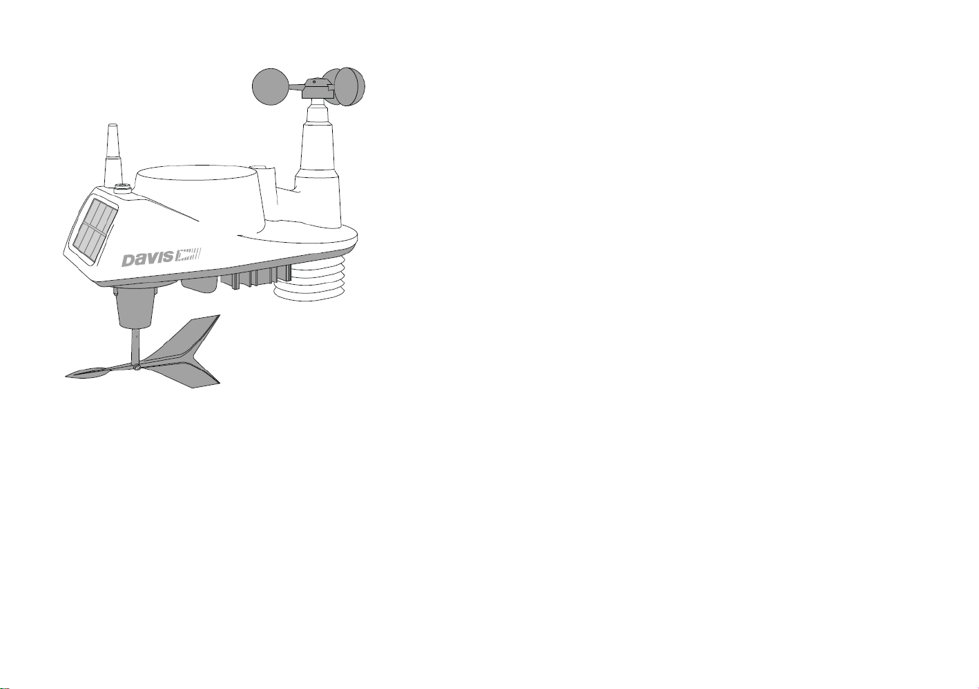
Table of content
Introduction
List of components
Preparing ISS for installation
Anemometer
Wind Vane
Debris screen
Wind speed sensor
Multicontrol
Installing of battery
Advanced installation
Short range and long range transmitters
Verication of data from ISS
Installing of ISS
Mounting thge ISS
Installing of ISS on the pole
Maintenance and troubleshooting
Guidelines for installation of PX4
Apendix A
Installation of battery pack
2
3
6
7
8
9
10
11
12
14
15
16
17
18
22
23
25
26
28
Page 3

FCC Part 15 Class B Registration Warning
is equipment has been tested and found to comply with the limits for a Class B digital device, pursuant to Part
15 of the FCC Rules. ese limits are designed to provide reasonable protection against harmful interference in
a residential installation. is equipment generates, uses, and can radiate radio frequency energy and, if not
installed and used in accordance with the instructions, may cause harmful interference to radio communications.
However, there is no guarantee that interference will not occur in a particular installation. If this equipment does
cause harmful interference to radio or television reception, which can be determined by turning the equipment on
and o, the user is encouraged to try to correct the interference by one or more of the following measures:
•Reorient or relocate the receiving antenna.
•Increase the separation between the equipment and receiver.
•Connect the equipment into an outlet on a circuit dierent from that to which the receiver is connected.
•Consult the dealer or an experienced radio/TV technician for help.
Changes or modication not expressly approved in writing by Davis Instruments may void the warranty and void
the user’s authority to operate this equipment.
FCC ID: IR2DWW6357IC: 3788A-6357
is product (models 6250EU, 6250UK, 6357OV complies with the essential protection requirements of the
Radio Equipment Directive 2014/53/EU. e complete Declartion of Conformity is one our website at https://
www.davisnet.com/legal. RoHS Compliant.
Integrated Sensor Suite Installation Manual
Rev. F, 8/1/17
Document Part Number: 07395.262
For Vantage Vue Weather Stations and Systems
System is ISO 9001 certied.out notice. Davis Instruments
Quality Management Information in this document subject
to change with-© Davis Instruments Corp. 2012.
All rights reserved.Hayward, CA. Envoy™ are trademarks of
Davis Instruments Corp., , Vantage Pro2™, and Weather ®Vantage Vue
3465 Diablo Avenue, Hayward, CA 94545-2778 U.S.A.
510-732-9229 • Fax: 510-732-9188
E-mail: info@davisnet.com • www.davisnet.com
1
®
Page 4

Introduction
2
The Vantage Vue® wireless Integrated Sensor Suite (ISS) collects outside weather data
and sends the data wirelessly to a Vantage Vue console via a low-power radio. The ISS is
solar powered and includes a battery back-up.
The Vantage Vue ISS contains a rain collector, temperature/humidity sensor,
anemometer, and wind vane. The temperature/humidity sensor is mounted in a passive
radiation shield to minimize the impact of solar radiation on sensor readings. The
anemometer measures wind speed, and the wind vane measures wind direction.
The Sensor Interface Module (SIM) is housed within the ISS and comprises the “brains”
of the Vantage Vue system and the radio transmitter.
The SIM collects outside weather
data from the ISS sensors and transmits that data to your Vantage Vue console.
Note: Your Vantage Vue ISS can transmit to an unlimited number of consoles, so you can purchase addi-
tional consoles to use in different rooms. It can also transmit to Davis Vantage Pro2 consoles and
Davis Weather Envoys as well as Vantage Vue consoles.
Included Components and Hardware
Vantage Vue ISS Components
Page 5
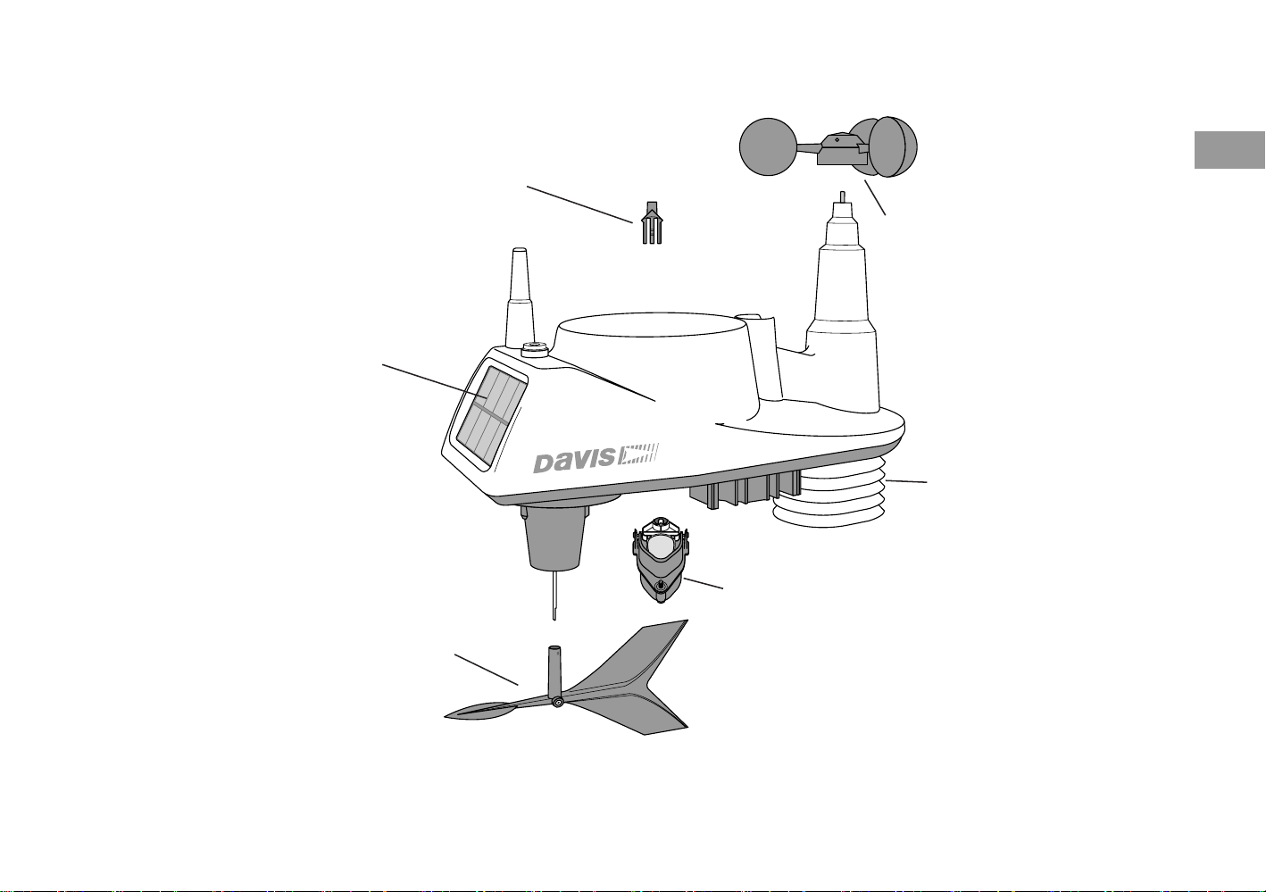
Rain collector
debris screen
Solar panel
Wind vane
3
Wind cups
shield
Tipping spoon
(rain) assembly
Page 6
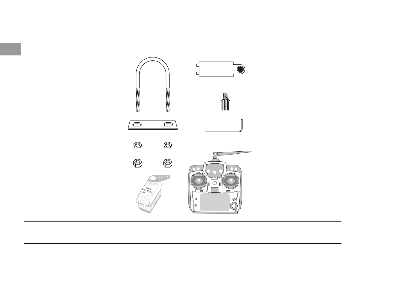
Hardware
4
Hardware included with the Vantage Vue ISS:
U-Bolt
Backing plate
1/4” lock washers
1/4” hex nuts
Servo
Battery cover with
thumbscrew
Debris screen
0.05”
Allen wrench
Remote align unit
Note: If any of the hardware components are missing or not included, contact Customer Service toll free at
1-800-678-3669 about receiving replacement hardware or other components.
00-86-579-8230-6111
Tools Needed
•A
djustable wrench or 7/16” (11 mm) wrench
•Compass or local area map
Page 7

Full Windnder meteo station Pro+ include
- Davis Vantage Vue core unit
- Meteo Bridge Pro+
- APM 2.8 wind speed measurement control unit with power module and wind
speed sensor
- PX4 2.4.6 air quality measurement control unit with air quality sensor
- Pole xing mechanism with servo and Radiolink remote rotation controller
- Wind cups, rain collector, sun shield
- Data transmission unit RFD900 with CM921
- Battery pack LiPo battery with DC-DC 0.591, S-21AL and Ubec 5-7.5A
- Wind vane
- Assembly material
- Assembly tools
Find out more optional equipment or spare sensors on www.mfd-tools.com
5
Page 8

Preparing the ISS for Installation
6
Note: Use a clean, well-lit work table or work area to prepare the ISS for installation.
Note: At this point, we recommend that you set up your console, and then come back to finish the installation of
Follow the steps in the order; each builds on tasks completed in previous steps.
1. Attach the wind cups to the anemometer
2. Attach the wind vane
3. Install the rain collector tipping spoon assembly
4. Install the debris screen in the rain collector
5. Install the ISS battery to apply power
the ISS. See your Vantage Vue Console Manual.
Additional steps for advanced set up:
•Verify transmitter ID
•Change the transmitter ID for wireless communication, if necessary
6. Verify data from the ISS
Page 9
Attach the Wind Cups to the Anemometer
The Vantage Vue anemometer measures wind speed. The wind cups are mounted on the
anemometer shaft on the top of the ISS assembly.
1. Gently slide the wind cup assembly
down onto the anemometer’s
stainless steel shaft as far as it will
go, as shown.
2. Use the Allen wrench provided to
tighten the set screw near the top of
the “hub” section of the wind cups,
as shown. Ensure that the set screw
is screwed in fully and is tight.
3. Pull gently on the hub to ensure
that the anemometer is securely
fastened to the shaft.
4. Spin the wind cups to make sure
they spin freely.
7
K
Note: If the wind cups don’t spin freely, loosen the set screw, remove them from the shaft, and repeat the wind
cup installation process.
Page 10
Attach the Wind Vane
The Vantage Vue wind vane measures wind direction. The wind vane is mounted on a stainless
steel shaft on the opposite side of the ISS assembly from the wind cups.
8
1. Hold the ISS assembly on its side with
the anemometer and radiation shields
on your left, the wind vane shaft on
your right and the wind cups away
from you.
2. When the ISS is held in this manner,
the wind vane shaft is horizontal, and
will orient itself so that its flat side will
be facing to the right, as shown.
3. Holding the ISS assembly with your
left hand, grasp the wind vane with
your right hand so that the “arrowhead” end is pointed down.
4. Gently slide the wind vane onto the wind vane shaft, rotating the wind vane slightly left and
right if necessary, until the end of the shaft is visible and protrudes slightly from the bottom
surface of the wind vane.
PX4 unit
5. Secure the wind vane to the shaft by firmly tightening the wind vane set screw with the
Allen wrench provided.
Page 11

Install the Rain Collector Tipping Spoon
Assembly
1. Locate the tipping spoon assembly slot on the
underside of the ISS Base.
2. Insert the wider end of the tipping spoon assembly
into the slot first, sliding it under the raised lip of the
slot.
3. Fit the narrow end into the slot and tighten the
thumbscrew securely.
Install the Debris Screen
The Vantage Vue ISS rain collector debris screen captures
debris that may otherwise clog your rain collector.
1. Locate the small black plastic ISS debris screen in your
hardware package.
The debris screen has four small tabs that hold it in place
in the base of the rain collector.
2. Holding the ISS assembly with one hand, and holding the
debris screen by the top, press it into the opening in the
rain collector until the tabs snap into the opening.
Tipping spoon
assembly
Tipping spoon
assembly slot
9
Page 12

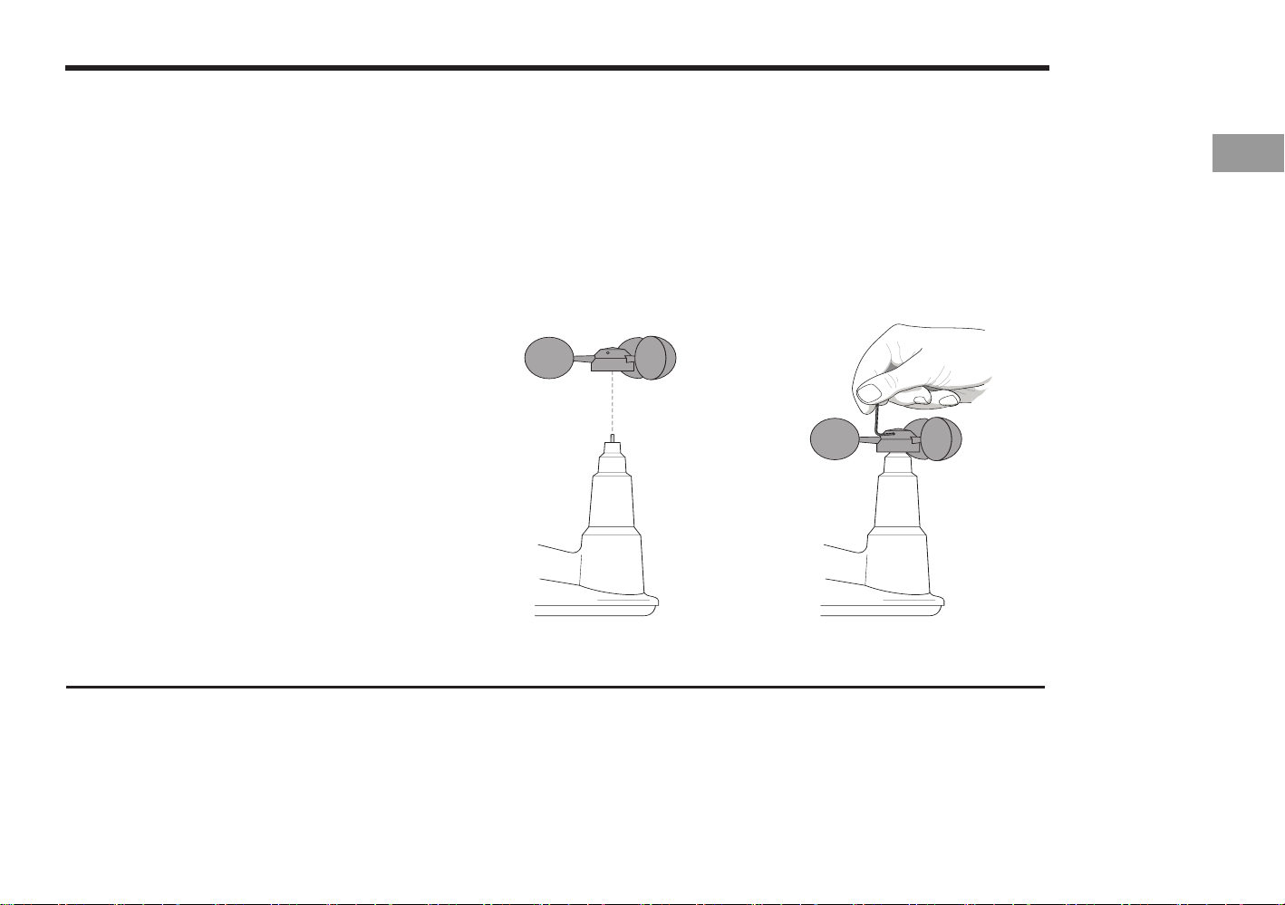
Install the wind speed and direction sensor
1. Remove the typing spoon assembly
10
2. Connect APM sensor unit to data input cable inside
typing spoon assembly
3. Connect APM sensor unit to data output cable inside
Pro+ body
4. Connect power source cable to APM sensor unit
5. Attach wind sensor to plastic tubes and
attach sensor to APM
6. Attach whole APM sensor and unit to
typing spoon assembly and use screws
to tighten spoon assembly to ISS body.
Data outputs
/ connect meteostation data input here
Data outputs
/ connect meteostation data output here
Power
Meteostation
telemetry
Wind speed sensor
Page 13

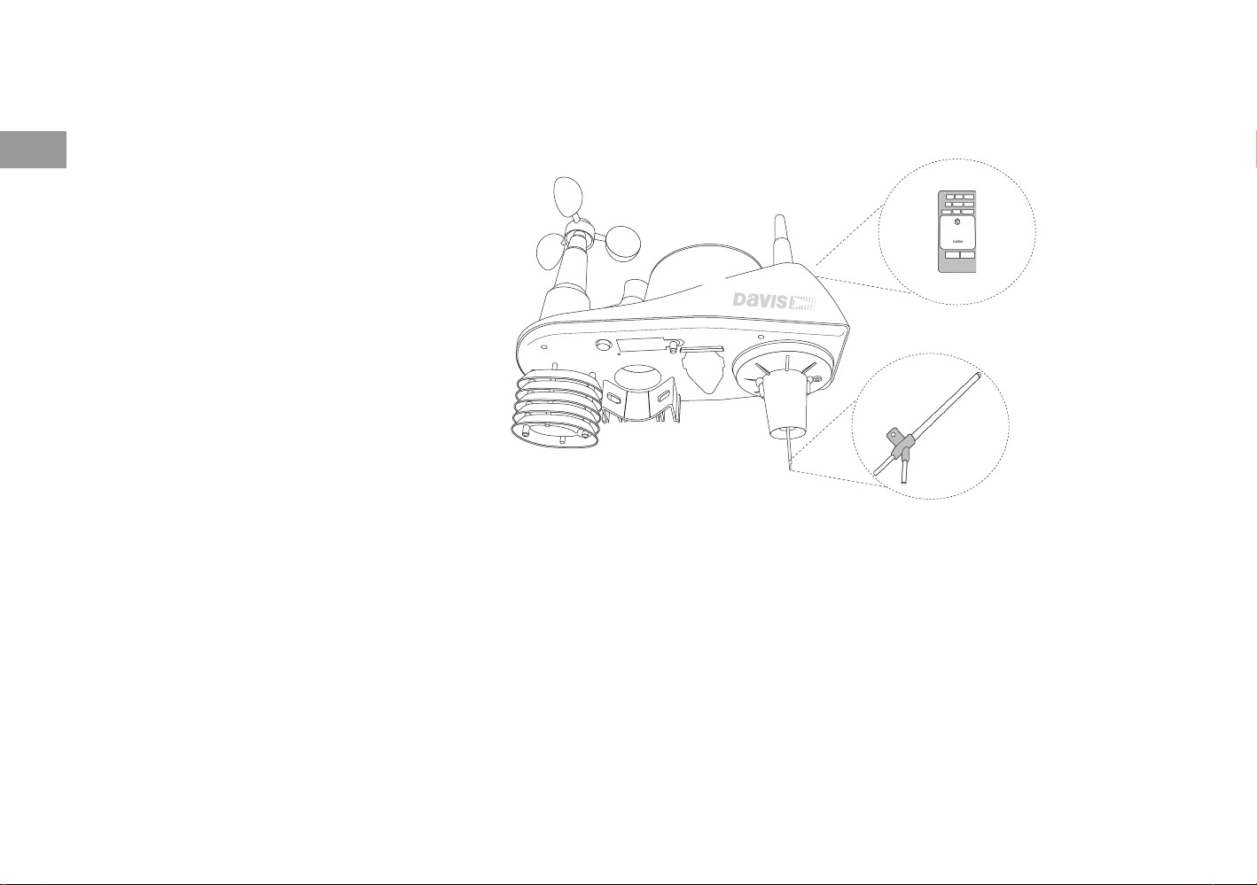
Control up to 12 Vantage Vue stations
If you are controling wind park or large scale agriculture areas, you can control 12 meteo stations in the same time.
Vantage Vue Pro+ meteo station is supplied with 12CH radio controller allowing pairing with 11 other meteo stations.
Main functions of radio controller:
1. changing of direction of meteo station / this allows precise measuring of wind direction, wind speed, dust, temperature
2. real time weather data on LCD display
3. weather model from all 12 meteo station on same LCD display
4. turning on and o sensors on selected meteo station
5. remote calibration and analisys
11
Page 14

12
Install the Battery
The Vantage Vue ISS SIM board stores energy from the solar panel for power at night. A 3volt lithium battery provides a backup power source. The battery compartment is located on
the underside of the ISS base. The compartment cover is included in the hardware packet.
To install the ISS backup battery.
1. Insert the 3-volt lithium battery into
the ISS battery compartment, being
sure to match the “+” sign on the
battery with the “+” sign embossed
on the inside of the battery
compartment.
Transmitter ID
pushbutton
Battery
compartment
2. Ensure that the battery is properly in
place, install the battery compartment cover, and tighten the thumbscrew.
Transmitter ID
LED
Battery compartment
cover
To verify power, wait 30 seconds
then push and release the white transmitter ID pushbutton next to the battery compartment.
The green transmitter ID LED next to the battery compartment will illuminate when you
press the pushbutton.
Note: Press the pushbutton once and release it. Do not press it multiple times or hold it down.
Page 15

When you release the pushbutton, the LED will blink once (indicating transmitter ID 1),
then begin to flash every 2.5 seconds to show transmission of a data packet. This flashing
will stop within a few minutes to conserve battery life.
Note: If you have not already set up and powered your Vantage Vue console, do so before continuing with the
ISS installation. For best reception, the console and ISS should be at least 10 feet (3 meters) apart.
3. The console acquires the radio signal and populates data fields. This usually occurs quickly,
but in some enviromental conditions it can take up to 10 minutes.
Advanced Installations: Confirm the Transmitter ID of the ISS
Your Vantage Vue console can be used to listen to a Vantage Pro2 ISS instead of a Vantage
Vue ISS, and an optional anemometer transmitter kit.
Note: If you are using only the Vantage Vue console and ISS, and there are no other Davis weather stations
nearby, you can skip to “Verify Data from the ISS” on page 6.
In order to communicate, the console and ISS
must have the same transmitter ID. At the
factory, both IDs are set to a default of number 1. To confirm the transmitter ID of your
Vantage Vue ISS:
13
1. Push and release the transmitter ID
pushbutton once. It will illuminate and go
off when you release it.
2. After a short pause, it will blink one or
more (up to 8) times. Note the number of
Transmitter ID
pushbutton
Transmitter ID
LED
Page 16

Note: The transmitter on the ISS and receiver on the console will communicate with each other only when both
are set to the same transmitter ID.
14
Note: If you hold the pushbutton too long and accidentally enter the “set new transmitter ID” mode when you did
not want to, simply release the pushbutton and wait four seconds. As long as you do not press the pushbutton again, the original transmitter ID will remain in effect.
Advanced Installations: Set a New Transmitter ID on the ISS
Note: In most cases, it will not be necessary to change the transmitter ID. If it is necessary to change the trans-
mitter ID, you must use the same ID for the ISS and console.
The Vantage Vue ISS transmits weather information to the Vantage Vue console using one of
eight selectable transmitter IDs. The default transmitter ID for both the ISS and the Vantage
Vue console is 1. Change the transmitter ID if another Davis Instruments wireless weather station is operating nearby and already uses transmitter ID 1, or if you have an optional Ane-
To set a new transmitter ID:
1. Push and hold the transmitter ID pushbutton until the LED begins flashing quickly. This
indicates it is in the setup mode.
2. Release the pushbutton, and the LED will go dark.
3. Push the pushbutton the number of times equal to your desired new transmitter ID. That is,
if you want to change the ID to “3,” push the pushbutton three times; for a desired ID of
“4,” push the pushbutton four times.
After four seconds have elapsed with no further presses, the LED will blink the same num-
ber of times as the new transmitter ID. (After blinking the transmitter ID number, the light
will begin to flash each time a packet is transmitted, about every 2.5 seconds.)
Page 17

Installing of short range and long range Transmitters
The Vantage Vue ISS is standardly supplied with short range transmission modem. Install
short range modem by connecting of Vantage Vue ISS with FTP cable and attaching of antena.
NOTE: Vantage Vue ISS is supplying short range modem with energy through connection cable. Use short range
modem for distance of max. 25 m.
For long range distance over 25m use special RFD900 modem with CM921 transciever.
Install RFD900 inside Vantage Vue main board by using of LRM socket. RFD900 is supplied
by energy from main board of Vantage Vue.
Connect RFD900 to external CM921 transceiver.
RFD900
CM921
15
NOTE: Special RFD900 modem with external CM921 transceiver can be used for long range distance up to 200m
of open area depending on weather conditions.
NOTE: RFD900 and CM921 are not supplied with standard version of Vantage Vue unit. You can order RFD900
and CM921 with special version Vantage Vue Pro+
Page 18

Verify Data from the ISS
To verify reception of ISS data by the Vantage Vue console, you will need your powered-up
16
console and the ISS. For best reception, the console and ISS should be at least 10 feet (3
meters) apart.
1. If the console is in Setup Mode, press and hold DONE until the Current Weather screen
displays. The antenna icon appears under the wind compass rose. Watch this icon to see
that “transmission waves” appear, indicating reception of a packet.
Sensor readings from the ISS should display on the screen within a few minutes.
2. At the top right corner of the screen, look for the outside temperature.
3. Gently spin the wind cups to check wind speed, pressing the WIND button on the console
to alternate between speed and direction in the windcompass rose.
4. Gently turn the wind vane, and allow 5 seconds for the wind direction display to stabilize
before moving it again.
Note: A good way to ensure that your console is listening to your ISS and not another Davis station nearby, is to
make sure the wind values displayed match your wind vane’s direction in reference to the solar panels,
which are assumed to be facing south. For example, if you move the vane to point directly away from the
ISS, the console should show a wind direction of south; if you then turn the vane 180
back at the radiation shield, the wind direction on the console should change to nor th.
° so it is pointed
5. Approximately one minute after acquisition of the signal, the outside relative humidity
reading should be displayed on the console, below the outside temperature display.
6. Confirm rain display. On your console screen, select the RAIN DAY display. (See Vantage
Vue Console Manual.). Carefully hold your ISS over a sink and, while watching the RAIN
DAY display on your console, slowly pour one-half cup of water into the Rain Collector.
Wait two seconds to see if the display registers a rain reading.
Note: This method confirms that the rain display is functioning. It cannot be used to verify accuracy.
Page 19

Installing the ISS
Choosing a Location for the ISS
The ISS assembly includes the rain collector, wind vane, anemometer, temperature and
humidity sensors, radiation shield, and SIM housing. You will use the U-bolt and associated
nuts and washers that are included with your ISS mounting hardware package to install the ISS
on a pole. (See “Hardware” on page 2.)
To ensure that the Vantage Vue weather station performs at its best, use these guidelines to
select the optimum mounting location for the ISS. Be sure to take into consideration ease of
access for maintenance and wireless transmission range when siting the station.
Note: When selecting a location for installing your ISS, especially on a rooftop, make sure it is a location far
from power lines. Seek professional help if you are uncertain about the safety of your installation.
ISS Installation Guidelines
Note: These siting guidelines reflect an ideal condition. Rarely is it possible to create the perfect installation.
The better the siting, the more accurate your data will be.
17
•Place the ISS away from sources of heat such as chimneys, heaters, air conditioners and
exhaust vents.
•Place the ISS at least 100' (30 m) away from any asphalt or concrete roadway that readily
absorbs and radiates heat from the sun. Avoid installations near fences or sides of build-
ings that receive a lot of sun during the day.
Page 20

•Install the ISS as level as possible to ensure accurate rain and wind measurements. Use the
built in bubble level on the top of the ISS, just above the solar panel, to make sure the ISS
is level.
18
•In the Northern Hemisphere, the solar panel should face south for maximum sun exposure.
•In the Southern Hemisphere, the solar panel should face north for maximum sun exposure.
SOUTH
(in the Northern
Hemisphere)
NORTH
(in the Southern
Hemisphere)
Note: If you install the ISS with the solar panel pointing in a direction other than south, you will need to use the
wind direction calibration function in the Vantage Vue console in order to obtain accurate wind direction
readings. See Vantage Vue Console Manual for more information.
Solar Panel
Mounting the ISS
The Vantage Vue ISS can only be mounted on the top of a pole or rod.
Note: A mounting pole is not included with your Vantage Vue ISS and must be purchased separately, either
from Davis Instruments or from your local hardware retailer.
Page 21

Recommended Accessories for Pole Mounting
• Use the Mounting Tripod (#7716) for easiest mounting.
General Guidelines for Installing on a Pol
lon-
the
• Use the Mounting Pole Kit (#7717) to raise the installation height of the ISS by up to
37.5" (0.95 m).
•With the supplied U-bolt, the ISS can be mounted on a pole or rod having an outside
diameter ranging from 1" to 1.75" (25 – 44 mm).
•To mount on a smaller pole, obtain a U-bolt that fits the base openings but that has a
ger threaded section. If mounting the ISS on a smaller pole with the included U-bolt,
threaded sections of the U-bolt will be too short to securely mount the ISS.
19
e
C-shaped
bracket
Page 22

General Guidelines for Installing of Vantage Vue Pro+ conguration
Recommended Accessories for Pole Mounting
• Use the Mounting Tripod (#7716) for easiest mounting.
• Use the Mounting Pole Kit (#7717) to raise the installation height of the ISS by up to
37.5" (0.95 m).
General Guidelines for Installing on a Pole
lon-
the
•With the supplied U-bolt, the ISS can be mounted on a pole or rod having an outside
20
diameter ranging from 1" to 1.75" (25 – 44 mm).
•To mount on a smaller pole, obtain a U-bolt that fits the base openings but that has a
ger threaded section. If mounting the ISS on a smaller pole with the included U-bolt,
threaded sections of the U-bolt will be too short to securely mount the ISS.
• Attach bolts to supplied servo motor and secure bolt to ISS body. Test, if the rotation
around the pole with servo motor is going freely and tighten screws to C-shaped
bracket.
Page 23

• Use remote controller and slowly test rotation of ISS unit to the le and right and
following movement up to down.
• Use remote controller to set correct direction of Vantage Vue Pro+ station to
preered direction.
NOTE: Remote controller is not part of basic package Vantage Vue. Order remote controller separately.
NOTE: Use display of remote controller to change settings of Vantage Vue Pro+ station.
NOTE: Use display of remote controller to see real time data from Vantage Vue Pro+ station.
21
Page 24

Installing the ISS on a Pole
1. If you are mounting your ISS on a Davis Mounting Tripod or the pole included with a
22
Davis Mounting Pole Kit, follow the instructions included with those Davis products for
proper installation.
If you are not using one of these Davis products, mount on a galvanized steel pole having
an outside diameter ranging from 1" to 1.75" (25 – 44 mm).
Note: It is important that the mounting pole be plumb. You may wish to use a level such as a magnetic ”torpedo
level” to assure that the ISS, when mounted on top of the pole, will be level.
2. Using the illustration above as a guide, hold the ISS so that the wind cups and radiation
shield are on the left and gently place the ISS on top of the pole.
3. While holding the mounting base of the ISS against the pole, place the two ends of the Ubolt around the pole and through the two holes in the C-shaped bracket on the base.
4. Slide the metal backing plate over the bolt ends where they extend out from the far side of
the bracket.
5. Secure the backing plate with a lock washer and hex nut on each of the bolt ends, as shown
in the illustration.
6. Tighten the hex nuts with your fingers only so that the ISS is just secure enough on the
pole for you to release your grip.
Note: Always test remote rotaon of the meteo unit aer installaon to prevent
blocking of rotaon in strong wing condions. Slowly move with the levers to
the le and right before you will make full 360° rotaon.
Page 25

Maintenance and Troubleshooting
Maintenance
Cleaning the Radiation Shield
The outer surface of the radiation shield should be cleaned when there is excessive dirt and
build-up on the plates. Use a damp cloth to clean the outer edge of each ring.
Note: Spraying down or using water excessively to clean the radiation shield can damage the sensitive sensors
or alter the data the ISS is transmitting.
Check the radiation shield for debris or insect nests at
least once a year and clean when necessary. A buildup
of material inside the shield reduces its effectiveness
and may cause inaccurate temperature and humidity
readings.
1. Using a Phillips head screwdriver, loosen the two
#6 x 2
plates together, as shown.
2. Taking care to maintain the order in which the five
plates are assembled, separate the plates as shown
and remove all debris from inside the shield.
1
/
” screws holding the five radiation shield
2
23
3. Reassemble the plates in the same order in which
they were disassembled, and fasten them together
using a Phillips head screwdriver to tighten the #6
1
x 2
” screws, as shown.
/
2
Page 26

To maintain accuracy, thoroughly clean the rain collector cone and debris screen as needed or
at least once a year.
Note: Cleaning the rain collector and tipping spoon may cause false rain readings. See “Clearing Data Col-
24
lected During Testing and Installation” on page 10.
1. Use a damp, soft cloth to remove any debris from the rain collector and debris screen.
2. Use pipe cleaners to clear any debris remaining in the screen.
3. When all parts are clean, rinse with clear water.
To clean the tipping spoon assembly, it must first be removed from the ISS base.
To maintain accuracy, thoroughly replace the wind speed sensor as needed or at least once a
month depending on air pollution or dust concetration.
Calibration of Wind Sensor Control Unit is not possible. It is recommended to replace Wind
Sensor Control APM 2.8 Unit once a year.
Wind sensor control unit
Wind speed sensor
Page 27

Guidelines for Installing of PX4 temperature and humidity sensor unit
• Install PX4 inside Vantage Vue main body and connect PX4 to socket
• Use this schema to connect required meteo sensor modules
1. Power module 1
2. Power module 2
3. Telemetry 1
4. USB
5. Telemetry 2
6. CAN1
7. splitter for additional sensors
8. CAN2
9. S BUS
10. PPM receiver input
11. PWM out main outputs
12. UART and I2C
13. DSM/SBUS receiver input
14. ADC IN capture
15. Galvanic Pressure Sensor module
16. SPI bus
17. AUX outputs
1
2
3
4
5
6
7
8
4
9
10
11
1
2
4
25
12
13
14
15
16
17
NOTE: Handle with care. PX4 is sensitive agains static electric body shock. Install PX4 by using body static elec-
tricity grounding.
NOTE: PX4 is equipped with interface for external magnetometer. Use Magnetometer IST8310.
NOTE: PX4 is equipped with interface for external barometer. Use Barometer MS5611.
Page 28

Troubleshooting
26
1. Unscrew the thumbscrew securing the tipping spoon
assembly to the ISS base. Slide the assembly down and
away from the base.
2. Use a damp, soft cloth to gently remove any debris from
the tipping spoon assembly, being careful not to damage
any moving parts or scratch the spoon.
3. When all parts are clean, rinse with clear water, and
replace the assembly. (See “Install the Rain Collector
Tipping Spoon Assembly” on page 4.)
4. Replace Air Quality PX4 2.4.6 Measurement Unit
Solid plates,
drain holes
toward
mounting pol
e
Page 29

Appendix A: Specifications
See complete specifications for your Vantage Vue station on our website:
www.mfd-tools.com
Integrated Sensor Suite (ISS) Specifications
Operating Temperature .................................. .- 40° to +150°F (-40° to +65°C)
Non-operating (Storage) Temperature ........... .-40° to +158°F (-40° to +70°C)
Current Draw (ISS SIM only) .......................... .0 .20 mA (average), 30 mA (peak) at 3.3
VDC
Solar Power Panel (ISS SIM) ......................... .0 .5 Watt s
Battery (ISS SIM) ............................................ CR-123 3-Volt Lithium cell
Battery Life (3-Volt Lithium cell) ..................... .8 months without sunlight - greater than
2 years depending on solar charging
Wind Speed Sensor ...................................... .W ind cups with magnetic detectio n
Wind Direction Sensor .................................. .W ind vane with magnetic encode r
27
Rain Collector Type ...................................... .T ipping spoon, 0.01" per tip (0.2 mm
with metric rain cartridge, Part No.
2
7345.319), 18.0 in
area
Temperature Sensor Type ............................. .P N Junction Silicon Diode
Relative Humidity Sensor Type ...................... .F ilm capacitor element
Housing Material ............................................ .U V-resistant ABS & ASA plasti c
(116 cm2) collection
Page 30

28
Update Interval by Sensor
Barometric Pressure1 min.
BAR
Inside Humidity 1 min.
Outside Humidity 50 sec.
HUMIDITY
Rainfall Amount 20 sec.
Rain Storm Amount 20 sec.
RAIN
Inside Temperature1 min.
Outside Temperature 10 sec.
TEMPERATURE
Wind Speed2 .5 sec.
Wind Direction2 .5 sec.
WIND
Direction of High Speed2 .5 sec.
.ces 01tnioP weD
.ces 02etaR niaR
.ces 01xednI taeH
.ces 01llihC dniW
Page 31

Installation of back-up battery pack
Windnder Davis Vantage Vue is supplied with standard 3V lithium battery for night regime. Use additional LiPo
battery for Vantage Vue in conguration Pro+ to cover high energy consumption of long distance transmitter RFD
and CM921.
Always connect Vantage Vue station to external source of power with current and voltage stabilizer. Use voltage
stabilizer stabilizing voltage in range from 0.591V to 6V max. Use current stabilizer 5-7.5A UBEC type.
NOTE: Never connect Vantage Vue to external source of power without voltage and current stabilizer. You may risk
damage of sensors or improper functionality.
NOTE: Current stabilizer and voltage stabilizer are not supplied standardly for Vantage Vue basic package
NOTE: It´s recomended to use 5 500 mAh LiPo type battery for Vantage Vue station in conguration Pro+
NOTE: LiPo battery is not part of supply with Vantage Vue package.
29
Current stabilizer
LiPo battery
Page 32

Windnder online application Authorized dealer
WindFinder.com GmbH & Co. KG
Boltenhagener Str. 4
24106 Kiel
Germany
Registered oce:
Kiel, Commercial register: Kiel HRA 6742 KI
VAT-No.: DE268454511
Phone: +49 431 800 86 43
Fax: +49 431 800 86 44
E-mail: info@windnder.com
Web: www.windnder.com
MFD-Tools Co. Ltd.
Tangwang Industrial Park, Pengije Town
Luqiao District, Taizhou City
Zhejiang Province
China
Phone: +86 579 8230 6111
E-mail: info@mfd-tools.com
Web: www.mfd-tools.com
Telephone support availability
Telephone support is only available for advertising and business con-
tacts. We oer free email support for all website and app users.
You can nd answers to our most Frequently Asked Questions (FAQ) in
our help section as well as in the Help menu inside our apps.
You can contact us for email support here: support@windnder.com
 Loading...