

Page 1
Integrated Sensor Suite with
Fan-Aspirated Radiation Shield
Installation Instructions Addendum
For Vantage Pro2™ and Vantage Pro2 Plus™
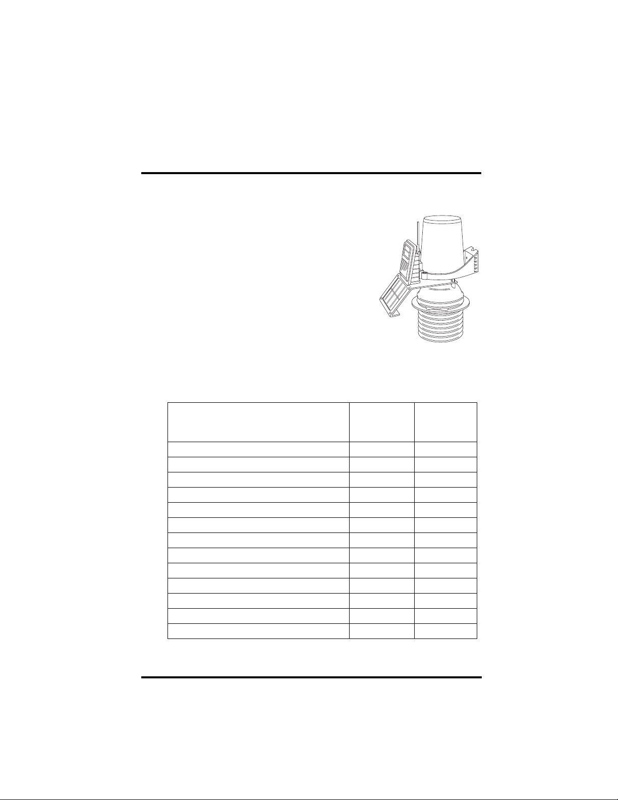
The Vantage Pro2™ Integrated Sensor Suite (ISS)
with the Fan-Aspirated Radiation Shield uses a
combination of fan-aspiration and shielding to
minimize temperature measurement errors due to
the effects of solar radiation.
Fan-Aspirated ISS Addendum
Overview
This addendum provides additional information
specific to the installation and use of ISS models
containing the fan-aspirated radiation shield. It is
intended to be used in conjunction with the “Integrated Sensor Suite Installation Manual.”
The table below shows the location of the information required to install and
maintain your Fan-Aspirated ISS system.
Section/Procedure
Tools for Setup X
Preparing the Anemometer X
Preparing the Rain Collector XX
Preparing the Radiation Shield X
Powering ISS and Testing Communications X
Powering and Testing the Fan X
Choosing a Site for the ISS X
Mounting the ISS X
Additional Mounting Options X
Fan-Aspirated Shield Maintenance X
Theory of Operation X
Fan-Aspirated Shield Troubleshooting X
Fan-Aspirated Shield Specifications X
In This
Addendum
In the ISS
Installation
Manual
1
Page 2
Fan-Aspirated ISS Addendum Overview
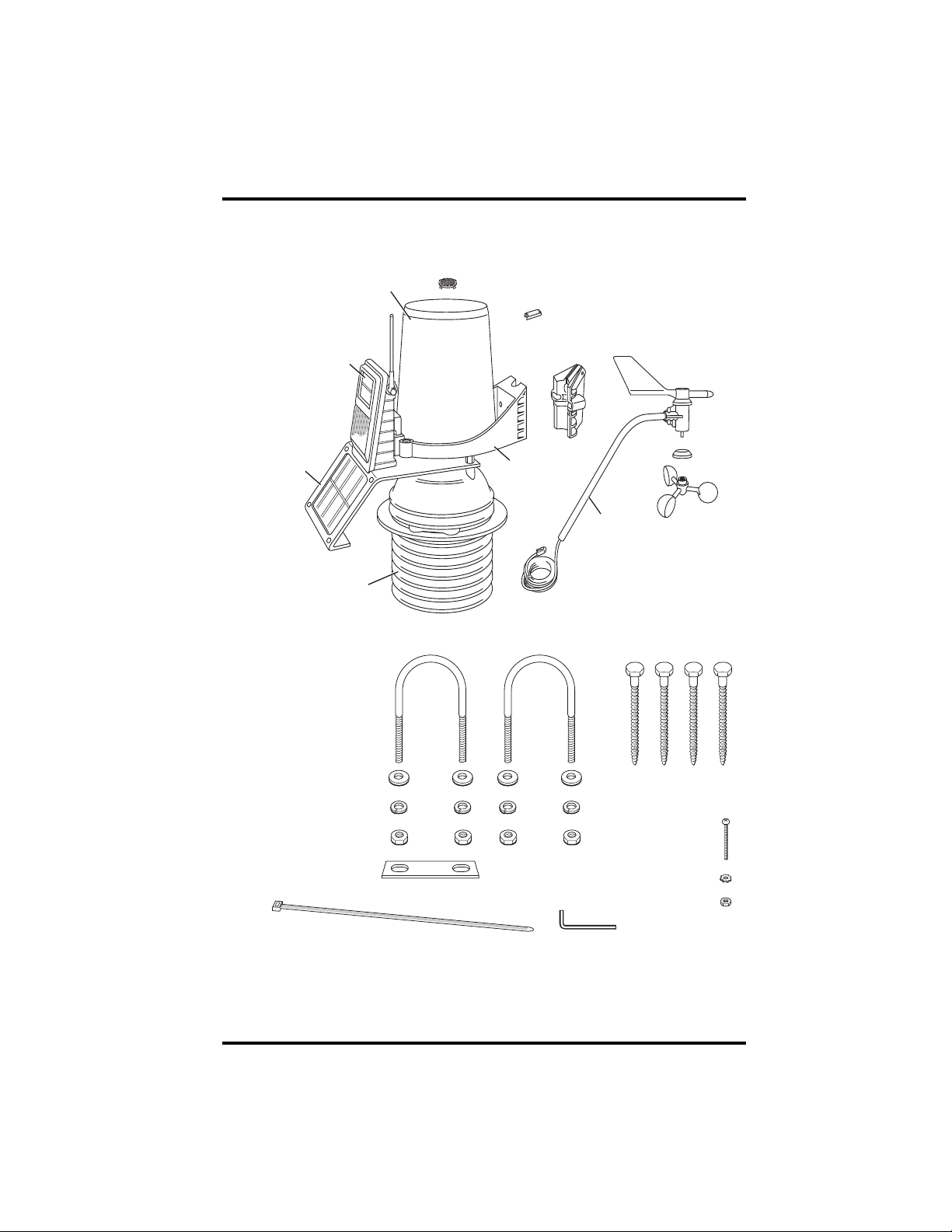
Components
The Fan-Aspirated ISS includes these components:
Rain Collector
Solar Panel
(Wireless
SIM only)
SIM
Housing
Fan
Solar Panel
Aspirated
Radiation
Shield
Debris Screen
(Place inside cone after installation)
Metric
Rain Adapter
Anemometer
ISS Base
Base
Anemometer
Arm
Anemometer Cable
40’ (12.2 m)
Anemometer
Vane
The hardware shown here is provided for assembly and mount ing:
U-Bolts
Control
Head
Drip Ring
Wind Cups
1/4" Flat Washers
1/4"x x3" Lag Screws
1/4" Lock Washers
1/4" Hex Nuts
Backing Plate
#4 Tooth Lock Washer
#4 x 1-1/8
Machine Screw
#4-40 Hex Nut
8" Cable Tie
.05"
Allen Wrench
2
Page 3
Tools for Installation
f
Additional Components on Vantage Pro Plus
The Vantage Pro2 Plus™ includes an ultraviolet
(UV) sensor and a solar radiation sensor. These
two sensors are mounted next to the rain collector on your ISS.
See the Integrated Sensor Suite Installation
Manual about mounting and maintaining these
sensors.
Do not to touch the small white diffusers on top
of the UV and solar radiation sensors. Oil from
the skin reduces sensor sensitivity.
Tools for Installation
Refer to this section in your ISS Installation Manual for the tools needed to
assemble the ISS.
Preparing the ISS for Installation
Refer to this section in your ISS Installation Manual on assembling the ISS.
Preparing the SIM for Installation
The ISS sensors are connected by cables to the Sensor Interface Module
(SIM), located inside the SIM housing. The SIM contains electronics that
measure and store weather information for transmission to the console via
radio. The SIM housing protects the SIM from the elements and provides easy
access to the SIM cable connections.
See the ISS Installation manual on checking the sensor connections to the SIM
and for any additional sensor and wireless installation instructions.
UV and Solar
Sensors
Sensor
Mounting Shel
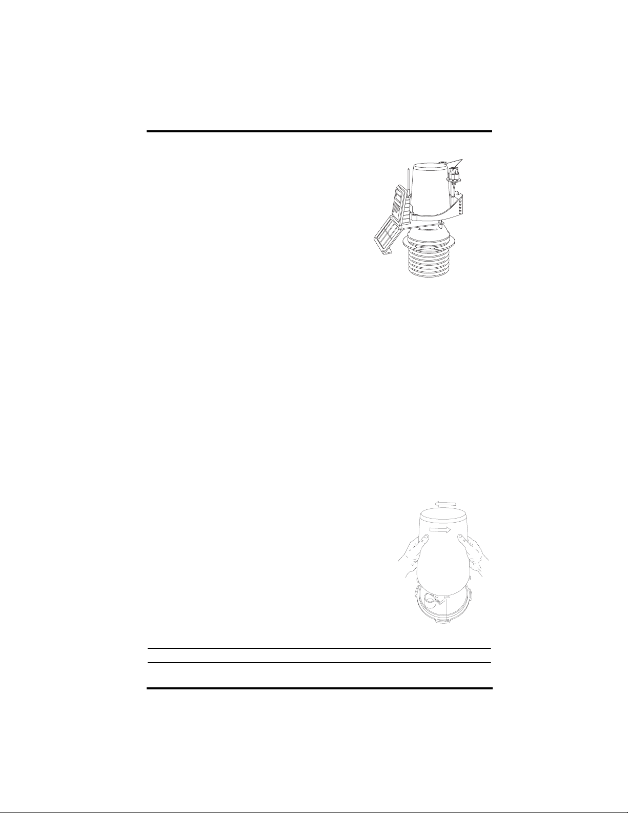
Preparing the Rain Collector
1. Remove the rain collector cone from its base by
rotating the cone counter-clockwise until its
latches line up with openings which allow you
to lift it off. The cone fits in the base tightly and
may require extra pressure to remove it when
new.
Twist off the rain collector cone
Note: Steady the base between your knees when you rotate the rain collector.
3
Page 4

Preparing the Fan-aspirated Shield for Installation
2. Carefully cut and remove the plas-
Tipping bucket mechanism
tic tie (usually black in color) that
holds the two-sided tipping bucket
mechanism in place during shipping.
3. See the ISS Installation Manual for
instructions on inserting the
optional metric measurement
adapter.
Cut the plastic tie
Preparing the Rain collector
Preparing the Fan-aspirated Shield for Installation
The radiation shield, fan, and solar panel used to power the fan come preassembled with the ISS unit and requir e no addi tio nal as sembl y. However, the
fan requires initial power from the pre-installed batteries. Tabs are included to
ensure that the batteries installed in the fan-aspirated housing do not power the
unit during shipping. To power the fan-aspirated unit:
1. Pull the battery tabs out slowly.
2. Listen for a slight whir coming from the bottom of the
ISS unit. This sound signifies that the fan is running.
Applying Power and Testing Communications
Refer to the Wireless ISS Assembly section in your ISS Installation Manual
for the rest of the procedures required to power and test the ISS.
Locating the ISS and Anemometer
Refer to this section in your ISS Installation Manual.
Mounting the ISS
Refer to this section in your ISS Installation Manual.
Additional Mounting Options
Refer to this section in your ISS Installation Manual.
Fan-Aspirated Shield Batteries
The Fan-Aspirated shield is solar powered and is supplied with two NiCad Ccell batteries that come pre-installed. The following options for battery power
exist:
• Use two fan batteries for maximum length of overnight aspiration but with
slightly lower average daytime aspiration.
4
Page 5

Fan-Aspirated Shield Maintenance
• Use only one fan battery for some overnight aspiration but with slightly
higher average daytime aspiration.
• Remove both batteries for maximum daytime aspiration and no nighttime
aspiration. See “Replacing Fan Motor and Batteries” on page 6 for more
information.
Fan-Aspirated Shield Maintenance
• Keep the outer surfaces clean, since the unit is less effective when the surfaces are dirty. Remove dust from the solar panel and the shield with a
damp cloth. Pull off and clean the inlet screen as necessary.
• Remove any debris obstructing air flow through the radiation shield, e.g.,
leaves, twigs, webs, and nests.
• A void spraying insect killer of any kind into the radiation shield as this may
damage the sensors and the shield.
• Disassemble the shield and clean interior surfaces as necessary to prevent
dirt build-up. Consider replacing the motor (Part # 7758) and batteries
every two to three years.
• To check the motor, listen for the slight whirring or, on a calm day, test air
suction by placing a very thin one-ply piece of plastic the size of the fan
screen at the bottom of the radiation shield. If the fan is working, the plastic
will stick to the fan screen.
Note: The fan runs at low speeds in order to conserve limited solar and battery capacity. The fan motor
turns faster on solar power and slower on battery power. For instance, if the fan motor’s strength
is tested when it is running on optimal solar power, testing the fan with a piece of plastic is easy.
Testing on battery power alone requires more care because air movement is less.
Disassembling the Radiation Shield
Disassemble the radiation shield for routine
cleaning, maintenance, and to replace the
batteries and motor. To disassemble the
1-1/4" Screw
Lock Washer
Flat Washer
shield:
1. Remove the three screws connecting the
rain collector base to the threaded
spacers.
Rain Collector Base
2. Lift the rain collector base off of the
threaded spacers. For easier re-assembly,
Threaded
Spacer
mark the holes used by the rain collector
base, the holes used by the radiation
shield, and the orientation of the bracket
relative to the radiation shield.
5
Page 6

Fan-Aspirated Shield Maintenance
3. Unscrew the three threaded spacers
holding the solar bracket and radiation shield together.
4. Remove the three screws from the
bottom of the radiation shielding and
separate the shield stack.
Interior Maintenance
Once the shield has been disassembled,
do the following to clean and maintain
the interior of the shield:
• Remove all debris from inside the
shield and wipe the interior surfaces
clean.
• Expose the solar panel to the sun and
check that the fan rotates.
• Replace the fan motor and batteries
as needed (see instructions below).
Once interior maintenance is completed,
reassemble the shield and remount the
ISS.
Solar Panel
Bracket
Closed Cap Plate
Open Cap Plate
(hole in center)
Stand-offs
Threaded
Spacer
Lock Washer
Flat Washer
Plates
Power Cable
Fan Plate
Temp/Humidity
Cable
Replacing Fan Motor and
Batteries
1. Unplug the old motor and lift it from
the Radiation Shield.
2. Install the new motor/fan assembly and
plug its cable into the junction board.
6
Motor Connector
Temp/Hum
Sensor Cable
Channel
Solar Panel Cable
(Connects to Solar Panel,
Panel not shown)
Flat Washer
Lock Washer
5-1/2" Screw
Fan Unit
Junction Board
Fan Plate
Page 7

Fan-Aspirated Shield Specifications
3. Remove the fan batteries.
4. Install new batteries (NiCad C-cells). Be
sure to match the “+” sign on the battery
with the “+” sign in the battery compartment.
Air
Flow
Theory of Operation
The diagram below shows how the Fan-Aspirated Radiation Shield draws outside air up through the sensor chamber and between the three walls surrounding the sensor chamber, while the shield stack prevents radiation heating of the
outer wall.
MOTOR
FAN
SENSOR
CHAMBER
#4 Screws
Battery Cover
1.2 Volt Nicad
Battery
O-Ring
Battery
Compartment
Cross-section of Fan-Aspirated Radiation Shield
Fan-Aspirated Shield Specifications
Aspiration Rate (at the sensor) . . . . . . . . . 190 ft./min. (.96 m/s) (solar-powered, full
Radiation-Induced Temperature Error. . . . 0.5°F (0.3°C)
Operating Temperature . . . . . . . . . . . . . . –40° to +140° F (–40° to +60° C)
Non-operating Temperature . . . . . . . . . . . –50° to +158° F (–45° to +70° C)
Fan Primary Power Input
ISS . . . . . . . . . . . . . . . . . . . . . . . . . . solar panel
Fan secondary power . . . . . . . . . . . . 1 or 2 - 1.2 Volt N iCad C- cells
sun), 80 feet/min. (0.4 m/s) (battery only)
[At solar noon, insolation = 1040 W/m 2]
(Reference: RM Young model 43408 )
7
Page 8
@
Fan-Aspirated ISS Troubleshooting
If you are experiencing problems with your Fan-Aspirated ISS, first be sure to
check all cable connections. If you are unable to solve the problem, please call
Davis Technical Support. We’ll be glad to help. Most questions can be
answered while you’re on the phone. You can also e-mail us for support, or
visit our website. Sorry , we are unable to accept collect calls.
Note: Please do not return items to the factory for repair without prior authorization.
Phone Support:
(510) 732-7814 – Monday – Friday, 7:00 a.m. – 5:30 p.m. Pacific Time.
(510) 670-0589 – Fax to Technical Support.
E-mail Support:
support@davisnet.com – E-mail to Technical Support.
info@davisnet.com – E-mail to Davis Instruments.
Web Support:
www.davisnet.com – Copies of User Manuals are available on the “Support”
page. Watch for FAQs and other updates.
Addendum, Fan-Aspirated ISS Installation
Rev C (March 22, 2006)
Document Part Number: 7395.252
Product Number:6153, 6163
®
Vantage Pro
© Davis Instruments Corp. 2006. All rights reserved.
Information in this document subject to change without notice.
and Vantage Pro2™ are trademarks of Davis Instruments Corp., Hayward, CA.
3465 Diablo Avenue, Hayward, CA 94545-2778
510-732-9229 • Fax: 510-732-9188
E-mail: info
davisnet.com • www.davisnet.com
 Loading...