

Page 1
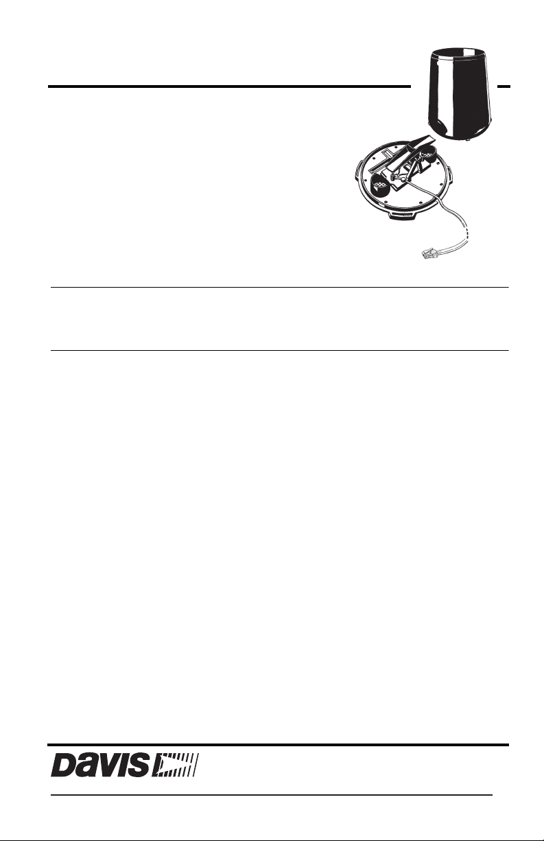
Rain Collector II
Installation manual
This instruction manual takes you step-bystep through the procedures required to
install the Rain Collector II. The Rain
Collector II is designed for use with any of
Davis’ Vantage Pro2 weather stations, including
the Anemometer/Sensor Transmitter Kit.
Note: If you are installing the Rain Collector II in a Weather Wizard or Weather Monitor, please refer
to the Rain Collector II for GroWeather, EnviroMonitor, Weather Monitor and Wizard manual
which can be found in the support section of the Davis web site. (Go to www.davisnet.com,
click Support, Weather Support, Instruction Manuals. Choose your station from the pull down
menu and scroll down to find the manual.)
Components
The Rain Collector II includes the following components. Please make sure you have all listed components before continuing.
•Rain Collector with Cable — The rain collector comes with the cone attached to the
base and has a 40’ (12m) cable.
•Four #8 x 3/4" Screws
•Debris Screen — This screen is placed into the rain collector cone to help prevent
debris from clogging the funnel hole.
•Metric Rain Adapter — This adapter adds weight to the tipping mechanism, adjusting
it to tip for every 0.2 mm of rainfall instead of every 0.01”.
Tools and Materials Needed
You may need some of the following tools and materials to install the rain collector.
•Drill with 3/32” (2 mm) drill bit
•Medium Phillips screwdriver
•3/16” (or 5 mm) wrench
•Cable clips or weather-resistant cable ties with screw holes or other means for mounting
•Bubble level
®
Davis Instruments, 3465 Diablo Avenue, Hayward, CA 94545-2778 U.S.A. • 510-732-9229 • www.davisnet.com
Page 2
Components
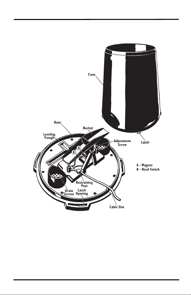
Rain Collector Internal Components
The illustration below shows the internal components of the rain collector, many of
which are referenced in this manual.
Rain Collector Internal Components
2
Page 3
Prepare the Rain Collector
Prepare the Rain Collector
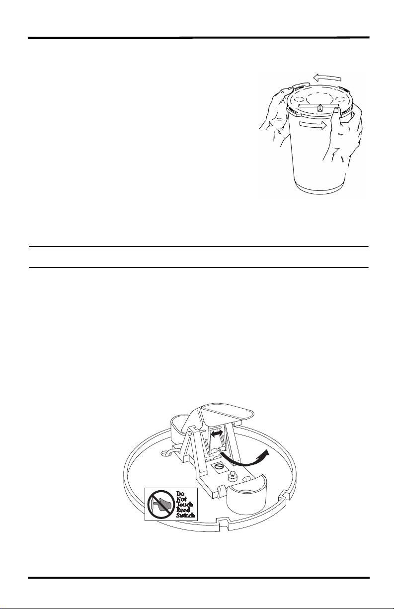
1. Turn the rain collector upside down and remove the cone from the base by rotating the base until the latches on the cone line up with the latch openings in the base then lifting the base away from the cone.
2. Carefully cut and remove the plastic tie which holds the bucket in place during shipping.
3. Insert the optional metric measurement adapter if needed. (See instructions below.)
Insert the Optional Metric Measurement Adapter
Note: The metric version, product number 7852M, comes factory calibrated to take measurements in 0.2 mm.
There is no need to install the metric measurement adapter.
If you have purchased a US version, the rain collector tipping bucket mechanism contains
a standard measurement weight magnet that takes measurements in 0.01” for every tip of
the bucket. If you would prefer readings in metric units rather than inches, you can configure your console to convert the readings to mm’s. (On the console, press either RAIN
key. Press and release 2ND, then press UNITS once.)
However, for the greatest accuracy, you may also install the included metric adapter so
that the rain collector will take measurements in 0.2 mm for each tip of the bucket.
1. Locate the standard measurement weight magnet between the arms of the tipping mechanism.
2. Open the arms slightly with one hand while pulling the magnet out with the other hand.
Remove the Cone from the
Base
Open plastic tipping mechanism arms,
pull out magnet
3
Page 4

Test the Rain Collector II
3. Separate an end cap from one side of the magnet.
4. Slide the magnet, with the exposed end of the magnet first, into the open slot of the metric measurement adapter.
5. Insert the metric measurement adapter between the arms of the tipping bucket, with solid side of the metric measurement facing up.
Open plastic arms to insert metric mea-
surement adapter, with adapter in “V”
position
Although the rain collector is now ready to take accurate metric measurements, the console does not register the rain collector measurement weight has changed. The rain measurement type must be changed on the console.
Test the Rain Collector II
Before installing the Rain Collector II, test the unit. If you are replacing a rain collector
you previously installed, make a note of the total rainfall amount displayed. You may
want to reenter this amount after you test the rain collector.
1. Open the SIM housing on the ISS. Remove the foam insert and feed the rain collector cable up through the opening. Plug the cable to the appropriate connector. (See illustration on page 6.)
2. Press the RAIN
DAY button on your console to display rainfall.
3. While watching the display on your console to see if it changes, slowly tip the bucket
until it drops to the opposite side. If the display does not change, you may be tipping
the bucket too quickly. Try again, more slowly this time.If the rainfall amount displayed on the console increases by the expected increment (either 0.01" or 0.2 mm)
each time you tip the bucket, your rain collector is working properly.
Install the Rain Collector II
Note: Climbing on your roof may be hazardous. If you are uneasy about installing your unit please have a qual-
ified professional complete the installation. Davis specifically disclaims any liability for injury or loss
resulting from the installation or use of the Rain Collector II.
Tip: When choosing a mounting surface, you may want to consider the Davis Rain
Collector Mounting Shelf, product number 7704.
4
Page 5

Install the Rain Collector II
Choosing a Location for the Rain Collector
Keep the following in mind when choosing a location for your rain collector:
•You must mount the Rain Collector so that it is level. A built-in bubble level is attached
to the base to simplify this process.
•Be sure there is an unobstructed path for water runoff from the drain screens.
•The Rain Collector II contains a magnet-operated switch which may not operate cor-
rectly if you mount the rain collector on or near any object which is attracted to a magnet.
•Exposure to winds can reduce the measured rainfall amounts. Mount the rain collector
where there are no obstructions of rainfall at low angles -- such as trees, houses, fences -
- and as low as possible out of the wind.
To install the rain collector on a sheet metal roof, insulate the unit by making a platform
out of wood. Mount the base of the rain collector at least 1"(4 cm) away from any steel
or iron surface and make sure the reed switch is at least 1" (4 cm) away from any steel or
iron objects (e.g., nails).
•Choose a location which is easily accessible for normal cleaning and is distant from
trees or other sources of heavy pollen or debris.
Installing the Rain Collector II
The following instructions assume the rain collector is being used with a Vantage Pro2 or
Vantage Pro2 Plus ISS. Refer to the user manual that came with our station for more
information.
Tip: Manuals are available online at www.davisnet.com in the Weather Support section.
1. If you have not already done so, separate the cone from the base.
2. If necessary, disconnect the rain collector cable from the Sensor Interface Module (SIM).
3. Place the base on the mounting surface and mark the location of the four holes (the base has eight to choose from) you will use to secure the base.
4. Make pilot holes using a 3/32" (2 mm) drill bit. You should make the pilot holes about 1/2" (12 mm) deep.
5. Fasten the base to the mounting surface using the #8 x 3/4” screws provided.
5
Page 6

Adjusting the Rain Collector II
6. Open the SIM housing on the ISS. Remove the foam insert and feed the rain collector cable up through the opening. Plug the cable to the appropriate connector. Replace the foam and close the SIM housing.
7. To be certain the rain collector is functioning properly after installation, retest the unit See “Test the Rain Collector II” on page 4.
8. Place the cone back onto the base by putting the latches on the cone into the latch
openings in the base and rotating the cone clockwise until the latches “lock” into
place. As you reattach the cone, make sure to run the cable to the cable slot in the base,
or the cone will not fit snugly against the base.
9. Place the debris screen, points down, into the cone. The screen prevents large bits of debris from blocking the funnel hole.
10.To prevent fraying or cutting of the cable where it is exposed to weather, it is important that you secure it so it doesn’t whip about in the wind.
Use cable clips or weather resistant cable ties to secure the cable. Place clips or ties
approximately every 3 to 5 feet (1 to 1.6 m). Do not use metal staples or a staple gun
to secure cables. Metal staples—especially when installed with a staple gun—have a
tendency to cut the cables.
Sensor
Interface
Module
(SIM)
Foam
Insert
Extending Cable Runs
If the cable length supplied with the rain collector is not long enough for your purposes,
you may extend it. The maximum length of cable is 900 feet (274 m). To extend the
cable, purchase standard 4-Conductor Extension Cables from Davis and connect them to
the existing rain collector cable.
Adjusting the Rain Collector II
The Rain Collector II (US version) is calibrated at the factory
so the bucket tips (and records rainfall) for each 0.01" (or 0.2
mm if the metric adapter has been fitted) of rain. To adjust the
calibration slightly, use a 3/16” (or 5 mm) wrench to rotate the
adjustment screws which are located underneath the bucket
(see “Rain Collector Internal Components” on page 2). The
adjustment guide embossed in the platform shows how far
you must rotate both screws in turn to effect a 1% and a 2%
6
Adjustment Guide
Page 7

Maintaining the Rain Collector II
change. Moving the screws in the positive (+) direction causes the bucket to tip more
times (i.e. give a larger count) for a given amount of water.
Note: Modify both adjustment screws by the same amount.
To check the accuracy of the rain collector, compare the Davis Rain Collector with a tube
type rain gauge. Use a rain gauge with an aperture of at least 4 inches. Any smaller and
the readings obtained may not be accurate. Place the tube type rain gauge directly next to
the Davis rain collector. Compare the totals on three storms. Based on this, develop an
average for how far off the reading are. Adjust the screws to fine tune the reading for the
next three storms if necessary.
Note: Avoid comparison to rainfall readings obtained from television, radio, newspapers, or neighbors read-
ings. Such readings are not an accurate measurement of the weather conditions in your specific surrounding. The rain collector is carefully tested at the factory to conform to the specifications listed in the
back of this manual.
Maintaining the Rain Collector II
For greatest accuracy, you should thoroughly clean the Rain Collector II at least once or
twice a year.
1. Disconnect the rain collector cable from the SIM.
2. Separate the cone from the base.
3. Use a soft damp cloth to clean pollen, dirt, and other debris from the cone, cone screens, and bucket.
4. Use a pipe cleaner to clear the funnel hole in the cone and the drain screens in the base. When all parts are clean, rinse with clear water.
5. Reattach the cone and replace the screen.
6. Reconnect the rain collector cable to the SIM.
Troubleshooting Guide
Before calling Technical Support, check the following troubleshooting guide. You may
be able to solve the problem yourself.
•Rainfall is not registering on the console or the console has a large error. Try the follow-
ing:
• Check the cable connections from the sensor to the console. Cable connections
account for a large portion of the potential problems. Connections should be firmly
seated in the jacks and plugged in straight. If you think a connection may be faulty,
try jiggling the cable while looking at the display. If a reading appears intermittently
on the display as you jiggle the cable, the connection is faulty.
• Make sure there is no magnetic, steel, or iron object near the rain collector.
• Make sure the funnel hole in the cone is clear so water can empty into the bucket.
• Make sure the bucket moves freely when tipping to both sides. The console should
show an increase in rainfall for each tip of the bucket. (If the bucket does not move
at all, check that you have cut the cable tie that holds it in place during shipping.)
• Make sure the rain collector is mounted on a level surface. Use the adjustment
screws (see “Adjusting the Rain Collector II” on page
7) to adjust the rain collector’s sensitivity, if necessary.
7
Page 8

Contacting Davis Technical Support
If you have any questions, or encounter problems installing or operating your Vantage Pro2
weather station, please contact Davis Technical Support. We’ll be glad to help.
(510) 732-7814 — Monday - Friday, 7:00 a.m. - 5:30 p.m. Pacific Time.
(510) 670-0589 — Technical Support FAX.
support@davisnet.com — E-mail to Technical Support.
info@davisnet.com — General e-mail.
www.davisnet.com — Davis Instruments web site. See the Weather Support section for
copies of user manuals, product specifications, application notes, and information on soft
ware updates. Watch for FAQs and other updates.
Specifications
Sensor Type. . . . . . . . . . . . . . . . . . . . . . Tipping bucket with magnetic reed switch
Output . . . . . . . . . . . . . . . . . . . . . . . . . . Contact closure
Attached Cable Length . . . . . . . . . . . . . 40’ (12 m)
Cable Type. . . . . . . . . . . . . . . . . . . . . . . 4-conductor, 26 AWG
Connector . . . . . . . . . . . . . . . . . . . . . . . Modular connector (RJ-11)
Recommended Max.Cable Length . . . . 900’ (270 m)
Housing Material . . . . . . . . . . . . . . . . . . UV-stabilized ABS plastic
Dimensions
Rain Collector . . . . . . . . . . . . . . . . . . . . 8.75" diameter x 9.5" high
(16.5 cm diameter x 24 cm high)
Collection Area. . . . . . . . . . . . . . . . . . . . 33.2 in2 (214 cm2)
Weight . . . . . . . . . . . . . . . . . . . . . . . . . . . . . . . 2 lbs. 3 oz. (1 kg)
Range
Daily Rainfall . . . . . . . . . . . . . . . . . . . 0.00” to 99.99” (0.0 mm to 999.8 mm)
Total Rainfall . . . . . . . . . . . . . . . . . . . 0.00” to 199.99” (0.0 mm to 6553 mm)
Accuracy . . . . . . . . . . . . . . . . . . . . . . . . For rain rates up to 2"/hr (50 mm/hr): ±4% of total
or +0.01” (0.2mm) (0.01" = one tip of the bucket),
whichever is greater. For rain rates from 2"/hr (50
mm/hr) to 4"/hr (100 mm/hr): ±5% of total or +0.01”
(0.2mm) (0.01" = one tip of the bucket), whichever
is greater.
Resolution . . . . . . . . . . . . . . . . . . . . . . . 0.01” or 0.1 mm
Update Interval. . . . . . . . . . . . . . . . . . . . 20-24 seconds
Input/Output Connections
Red . . . . . . . . . . . . . . . . . . . . . . . . . . Switch terminal
Green & Yellow . . . . . . . . . . . . . . . . . .Switch terminal
-
Product Number: 7852 Part Number: 07395.275
Rain Collector II Rev A (1/24/12)
This product complies with the essential protection requirements of the EC EMC Directive 2004/108/EC.
Copyright © 2012 Davis Instruments Corp. All rights reserved. Davis Instruments Quality Management
System is ISO 9001 certified. Information in this document is subject to change without notice.
®
3465 Diablo Avenue, Hayward, CA 94545-2778 U.S.A.
510-732-9229 • Fax: 510-732-9188
E-mail: info@davisnet.com • www.davisnet.com
 Loading...