

Datavideo PTC-200T Instruction Manual
PTC-200T
4K HDBaseT
PTZ CAMERA
Instruction Manual

2
Table of Contents
FCC Compliance Statement 4
Warnings and Precautions 4
Warranty 5
Standard Warranty 5
Three Year Warranty 6
Disposal 6
1. Product Overview 7
2. Features 8
3. Functions 9
3.1 PTZ Camera 9
3.2 HDBaseT Receiver Box 11
4. DIP Switch Settings 12
4.1 DIP Switch SW1 12
4.2 DIP Switch SW2 (IRID) 13
5. IR Remote Control 14
5.1 Remote Control Functions 14
5.2 On-Screen Menu 17
6. Instructions for Installation 25
Step 1 – DIP Switch Setting 25
Step 2 – One End of Retaining Wire 25
Step 3 – Ceiling Bracket (B) 26
Step 4 – Ceiling Bracket (A) and Camera 27

3
Step 5 – Mount Camera to Ceiling 28
Step 6 – Screw to Fix Camera 29
Step 7 – Cable Connection 29
7. Network Configuration 30
8. RMC-180 PTZ Camera Control Unit 35
8.1 Direct Connection to Camera 35
8.2 Connection to Camera via HBT-11 35
9. Firmware Update Procedure 37
10. Dimensions 38
11. Specifications 40
12. Service & Support 44
Disclaimer of Product and Services
The information offered in this instruction manual is intended as a guide only.
At all times, Datavideo Technologies will try to give correct, complete and
suitable information. However, Datavideo Technologies cannot exclude that
some information in this manual, from time to time, may not be correct or
may be incomplete. This manual may contain typing errors, omissions or
incorrect information. Datavideo Technologies always recommend that you
double check the information in this document for accuracy before making
any purchase decision or using the product. Datavideo Technologies is not
responsible for any omissions or errors, or for any subsequent loss or damage
caused by using the information contained within this manual. Further advice
on the content of this manual or on the product can be obtained by contacting
your local Datavideo Office or dealer.

4
FCC Compliance Statement
This device complies with part 15 of the FCC rules. Operation is subject to the
following two conditions:
(1) This device may not cause harmful interference, and
(2) This device must accept any interference received, including interference
that may cause undesired operation.
Warnings and Precautions
1. Read all of these warnings and save them for later reference.
2. Follow all warnings and instructions marked on this unit.
3. Unplug this unit from the wall outlet before cleaning. Do not use liquid or
aerosol cleaners. Use a damp cloth for cleaning.
4. Do not use this unit in or near water.
5. Do not place this unit on an unstable cart, stand, or table. The unit may
fall, causing serious damage.
6. Slots and openings on the cabinet top, back, and bottom are provided for
ventilation. To ensure safe and reliable operation of this unit, and to
protect it from overheating, do not block or cover these openings. Do not
place this unit on a bed, sofa, rug, or similar surface, as the ventilation
openings on the bottom of the cabinet will be blocked. This unit should
never be placed near or over a heat register or radiator. This unit should
not be placed in a built-in installation unless proper ventilation is
provided.
7. This product should only be operated from the type of power source
indicated on the marking label of the AC adapter. If you are not sure of
the type of power available, consult your Datavideo dealer or your local
power company.
8. Do not allow anything to rest on the power cord. Do not locate this unit
where the power cord will be walked on, rolled over, or otherwise
stressed.
9. If an extension cord must be used with this unit, make sure that the total
of the ampere ratings on the products plugged into the extension cord do
not exceed the extension cord’s rating.
10. Make sure that the total amperes of all the units that are plugged into a
single wall outlet do not exceed 15 amperes.
11. Never push objects of any kind into this unit through the cabinet
ventilation slots, as they may touch dangerous voltage points or short out
parts that could result in risk of fire or electric shock. Never spill liquid of
any kind onto or into this unit.
12. Except as specifically explained elsewhere in this manual, do not attempt
to service this product yourself. Opening or removing covers that are
marked “Do Not Remove” may expose you to dangerous voltage points or

5
other risks, and will void your warranty. Refer all service issues to
qualified service personnel.
13. Unplug this product from the wall outlet and refer to qualified service
personnel under the following conditions:
a. When the power cord is damaged or frayed;
b. When liquid has spilled into the unit;
c. When the product has been exposed to rain or water;
d. When the product does not operate normally under normal operating
conditions. Adjust only those controls that are covered by the
operating instructions in this manual; improper adjustment of other
controls may result in damage to the unit and may often require
extensive work by a qualified technician to restore the unit to normal
operation;
e. When the product has been dropped or the cabinet has been
damaged;
f. When the product exhibits a distinct change in performance,
indicating a need for service.
Warranty
Standard Warranty
• Datavideo equipment are guaranteed against any manufacturing defects
for one year from the date of purchase.
• The original purchase invoice or other documentary evidence should be
supplied at the time of any request for repair under warranty.
• The product warranty period beings on the purchase date. If the purchase
date is unknown, the product warranty period begins on the thirtieth day
after shipment from a Datavideo office.
• Damage caused by accident, misuse, unauthorized repairs, sand, grit or
water is not covered under warranty.
• Viruses and malware infections on the computer systems are not covered
under warranty.
• Any errors that are caused by unauthorized third-party software
installations, which are not required by our computer systems, are not
covered under warranty.
• All mail or transportation costs including insurance are at the expense of
the owner.
• All other claims of any nature are not covered.
• All accessories including headphones, cables, and batteries are not covered
under warranty.
• Warranty only valid in the country or region of purchase.
• Your statutory rights are not affected.

6
Three Year Warranty
• All Datavideo products purchased after July 1st, 2017
are qualified for a free two years extension to the
standard warranty, providing the product is registered
with Datavideo within 30 days of purchase.
• Certain parts with limited lifetime expectancy such as LCD panels, DVD
drives, Hard Drive, Solid State Drive, SD Card, USB Thumb Drive, Lighting,
Camera module, PCIe Card are covered for 1 year.
• The three-year warranty must be registered on Datavideo's official website
or with your local Datavideo office or one of its authorized distributors
within 30 days of purchase.
Disposal
For EU Customers only - WEEE Marking
This symbol on the product or on its packaging indicates
that this product must not be disposed of with your other
household waste. Instead, it is your responsibility to
dispose of your waste equipment by handing it over to a
designated collection point for the recycling of waste
electrical and electronic equipment. The separate
collection and recycling of your waste equipment at the
time of disposal will help to conserve natural resources and ensure that it is
recycled in a manner that protects human health and the environment. For
more information about where you can drop off your waste equipment for
recycling, please contact your local city office, your household waste disposal
service or the shop where you purchased the product.
CE Marking is the symbol as shown on the left of this page.
The letters "CE" are the abbreviation of French phrase
"Conformité Européene" which literally means "European
Conformity". The term initially used was "EC Mark" and it
was officially replaced by "CE Marking" in the Directive
93/68/EEC in 1993. "CE Marking" is now used in all EU official documents.

7
1. Product Overview
The PTC-200T Video Camera is a 4K UHD PTZ camera that can be mounted on
a wall, ceiling, floor, or a tabletop. The camera captures up to 4K (3,840 x
2,160, UHD) video at 2160p29.97/25 resolution, and features wide dynamic
range with backlight compensation. The camera features a motorized 12x
optical zoom capability, and its image mirror and image rotation functions
allow you to electronically adjust the image and deliver a correctly oriented
image.
50 programmable presets including pan, tilt, and zoom positions, allow the
camera to quickly move between predetermined camera positions using the
remote, or an available PTZ controller.
For multi-camera shoots, the built-in tally light can identify active camera. The
camera features a built-in IR cut filter in the image path for low light shooting,
and then returns for daytime shooting. Furthermore, the PTC-200T supports
real time position report on a per frame basis; this will be helpful to virtual
studio application. The camera supports Sony VISCA protocol for PTZ control
using RS-422 interface over the unit's RJ-45 port.
The HBT-11 HDBaseT Receiver Box is able to extend the video transmission
distance up to 100 meters. With the 48V power connected to one end of the
HBT-11 HDBaseT receiver, the HBT-11 will thus be able to power the camera
by Power over Ethernet (PoE). The HDBaseT Technology allows transmission
of HDMI video, DVIP control signals and Power over Ethernet (PoE) on just one
Ethernet cable.

8
2. Features
• HD Resolution: 1/2.3" High Definition 8.93 M Pixels progressive CMOS
sensor
• 12x optical zoom (f = 3.9 mm to 46.8 mm)
• High definition formats supported:
- 4K (3,840 x 2,160, UHD): 2160p/29.97, 2160p/25
- HD: 1080/59.94p, 1080/50p, 1080/59.94i, 1080/50i, 720/59.94p,
720/50p
• Digital Noise Reduction Function (DNR) to reduce the noise and enable
clearer image under low light conditions.
• Position coordinates report in real time per frame.
• Video Output: 3G-SDI + HDMI synchronously.
• Tally LED Design (IR Controller / RS-422 / DVIP Operation)
• Supports VISCA Protocol Keyboard
• Supports DVIP Control Protocol
• Transmits video, audio, DVIP Ethernet control, RS-422/232 and PoE to
HBT-11 Receiver Box on a single Cat.5e/6/6a/7 cable
• Transmits up to 4Kx2K video from PTZ camera to HBT-11 Receiver Box.
• Video transmission between PTZ camera and HBT-11 Receiver Box is
extended up to 100m.

9
3. Functions
In this section, the user will be introduced the individual functions of the PTZ
camera and the receiver box that comes with the product package.
3.1 PTZ Camera
Front of Camera
1
Lens
Built-in 1/2.3” 8.93M Pixel CMOS HD color
camera with white balance control,
backlight compensation settings, automatic
gain settings and etc.
2
Tally LED
Tally lamp lights up when tally signal has
been received.
3
Sensor for Remote Control
Remote controller receiver
Rear of Camera
1
DIP Switch SW2
DIP switch for IRID setting. See the DIP
Switch Settings section for details.
2
RS422 Communication Port
Connection to the RMC-180 PTZ Camera
Control Unit for remote control of the
camera via any RJ-45 cable.
See Section 8 for physical connection to
the RMC-180. For details on how to use
the RMC-180, please read the RMC-180
instruction manual.
3
3G-SDI OUT
Video signal output
4
HDMI OUT
Video signal output

10
5
HDBaseT Communication Port
Connects the camera to the HBT-11
receiver, thereby extending video
transmission up to 100m.
Note: If the camera is used as a standalone
device, this port can be used to connect the
camera directly to the PC or to a network
router via any RJ-45 cables.
See Section 7 for configuring the camera’s
network settings using the DVIP Network
Configuration Tool.
6
Power Input
DC in socket connects the supplied 12V
PSU. The connection can be secured by
screwing the outer fastening ring of the DC
In plug to the socket.
7
USB Port
The USB port is used for F/W Upgrade Only.
Insert a USB stick containing the latest
firmware files into this port.
See Section 9 for Firmware Update
Procedure.
Bottom of Camera
1
Tripod Screw Hole allows the user to
mount the camera on the tripod.
2
DIP Switch SW1
Camera settings include VISCA ID, Remote
Control Protocol, Resolution and Video
Mode Selection Method.
See the DIP Switch Settings section for
details.
3
Screw Hole
Screw holes for ceiling bracket mounting.
See Section 6 for installation instructions.

11
3.2 HDBaseT Receiver Box
Rear Panel
HDMI port for video output.
DVIP Communication Port
Connect the DVIP port to an
Ethernet switch or router, serving as
a communication port between the
network and the HBT-11 receiver.
See Section 7 for configuring the
receiver box’s network settings
using the DVIP Network
Configuration Tool.
48V DC power input supplied from
PD-6 Power Center.
Power LED Indicator
ON: Power connected
OFF: Power disconnected
Front Panel
HDBaseT Port
The communication port connects
between the PTZ camera and the
receiver box, thereby extending
video transmission up to 100m.
RS-232/RS-422 Interface
The Phoenix Terminal connects to
external RS-232/RS-422 devices such
as the RMC-180 PTZ Camera Control
Unit. See Section 8 for physical
wiring to the RMC-180.
RX: Receiver PIN (differential pair if
RS-422 is enabled)
TX: Transmitter PIN (differential pair
if RS-422 is enabled)
G: Ground PIN
DIP Switch selects the right interface.
01: RS-422 Interface
00: RS-232 Interface
12
4. DIP Switch Settings
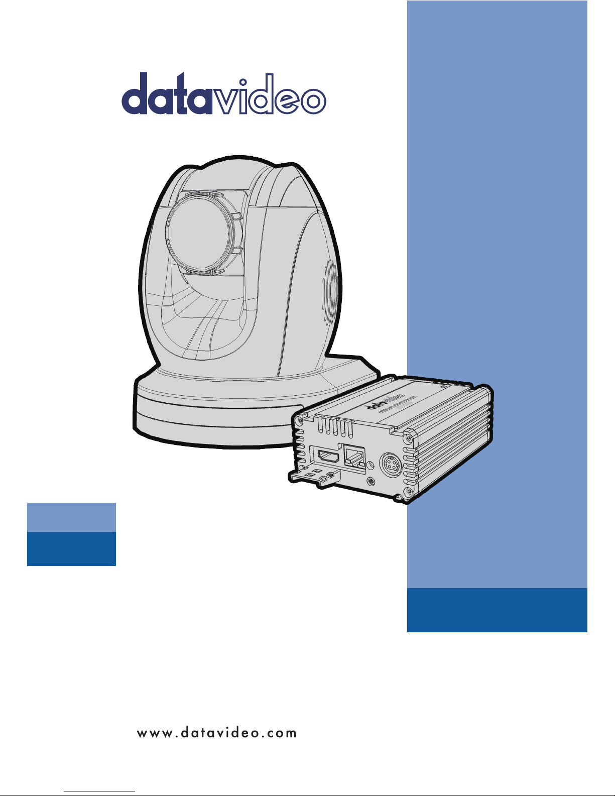
4.1 DIP Switch SW1
The DIP Switch SW1 can be found at the bottom of the camera, where the
user is allowed to set the camera’s VISCA ID, enable remote control, select the
video resolution, and configure how the video mode can be selected.
DIP SW 1/2/3
VISCA ID
ON/OFF/OFF
VISCA-ID 1
OFF/ON/OFF
VISCA-ID 2
ON/ON/OFF
VISCA-ID 3
OFF/OFF/ON
VISCA-ID 4
ON/OFF/ON
VISCA-ID 5
OFF/ON/ON
VISCA-ID 6
ON/ON/ON
VISCA-ID 7
DIP SW 4
Remote Control Protocol
ON
DVIP
OFF
RS422
DIP SW 5/6/7/8
Resolution
OFF/OFF/OFF/ON
1920 x 1080i59.94
OFF/ON/OFF/ON
1280 x 720p59.94
OFF/OFF/ON/ON
1920 x 1080p59.94
OFF/ON/ON/ON
3840 x 2160p29.97
ON/OFF/OFF/ON
1920 x 1080i50
ON/ON/OFF/ON
1280 x 720p50
ON/OFF/ON/ON
1920 x 1080p50
ON/ON/ON/ON
3840 x 2160p25
DIP SW 8
Video Mode Selection Method
ON
Video mode selectable by DIP switch only
OFF
Video mode selectable by menu
13
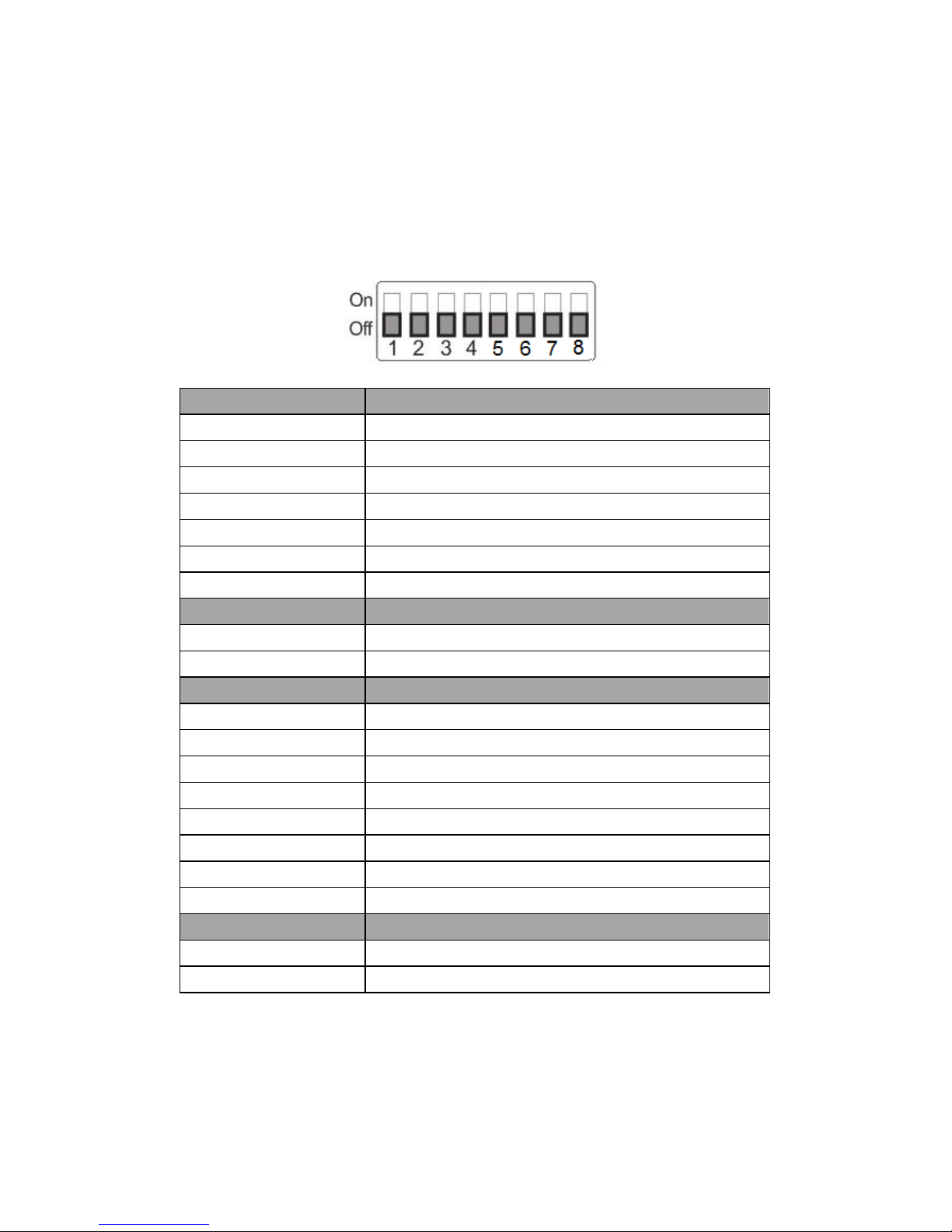
4.2 DIP Switch SW2 (IRID)
The IRID DIP Switch can be found on the rear panel of the PTC-200T camera.
This DIP switch allows the user to assign an ID number to the camera so that
the user can navigate between the cameras by pressing the CAMERA SELECT
buttons.
DIP SW 1/2
Camera Select Function (IR Remote
Control) – Camera ID Assignment
OFF/OFF
CAM1
ON/OFF
CAM2
OFF/ON
CAM3
ON/ON
CAM4
* DIP SW 3/4 should be always OFF.
14
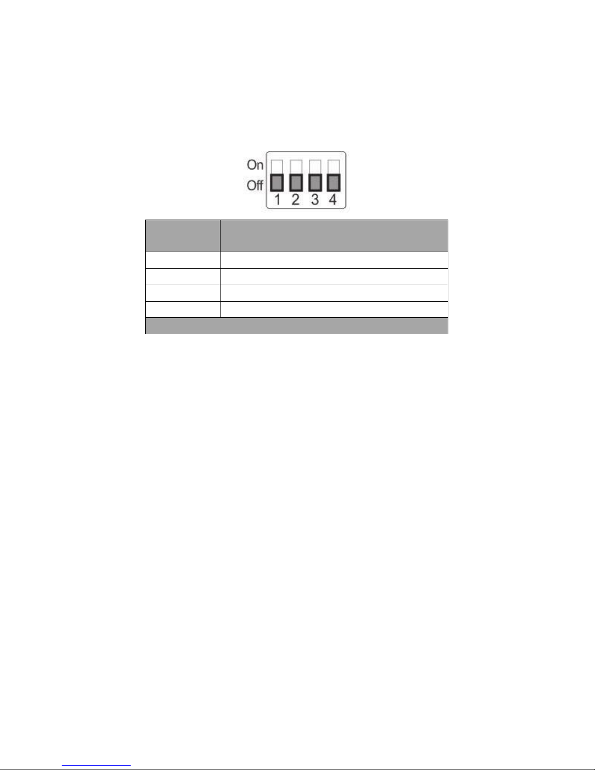
5. IR Remote Control
5.1 Remote Control Functions
No
Item
Description
1
Reset
Press RESET button to return the
camera lens to the front.
2
Group
Use the No. button & the group
button to select the group scan.
Press any of the No. buttons 1~8
and then press GROUP button.
3
Camera Select
Select CAM1-CAM4 in a multicamera environment
Assign an ID number to the
camera intended for operation by
adjusting the IRID (SW2) switch
located at the camera rear.
Press CAMERA SELECT (CAM 1~
CAM4) buttons set previously to
navigate between four cameras.
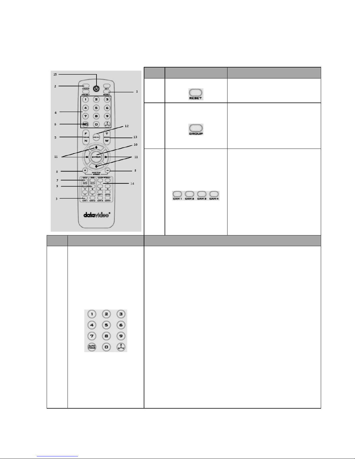
No.
Item
Description
4
Position Setting
Various combinations of settings (position, zoom, focus, gain
control and iris control) can be saved to presets.
Adjust Preset Point
Adjust position, zoom, focus, gain control and iris of the camera.
Set up Preset Point
Press any of the POSITION buttons 1~50 and then press SET
button.
Recall saved settings
Press any of the POSITION buttons 1~50 and then press PRESET
button.
Set up Group Scan mode
Press any of the POSITION buttons 1~8 and then press GROUP
button.
Return Camera Lens back to Front
Press number 0 and then press PRESET button.
 Loading...