

Page 1
HD/SD-SDI PTZ
CAMERA
PTC-150/
PTC-150W
Instruction Manual
Page 2

2
Table of Contents
FCC COMPLIANCE STATEMENT ...................................................................... 4
WARNINGS AND PRECAUTIONS .................................................................... 4
WARRANTY ................................................................................................... 6
STANDARD WARRANTY ........................................................................................ 6
THREE YEAR WARRANTY ...................................................................................... 6
DISPOSAL ...................................................................................................... 7
1. PRODUCT OVERVIEW ................................................................................ 8
2. FEATURES .................................................................................................. 9
3. LOCATION AND FUNCTION OF PARTS ...................................................... 10
4. SYSTEM DIAGRAM ................................................................................... 12
5. REMOTE CONTROL AND ON-SCREEN MENU ............................................ 13
5.1 REMOTE CONTROL FUNCTIONS ............................................................... 13
5.2 ON-SCREEN MENU .............................................................................. 16
6. INSTRUCTION FOR INSTALLATION ........................................................... 25
STEP 1 – DIP SWITCH SETTING ............................................................................ 25
STEP 2 – ONE END OF RETAINING WIRE ................................................................ 25
STEP 3 – CEILING BRACKET (B) ............................................................................ 25
STEP 4 – CEILING BRACKET (A) AND CAMERA ......................................................... 26
STEP 5 – MOUNT CAMERA TO CEILING ................................................................. 28
STEP 6 – SCREW TO FIX CAMERA ......................................................................... 29
STEP 7 – CABLE CONNECTION ............................................................................. 29
7. DIP SWITCH SETTINGS ............................................................................. 30
7.1 DIP SWITCH SW1 ............................................................................... 30
7.2 DIP SWITCH SW2 (IRID) ...................................................................... 31
8. NETWORK CONFIGURATION .................................................................... 32
9. RMC-180 PTZ CAMERA CONTROL UNIT.................................................... 37
DIRECT CONNECTION TO CAMERA ........................................................................ 37
Page 3

3
10. FIRMWARE UPDATE .............................................................................. 38
11. DIMENSIONS ......................................................................................... 39
12. SPECIFICATIONS ..................................................................................... 40
13. SERVICE & SUPPORT .............................................................................. 44
Disclaimer of Product and Services
The information offered in this instruction manual is intended as a guide only.
At all times, Datavideo Technologies will try to give correct, complete and
suitable information. However, Datavideo Technologies cannot exclude that
some information in this manual, from time to time, may not be correct or
may be incomplete. This manual may contain typing errors, omissions or
incorrect information. Datavideo Technologies always recommend that you
double check the information in this document for accuracy before making
any purchase decision or using the product. Datavideo Technologies is not
responsible for any omissions or errors, or for any subsequent loss or damage
caused by using the information contained within this manual. Further advice
on the content of this manual or on the product can be obtained by contacting
your local Datavideo Office or dealer.
Page 4

4
FCC Compliance Statement
This device complies with part 15 of the FCC rules. Operation is subject to the
following two conditions:
(1) This device may not cause harmful interference, and
(2) This device must accept any interference received, including interference
that may cause undesired operation.
Warnings and Precautions
1. Read all of these warnings and save them for later reference.
2. Follow all warnings and instructions marked on this unit.
3. Unplug this unit from the wall outlet before cleaning. Do not use liquid or
aerosol cleaners. Use a damp cloth for cleaning.
4. Do not use this unit in or near water.
5. Do not place this unit on an unstable cart, stand, or table. The unit may
fall, causing serious damage.
6. Slots and openings on the cabinet top, back, and bottom are provided for
ventilation. To ensure safe and reliable operation of this unit, and to
protect it from overheating, do not block or cover these openings. Do not
place this unit on a bed, sofa, rug, or similar surface, as the ventilation
openings on the bottom of the cabinet will be blocked. This unit should
never be placed near or over a heat register or radiator. This unit should
not be placed in a built-in installation unless proper ventilation is
provided.
7. This product should only be operated from the type of power source
indicated on the marking label of the AC adapter. If you are not sure of
the type of power available, consult your Datavideo dealer or your local
power company.
8. Do not allow anything to rest on the power cord. Do not locate this unit
where the power cord will be walked on, rolled over, or otherwise
stressed.
9. If an extension cord must be used with this unit, make sure that the total
of the ampere ratings on the products plugged into the extension cord do
not exceed the extension cord’s rating.
10. Make sure that the total amperes of all the units that are plugged into a
single wall outlet do not exceed 15 amperes.
11. Never push objects of any kind into this unit through the cabinet
ventilation slots, as they may touch dangerous voltage points or short out
parts that could result in risk of fire or electric shock. Never spill liquid of
any kind onto or into this unit.
12. Except as specifically explained elsewhere in this manual, do not attempt
to service this product yourself. Opening or removing covers that are
marked “Do Not Remove” may expose you to dangerous voltage points or
Page 5

5
other risks, and will void your warranty. Refer all service issues to
qualified service personnel.
13. Unplug this product from the wall outlet and refer to qualified service
personnel under the following conditions:
a. When the power cord is damaged or frayed;
b. When liquid has spilled into the unit;
c. When the product has been exposed to rain or water;
d. When the product does not operate normally under normal operating
conditions. Adjust only those controls that are covered by the operating
instructions in this manual; improper adjustment of other controls may
result in damage to the unit and may often require extensive work by a
qualified technician to restore the unit to normal operation;
e. When the product has been dropped or the cabinet has been damaged;
f. When the product exhibits a distinct change in performance, indicating
a need for service.
Page 6

6
Warranty
Standard Warranty
• Datavideo equipment are guaranteed against any manufacturing defects
for one year from the date of purchase.
• The original purchase invoice or other documentary evidence should be
supplied at the time of any request for repair under warranty.
• The product warranty period begins on the purchase date. If the purchase
date is unknown, the product warranty period begins on the thirtieth day
after shipment from a Datavideo office.
• All non-Datavideo manufactured products (product without Datavideo
logo) have only one year warranty from the date of purchase.
• Damage caused by accident, misuse, unauthorized repairs, sand, grit or
water is not covered under warranty.
• Viruses and malware infections on the computer systems are not covered
under warranty.
• Any errors that are caused by unauthorized third-party software
installations, which are not required by our computer systems, are not
covered under warranty.
• All mail or transportation costs including insurance are at the expense of
the owner.
• All other claims of any nature are not covered.
• All accessories including headphones, cables, and batteries are not
covered under warranty.
• Warranty only valid in the country or region of purchase.
• Your statutory rights are not affected.
Three Year Warranty
• All Datavideo products purchased after July 1st, 2017
are qualified for a free two years extension to the
standard warranty, providing the product is registered
with Datavideo within 30 days of purchase.
• Certain parts with limited lifetime expectancy such as LCD panels, DVD
drives, Hard Drive, Solid State Drive, SD Card, USB Thumb Drive, Lighting,
Camera module, PCIe Card are covered for 1 year.
• The three-year warranty must be registered on Datavideo's official
website or with your local Datavideo office or one of its authorized
distributors within 30 days of purchase.
Page 7

7
Disposal
For EU Customers only - WEEE Marking
This symbol on the product or on its packaging indicates
that this product must not be disposed of with your other
household waste. Instead, it is your responsibility to
dispose of your waste equipment by handing it over to a
designated collection point for the recycling of waste
electrical and electronic equipment. The separate collection
and recycling of your waste equipment at the time of disposal will help to
conserve natural resources and ensure that it is recycled in a manner that
protects human health and the environment. For more information about
where you can drop off your waste equipment for recycling, please contact
your local city office, your household waste disposal service or the shop where
you purchased the product.
CE Marking is the symbol as shown on the left of this page.
The letters "CE" are the abbreviation of French phrase
"Conformité Européene" which literally means "European
Conformity". The term initially used was "EC Mark" and it
was officially replaced by "CE Marking" in the Directive 93/68/EEC in 1993. "CE
Marking" is now used in all EU official documents.
Page 8

8
1. Product Overview
The PTC-150/PTC-150W HD/SD Video Camera is a PTZ camera that can be
mounted on a wall, ceiling, floor, or a tabletop, and includes an IR remote
control. The camera captures HD video at 1920 x 1080 resolution, and
features wide dynamic range with backlight compensation. The camera
features a motorized 30x optical zoom capability. The camera's image mirror
and image rotation functions allow you to electronically adjust the image and
deliver a correctly oriented image.
50 programmable presets including pan, tilt, and zoom positions, allow the
camera to quickly move between predetermined camera positions using the
remote.
For multi-camera shoots, the built-in tally light can identify when the camera
is active. The camera features a built-in IR cut filter in the image path for low
light shooting, and then returns for daytime shooting. Moreover, PTC150/PTC-150W supports real time position report on a per frame basis; this
will be helpful to virtual studio application. The camera supports Sony VISCA
protocol for PTZ control using RS-422 interface over the unit's RJ-45 port.
Page 9

9
2. Features
• HD Resolution: 1/2.8" High Definition 2.14 M Pixels progressive CMOS
sensor
• 30x optical zoom (f = 4.3 mm to 129 mm)
• High definition formats supported: 1080/59.94p, 1080/50p, 1080/59.94i,
1080/29.97p, 1080/25p, 1080/50i, 720/59.94p, 720/50p
• Standard definition formats supported: 480i, 576i
• Digital Noise Reduction Function (DNR) to reduce the noise and enable
clearer image under low light conditions.
• Position coordinates report in real time per frame.
• Video Output: HD-SDI + CVBS + HDMI synchronously.
• Tally LED Design
• Supports VISCA Protocol Keyboard
• Supports DVIP Control Protocol
Page 10
10
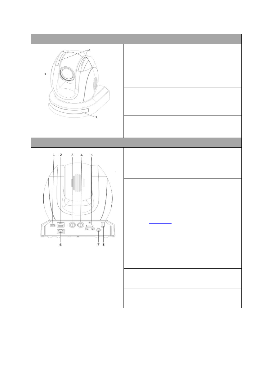
3. Location and Function of Parts
Front of Camera
1
Lens
Built-in 1/2.8” 2.14M Pixel CMOS HD color
camera with white balance control,
backlight compensation settings, automatic
gain settings and etc.
2
Tally LED
Tally lamp lights up when tally signal has
been transmitted to the tally signal box.
3
Sensor for Remote Control
Remote controller receiver
Rear of Camera
1
DIP Switch SW2
DIP switch for IRID setting. See the DIP
Switch Settings section for details.
2
RS422 Communication Port
Connection to the RMC-180 PTZ Camera
Control Unit for remote control of the
camera via any RJ-45 cable.
See Section 9 for physical connection to
the RMC-180. For details on how to use
the RMC-180, please read the RMC-180
instruction manual.
3
HD-SDI OUT
Video signal output
4
CVBS OUT
Video signal output
5
HDMI OUT
Video signal output
Page 11
11
6
HDBaseT Communication Port
Connects the camera to the receiver box,
thereby extending video transmission up to
100m.
Note: If the camera is used as a standalone
device, this port can be used to connect the
camera directly to the PC or to a network
router via any RJ-45 cables.
See Section 8 for configuring the camera’s
network settings using the DVIP Network
Configuration Tool.
7
Power Input
DC in socket connects the supplied 12V
PSU. The connection can be secured by
screwing the outer fastening ring of the DC
In plug to the socket.
8
USB Port
The USB port is used for F/W Upgrade Only.
Insert a USB stick containing the latest
firmware files into this port.
See Section 10 for Firmware Update
Procedure.
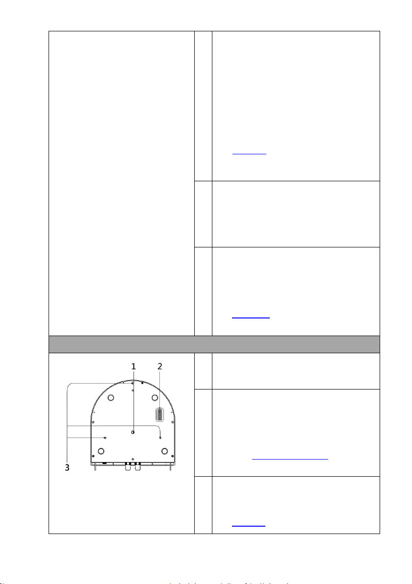
Bottom of Camera
1
Tripod Screw Hole allows the user to
mount the camera on the tripod.
2
DIP Switch SW1
Camera settings include VISCA ID, Remote
Control Protocol, Resolution and Video
Mode Selection Method.
See the DIP Switch Settings section for
details.
3
Screw Hole
Screw holes for ceiling bracket mounting.
See Section 6 for installation instructions.
Page 12
12
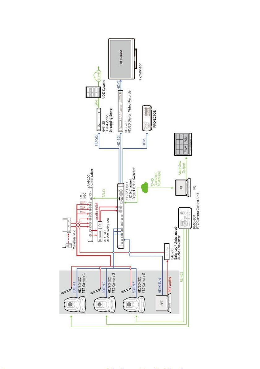
4. System Diagram
Page 13
13
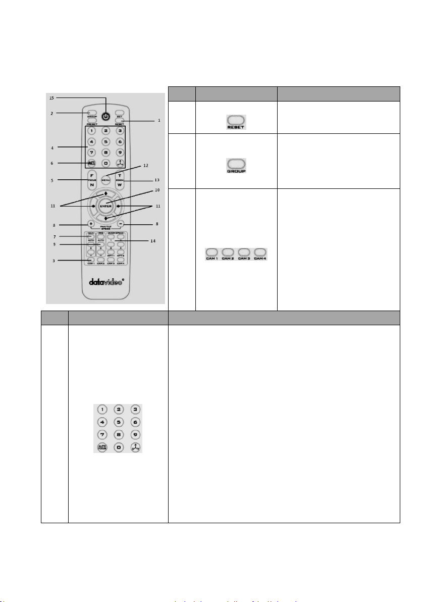
5. Remote Control and On-Screen Menu
5.1 Remote Control Functions
No
Item
Description
1
Reset
Press RESET button to return the
camera lens to the front.
2
Group
Use the No. bottom & the group
bottom to select the group scan.
Press any of the No. buttons 1~8
and then press GROUP button.
3
Camera Select
Select CAM1-CAM4 in a multicamera environment
Assign an ID number to the
camera intended for operation by
adjusting the IRID (SW2) switch
located at the rear of the camera
Press CAMERA SELECT (CAM 1~
CAM4) buttons corresponding to
the numbers set previously to
navigate between four cameras
No.
Item
Description
4
Position Setting
Various combinations of settings (position, zoom, focus, gain
control and iris control) can be saved to presets.
Adjust Preset Point
Adjust position, zoom, focus, gain control and iris of the camera.
Set up Preset Point
Press any of the POSITION buttons 1~50 and then press SET
button.
Recall saved setting
Press any of the POSITION buttons 1~50 and then press PRESET
button.
Set up Group Scan mode
Press any of the POSITION buttons 1~8 and then press GROUP
button.
Return Camera Lens back to Front
Press number 0 and then press PRESET button.
Page 14
14
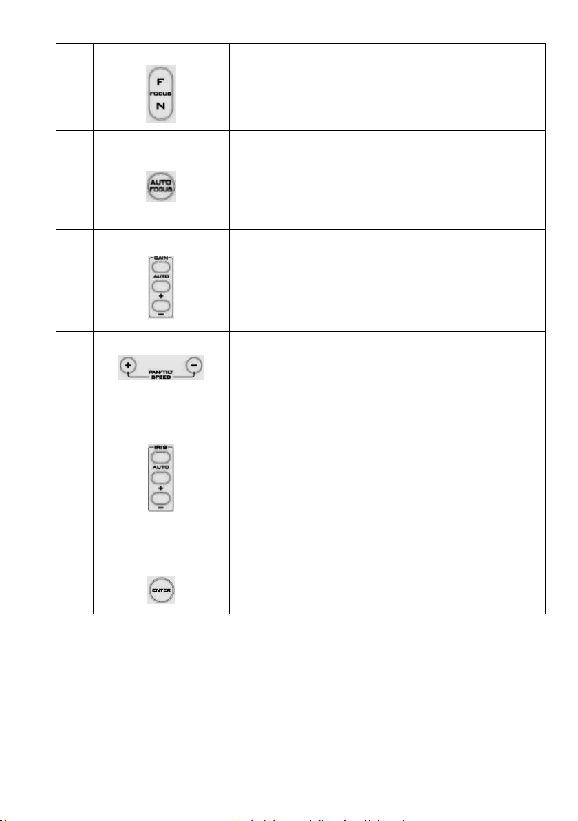
5
Focus Setup
Manually focus camera lens on a subject
Press either (F) FAR button or (N) NEAR button to manually focus
the camera lens onto the subject.
6
Auto Focus Control
Automatically focus camera lens on a subject
Press A/ FOCUS button. Camera lens will be automatically focused
on the subject such that it is positioned at the center of the screen.
Exit Sub-Menu Option
Press A/ FOCUS button to exit sub-menu option
7
Gain Control
Adjust Brightness
Press GAIN+ button to increase the brightness or GAIN- button to
decrease the brightness of the environment.
To cancel the function or return to default setup, press A/ GAIN
button.
8
P/T Speed
Adjust Pan/ Tilt Speed
Press SPEED + / - button to switch to different speed (up/down)
9
Auto Iris Control
Make the subject appear brighter
Adjust the iris opening (aperture), to control the amount of light
coming through the lens (i.e. the "exposure"). Press IRIS+ button to
enlarge the iris opening to allow more light to come in so that the
subject appears brighter and press IRIS- button to shrink the iris
opening to allow less light to come in so that the subject appears
less bright.
To cancel the function or return to default setup, press A/IRIS
button.
10
ENTER
ENTER
Menu ENTER key
Page 15

15
11
Direction Arrows
Change camera direction
Press arrow buttons to change the direction of the camera head
Stop Preset Point Auto Scan mode
Press any of the DIRECTION buttons
Select Menu Option
Press UP or DOWN button to select the menu option
Adjust P/T Speed
Press UP or DOWN button to adjust the PAN/TILT Speed
Enter Sub-Menu Option
Press ENTER button to enter sub- menu option
Adjust Setup Value
Press LEFT or RIGHT button to adjust the value
12
Enter/ Exit Camera Menu
Enter or Exit Camera Menu Option
13
Zoom In/Out Buttons
Zoom
Press either (T) TELE button to zoom in on the subject such that it
appears to be close to the camera or (W) WIDE button to zoom out
from the subject such that it appears to be far away from the
camera.
14
Zoom Speed Button
(4 speed selection)
Adjust Zoom In/Out Speed
Press this button to switch to different speed (The Highest~ The
Lowest)
15
Power Button
Switch Remote Controller ON/OFF
Page 16

16
5.2 On-Screen Menu
On-Screen Menu allows the user to change various camera settings such as
shooting conditions and the system setup. Press [Menu] on the remote
control to enter the on-screen menu as shown below.
The following table lists all the sub-options of the options on the main menu.
Main Options
Camera
Set
(Normal)
Memory
Video
Output
Remote
Control
System
Camera Set
(Advance)
Reset
P/T/Z
Escape
Sub-Options
1. Camera
Name
1. Preset
Position
1. Selection
Way
1. PAN/TILT
Reverse
1. Display
1. Camera
Name
Reset
P/T/Z
2. Mirror
2.Group-1
2. Video
Mode
2. Remote
Source
2. Set
Motor
2. Mirror
3. White
Balance
3. Group-2
3. CV Mode
3. Set RS422
3. Tally
Light
3. White
Balance
4. Focus
4. Group-3
4. Pattern
4. Set DVIP
4. Reset All
4. Focus
5. Iris
5. Group-4
5. Escape
5. Set IR
5. Update
Software
5. Iris
6. AGC
6. Group-5
6. PTZ
INFO.
output
6. Escape
6. AGC
7. Escape
7. Group-6
7. Escape
7. Fog
Correction
8. Group-7
8. Aperture
9. Group-8
9. Vivid Effect
10. Escape
10. Pedestal
Effect
11. Backlight
Correct
12. Day/Night
Mode
13. Shutter
14. Gamma
Mode
15. WD Mode
16. Escape
On-Screen MENU
1: Camera Set (Normal)
2: Memory
3: Video Output
4: Remote Control
5: System
6: Camera Set (Advance)
7: Reset P/T/Z
8: Escape
Page 17

17
Details of all options in the on-screen menu are listed in the table below.
First Level
Main Options
Second Level
Sub-Options
Third Level
Parameters
Fourth Level
Parameters
Sub-Option
Descriptions
1. Camera Set
(Normal)
1. Camera Name
NAME
DISPLAY SW
ON/OFF
POSITION
LOWER LEFT
UPPER RIGHT
ESCAPE
2. Mirror
H+V
V H OFF
3. White
Balance
MODE
AWB(AUTO)
AWC (ONE PUSH)
MWB (MANUAL)
3200K (INDOOR)
6500K (OUTDOOR)
4200K (FLUO)
SMART ATW
OFF SMART1/2/3
MWB RED COMPONENT
0~128~255
MWB BLUE COMPONENT
0~128~255
ESCAPE
4. Focus
FOCUS MODE
AUTO MANUAL
AF SENSITIVITY
LOW NORMAL
FOCUS SPEED
1~4
ESCAPE
5. Iris
IRIS MODE
AUTO IRIS
MANUAL
MANUAL IRIS LEVEL
F1.6 F2.0 F2.4 F2.8 F3.4 F4
F4.8
F5.6 F6.8
F8
F9.6 F11 F14 CLOSE
ESCAPE
6. AGC
DAY (COLOR) AGC
AGC MODE
OFF
ON
MANUAL GAIN
0 dB ~ GAIN
LIMIT
GAIN LIMIT
9 dB
12 dB
15 dB
Page 18

18
18 dB
21 dB
24 dB
27 dB
30 dB
33 dB
36 dB
39 dB
ESCAPE
DNR
DNR (AT AGC ON)
ON
OFF
DNR LEVEL
0 1 2 3 4
5
ESCAPE
ESCAPE
7. Escape
2. Memory
1. Preset
Position
1-50
P T Z 51
ESCAPE
2. Group – 1
1-16
PRESET NO.
1~50
ITEM ON/OFF
ON/OFF
SPEED LIMIT
1~18
WAITING TIME
0~180
NEXT POSITION
NEXT TIME
RETURN
GROUP – 1
GROUP – 2
GROUP – 3
GROUP – 4
GROUP – 5
GROUP – 6
GROUP – 7
GROUP – 8
ESCAPE
17. ESCAPE
3. Group – 2
1-16
PRESET NO.
1~50
ITEM ON/OFF
ON/OFF
SPEED LIMIT
1~18
WAITING TIME
0~180
NEXT POSITION
NEXT TIME
RETURN
GROUP – 1
GROUP – 2
GROUP – 3
GROUP – 4
GROUP – 5
GROUP – 6
GROUP – 7
GROUP – 8
ESCAPE
17. ESCAPE
4. Group – 3
1-16
PRESET NO.
1~50
Page 19

19
ITEM ON/OFF
ON/OFF
SPEED LIMIT
1~18
WAITING TIME
0~180
NEXT POSITION
NEXT TIME
RETURN
GROUP – 1
GROUP – 2
GROUP – 3
GROUP – 4
GROUP – 5
GROUP – 6
GROUP – 7
GROUP – 8
ESCAPE
17. ESCAPE
5. Group – 4
1-16
PRESET NO.
1~50
ITEM ON/OFF
ON/OFF
SPEED LIMIT
1~18
WAITING TIME
0~180
NEXT POSITION
NEXT TIME
RETURN
GROUP – 1
GROUP – 2
GROUP – 3
GROUP – 4
GROUP – 5
GROUP – 6
GROUP – 7
GROUP – 8
ESCAPE
17. ESCAPE
6. Group – 5
1-16
PRESET NO.
1~50
ITEM ON/OFF
ON/OFF
SPEED LIMIT
1~18
WAITING TIME
0~180
NEXT POSITION
NEXT TIME
RETURN
GROUP – 1
GROUP – 2
GROUP – 3
GROUP – 4
GROUP – 5
GROUP – 6
GROUP – 7
GROUP – 8
ESCAPE
17. ESCAPE
7. Group – 6
1-16
PRESET NO.
1~50
ITEM ON/OFF
ON/OFF
SPEED LIMIT
1~18
WAITING TIME
0~180
NEXT POSITION
NEXT TIME
RETURN
GROUP – 1
GROUP – 2
GROUP – 3
GROUP – 4
Page 20

20
GROUP – 5
GROUP – 6
GROUP – 7
GROUP – 8
ESCAPE
17. ESCAPE
8. Group – 7
1-16
PRESET NO.
1~50
ITEM ON/OFF
ON/OFF
SPEED LIMIT
1~18
WAITING TIME
0~180
NEXT POSITION
NEXT TIME
RETURN
GROUP – 1
GROUP – 2
GROUP – 3
GROUP – 4
GROUP – 5
GROUP – 6
GROUP – 7
GROUP – 8
ESCAPE
17. ESCAPE
9. Group – 8
1-16
PRESET NO.
1~50
ITEM ON/OFF
ON/OFF
SPEED LIMIT
1~18
WAITING TIME
0~180
NEXT POSITION
NEXT TIME
RETURN
GROUP – 1
GROUP – 2
GROUP – 3
GROUP – 4
GROUP – 5
GROUP – 6
GROUP – 7
GROUP – 8
ESCAPE
17. ESCAPE
10. Escape
3. Video
Output
1. Selection Way
BY MENU
BY SWITCH
2. Video Mode
1080i60
1080i50
720p60
720p50
1080p30
1080p25
1080p60
1080p50
3. CV Mode
16:9
4:3
4. Pattern
OFF
COLOR BAR
5. Escape
4. Remote
1. PAN/TILT
Reverse
OFF P
Page 21

21
Control
T
P+T
2. Remote
Source
RS-422, SW
(Configurable using
bottom DIP switch ONLY)
3. Set RS-422
CAMERA ID MODE
BY MENU
BY SWITCH
CAMERA ID
1~7
RS-422 BAUD RATE
9600 19200 38400 115200
ESCAPE
4. Set DVIP
DVIP BAUD RATE
9600 19200
38400
57600
115200
ESCAPE
5. Set IR
IR GROUP ID
(Configurable using rear
DIP switch ONLY)
CAM1~4
ESCAPE
6. PTZ INFO.
Output
ON/OFF
7. Escape
5. System
1. Display
P/T/Z OSD
PAN OSD
ON/OFF
TILT OSD
ON/OFF
ZOOM OSD
ON/OFF
ESCAPE
DEBUG OSD
DEBUG IR OSD
ON/OFF
DEBUG CAM. OSD
ON/OFF
DEBUG RS-422 OSD
ON/OFF
DEBUG DVIP OSD
ON/OFF
DEBUG M_CTL OSD
ON/OFF
DEBUG REG OSD
ON/OFF
DEBUG FRAME NO
ON/OFF
PWR ON CAM TEST
ON/OFF
ESCAPE
2. Set Motor
PAN torque ADJ
LOW +1~+5
TILT torque ADJ
LOW +1~+5
PAN offset ADJ
+5.4
+4.5
+3.6 +2.7 +1.8 +0.9 0.0 -0.9
-1.8
-2.7 -3.6 -4.5 -5.4 TILT offset ADJ
+6.3
Page 22

22
+5.4 +4.5
+3.6
+2.7 +1.8 +0.9 0.0 -0.9 -1.8 -2.7
-3.6
-4.5 -5.4 -6.3 ESCAPE
3. Tally Light
RED/GREEN
GREEN
RED
OFF
4. Reset All
YES/NO
5. Update
Software
SW VERSION
ESCAPE
MB CPU
V01.17i
MB FPGA
V017 MCTL CPU
V00.42
UPDATE ALL
YES/NO
ESCAPE
6. Escape
6. Camera Set
(ADVANCE)
1. Camera Name
NAME
DISPLAY SW
ON/OFF
POSITION
UPPER LEFT
LOWER LEFT
UPPER RIGHT
LOWER RIGHT
ESCAPE
2. Mirror
H+V V H
OFF
3. White
Balance
MODE
AWB (AUTO)
AWC (ONE PUSH)
MWB (MANUAL)
3200K (INDOOR)
6500K (OUTDOOR)
4200K (FLUO)
SMART ATW
(Enabled in AWB (AUTO)
mode)
OFF
SMART1~3
MWB RED COMPONENT
0~128~255
MWB BLUE COMPONENT
0~128~255
ESCAPE
4. Focus
FOCUS MODE
AUTO MANUAL
AF SENSITIVITY
LOW
NORMAL
Page 23

23
FOCUS SPEED
1 2
3
4 ESCAPE
5. Iris
IRIS MODE
AUTO MANUAL
Manual IRIS LEVEL
F1.6 F2.0 F2.4
F2.8
F3.4 F4 F4.8 F5.6 F6.8
F8
F9.6
F11
F14 CLOSE
ESCAPE
6. AGC
DAY (COLOR) AGC
AGC MODE
ON/OFF
MANUAL GAIN
0dB~GAIN
LIMIT
GAIN LIMIT
9 dB
12 dB
15 dB
18 dB
21 dB
24 dB
27 dB
30 dB
33 dB
36 dB
39 dB
ESCAPE
DNR
DNR(AT AGC ON)
ON
OFF
DNR LEVEL
0 1 2
3 4 5
ESCAPE
7. Fog
Correction
FOG CORRECTION
OFF/ON
ESCAPE
8. Aperture
0~15
9. Vivid Effect
0~14
10. Pedestal
Effect
0~14
11. Backlight
Correction
OFF/ON
(This option is enabled
Page 24

24
after AGC is turned on)
12. Day/Night
Mode
B/W
COLOR
13. Shutter
SHUTTER SPEED
NORMAL
1/100 1/125
1/250
1/500 1/1000
ESCAPE
14. Gamma
Mode
STANDARD
MODE1 (WD OFF)
MODE2 (WD OFF)
MODE3 (WD OFF)
MODE4 (WD OFF)
15. WD Mode
ON/OFF
(This option is enabled
after AGC is turned on)
16. Escape
7. Reset P/T/Z
Reset P/T/Z
YES/NO
8. Escape
Page 25

25
6. Instruction for installation
Step 1 – DIP Switch Setting
Set the Mirror option to H+V mode.
Step 2 – One End of Retaining Wire
Attach the retaining wire to the junction box mounted on the ceiling by
screwing one end of the retaining wire into a screw hole in the junction box
with a screw (not supplied) as shown in the diagram below.
Step 3 – Ceiling Bracket (B)
• Again, as illustrated in the diagram below, screw a ceiling bracket (B)
into the junction box mounted on the ceiling.
• Make sure the screw holes of the ceiling bracket (B) are aligned with
the holes on the junction box.
Page 26

26
Step 4 – Ceiling Bracket (A) and Camera
• Screw ceiling bracket (A) into the bottom of the camera using three
screws.
• Position the screws as shown in the diagram below.
• Align the screw holes on the bottom of the camera with those in the
ceiling bracket.
• Insert the screws into the corresponding screw holes in the numbered
order.
• The other end of the retaining wire is screwed into the screw hole #3.
• Securely tighten all three screws.
Page 27

27
Page 28

28
Step 5 – Mount Camera to Ceiling
Page 29

29
Step 6 – Screw to Fix Camera
Fix the camera by screwing three screws into the corresponding screw holes
as shown in the diagram below.
Step 7 – Cable Connection
Connect the cables to the connectors located on the rear of the camera.
Page 30

30
7. DIP Switch Settings
7.1 DIP Switch SW1
The DIP Switch SW1 can be found at the bottom of the camera, where the
user is allowed to set the camera’s VISCA ID, enable remote control, select the
video resolution, and configure how the video mode can be selected.
DIP SW 1/2/3
VISCA ID
(1,2,3) = (ON,OFF,OFF)
VISCA-ID 1
(1,2,3) = (OFF,ON ,OFF)
VISCA-ID 2
(1,2,3) = (ON ,ON ,OFF)
VISCA-ID 3
(1,2,3) = (OFF,OFF,ON)
VISCA-ID 4
(1,2,3) = (ON ,OFF,ON)
VISCA-ID 5
(1,2,3) = (OFF,ON ,ON)
VISCA-ID 6
(1,2,3) = (ON ,ON ,ON)
VISCA-ID 7
DIP SW 4
Remote Control Protocol
ON
DVIP
OFF
RS-422
DIP SW 5/6/7
Resolution
(5,6,7) = (OFF,OFF,OFF)
1920x1080i60
(5,6,7) = (ON,OFF,OFF)
1920x1080i50
(5,6,7) = (OFF,ON,OFF)
1280x720p60
(5,6,7) = (ON,ON,OFF)
1280x720p50
(5,6,7) = (OFF,OFF,ON)
1920x1080p30
(5,6,7) = (ON,OFF,ON)
1920x1080p25
(5,6,7) = (OFF,ON,ON)
1920x1080p60
(5,6,7) = (ON,ON,ON)
1920x1080p50
DIP SW 8
Video Mode Selection Method
ON
Video mode selectable by DIP switch only
OFF
Video mode selectable by menu
Page 31

31
7.2 DIP Switch SW2 (IRID)
The IRID DIP Switch can be found on the rear panel of the PTC-150/PTC-150W
camera. This DIP switch allows the user to assign an ID number to the camera
so that the user can navigate between the cameras by pressing the CAMERA
SELECT buttons.
DIP SW 1/2
Camera Select Function (IR Remote
Control) – Camera ID Assignment
(1,2) = (OFF,OFF)
CAM1 (IR)
(1,2) = (ON,OFF)
CAM2 (IR)
(1,2) = (OFF,ON)
CAM3 (IR)
(1,2) = (ON,ON)
CAM4 (IR)
* DIP SW 3/4 should be always OFF.
Page 32

32
8. Network Configuration
The DVIP Configuration Tool allows the user to configure network settings of
the PTC series cameras on the PC. The DVIP Configuration Tool can be
downloaded from the product page.
The PTC series cameras usually have a static IP address of 192.168.100.XXX.
The unit can be directly connected to a Windows-based computer using an RJ45 Ethernet cable. The following setup procedure outlined below should allow
you to initially configure the unit before moving it to an existing DHCP / LAN
network.
Note: All devices should be connected to the same network domain.
1. First connect the DVIP port of the PTC-150/PTC-150W PTZ camera to a
Windows computer using an RJ-45 Ethernet cable.
Note: You do not need to manually assign an IP address to the PC but
make sure the right interface card is selected at Step 11.
2. Install the DVIP Configuration Tool by double clicking the
executable file already downloaded to your computer.
3. Locate the DIP switch at the bottom of the PTC series camera.
4. Set DIP Switch positions 1 and 4 to ON.
5. Plug in the power cord into the PTC series camera and connect it to a
monitor via the HDMI interface.
6. Open the main menu by pressing the menu button on the IR remote
control and select option 4 “Remote Control.”
[MAIN MENU]
1:
CAMERA SET (NORMAL)
2:
MEMORY
3:
VIDEO OUTPUT
4:
REMOTE CONTROL
Page 33

33
5:
SYSTEM
6:
CAMERA SET (ADVANCE)
7:
RESET P/T/Z
8:
ESCAPE
7. Select “SET DVIP.”
[REMOTE CONTROL]
1:
PAN/TILT REVERSE: P+T
2:
REMOTE SOURCE: DVIP, SW
3:
SET RS422
4:
SET DVIP
5:
SET IR
6:
PTZ INFO. OUTPUT: OFF
7:
ESCAPE
8. Set DVIP baud rate to 115200.
[SET DVIP]
1:
DVIP BAUDRATE: 115200
2:
ESCAPE
9. Connect your PC directly to the DVIP port on the PTC series camera or if in
a multiple DVIP device environment, connect all devices to an Ethernet
router. Please note that the router and the connected devices should be
in the same IP range.
10. On the PC, open the DVIP Configuration Tool by double
clicking “DVIP_Net_Conf.exe.” The DVIP Configuration Tool
can be obtained from Datavideo local distributors or
downloaded from the product page.
11. After the DVIP Configuration Tool is opened, select your network
interface card and click the “OK” button.
Note: Make sure you select the card that is on the same network as the
camera or else the DVIP Configuration Tool will not be able to find the
connected DVIP devices.
Page 34

34
12. On the DVIP Device List, you will then be able to see the Device Name,
MAC address and IP address of the connected device.
13. After the network setting (Static or DHCP) and the host name are properly
configured, click the “Save” button to write the new information into the
device.
14. Right after the “Save” button is clicked, you will be able to see a prompt
message at the top right corner to request for a device reboot for the new
settings to become effective.
Page 35

35
15. Reboot the device to apply the new settings.
In addition to configuring network settings of the connected DVIP devices, the
DVIP configuration tool also allows you to search for DVIP devices, clear the
device list, switch to other interface cards and change the interface language.
Each individual function is described below.
• Device Search
On the tool bar, the user can click the search icon to search for all DVIP
devices.
• Clearing Device List
On the tool bar, the user is allowed to clear the device list by clicking the
“Device List Clear” button.
Page 36

36
• Switch to Other Network Interfaces
To select other network interface cards, click Network Network Card
• Language Selection
On the tool bar, select a language: Traditional Chinese, Simplified Chinese or
English
Page 37

37
9. RMC-180 PTZ Camera Control Unit
The RMC-180 PTZ Camera Controller is designed to control up to 4 Datavideo
Pan Tilt Zoom (PTZ) cameras such as the PTC-150/PTC-150W.
The four RJ-45 ports provided on the RMC-180 rear serve to connect PTZ
cameras, thus allowing the user to use any RJ-45 cable to connect the RMC180 to the RS-422 port located on the PTZ camera’s rear panel. The
communication protocol is VISCA.
Note: Before connecting the camera to these channel ports, please set bit 4
of the camera DIP switch located at the bottom to OFF.
Direct Connection to Camera
To use the RMC-180 PTZ Camera Control Unit to directly control the PTC150/PTC-150W camera, connect the RS-422 port on the camera’s rear panel
to the RJ-45 port of the RMC-180 using any RJ-45 cable. The RS-422 wiring
scheme is shown below.
RMC-180 Controller
(RJ-45 Port)
PTC-150/PTC-150W Camera
(RS-422 Port)
GND 1 White/Orange
White/Orange
1
GND
NC 2 Orange
Orange 2 NC
TX- 3 White/Green
White/Green
3
RX-
RX-
4
Blue
Blue 4 TX-
RX+ 5 White/Blue
White/Blue
5
TX+
TX+
6
Green
Green 6 RX+
NC 7 White/Brown
White/Brown
7
NC
NC
8
Brown
Brown 8 NC
GND
Page 38

38
10. Firmware Update
1) Copy three image files, p150mcpu.bin, P150FPGA.bin and p150mctl.bin,
into the root directory of a USB hard drive (<16 GB) and insert it into the
USB port of PTC-150/PTC-150W (You may also use USB extension cord).
2) Open the operation menu of IR remote controller (select from CAM 1-4;
default is CAM1)
3) Main Menu
=> 5: SYSYEM
=> 4: UPDATE SOFTWARE
=> 5: UPDATE ALL
=>YES
=> ENTER
4) Wait for another five minutes until the following lines appear on the
screen
- Updated Mot-BD=>OK.
- Updated FPGA =>OK.
- Updated MCPU =>OK
The OSD will flash “Write OK/Power ON Again” alternately; it takes
approximately 5-7 minutes to complete the update.
5) Turn off the device by unplugging the power cord and plug the power
cord back into the socket to turn on the device again.
6) FW Update is complete.
Page 39

39
11. Dimensions
Unit: mm
Page 40

40
12. Specifications
Video
Image Pickup Element
1/2.8” type progressive scan CMOS sensor
Effective Picture Elements
Approx. 2.14 Mega pixels
Resolution
HD / FHD / SD (CVBS only)
Signal System
HDMI & SDI: 1080p 59.94/50/29.97/25
1080i 59.94/50
720p 59.94/50
CVBS: 480i, 576i
S/N Ratio
50 dB
Min. Illumination
Color : 0.4 lx (F1.6, 1/30 sec, 50IRE, Gain: High)
B/W : 0.03 lx (F1.6, 1/30 sec, 50IRE, Gain: High)
Electric Shutter
1/25 (1/30), 1/50 (1/60), 1/120 (1/100), 1/250,
1/500, 1/1000 sec
Gamma Control
Off / Normal / Standard Mode 1-4
Iris Control
Auto / Manual
Digital Noise Reductions
0 - 5
On-Screen Display (OSD)
English
White Balance
AWB / MWB / One push WB / Outdoor / Indoor /
Fluorescent
AGC / Gain Control
Auto / Manual (0 to 39 step)
Max. Gain Limit (9 to 39 step)
Zoom Ratio
30x Optical Zoom
Mirror
OFF / Horizontal / Vertical / H+V
Camera Title (OSD)
ON / OFF
Color Bar
On / Off (Full Bar)
Focus Mode
Auto / Manual
Day & Night (IR)
Auto / Color / BW
Pan / Tilt / Zoom
Pan/Tilt Range
Pan: 270° , Tilt: +90° to -20°
Pan/Tilt Speed
Manual: 1~150°/Sec
Swing: 1~150°/Sec
Initialization Time
30 sec
Coordinate Report
P, T, Z (While Panning , Tilting and Zooming ) by
frame
Page 41

41
Lens
Lens Type
30x Optical Zoom
Focal Length
F=4.3 mm (WIDE) to 129 mm (TELE)
F1.6 to F4.7
Angle of View
(Horizontal)
Approx. 63.7 degrees (WIDE END) / 2.3 degrees
(TELE END)
Filter
M52.0x0.75 Thread with UV Protection
RoHS
Compliant
Video Output
Video Output
HDMI (V1.3) x 1
HD-SD-SDI x 1
CVBS x 1
Video Format Output
1 Vp-p / 75 Ohms
Control
Protocol
VISCA / DVIP
Remote Control
RS-422 & DVIP by RJ-45 interface
Remote Controller
RMC-180
F/W Update
USB 2.0
IR Control
One IR controller
Others
Moving Noise while Tilt
<=25dB
Moving Noise while Pan
<=25dB
Operating Temperature
0°C ~ 50°C
Storage Temperature
- 10°C ~ 60°C
Operating Humidity:
10 % to 80 % (no condensation)
Certifications
CE / FCC Class A
Weight
2.76 Kg (Camera Device Only)
Accessories
IR Remote Controller
Mounting Bracket (for table or ceiling)
Mounting Bracket (for main unit)
Mounting Screws
DC 12V Power Adapter
Power Cord
Page 42

42
Note
Page 43

43
Note
Page 44

Service & Support
DATAVIDEO WORLDWIDE OFFICES
It is our goal to make owning and using Datavideo products a satisfying
experience. Our support sta is available to assist you to set up and operate
your system. Contact your local oce for specic support requests. Plus,
please visit www.datavideo.com to access our FAQ section.
China Shanghai
Datavideo Technologies China Co
601,Building 10,No.1228,
Rd.Jiangchang,
Jingan District,Shanghai
Tel: +86 21-5603 6599
Fax:+8 6 21-5603 6770
E-mail:service@dat avideo.cn
China Beijing
Datavideo Technologies China Co
No. 812, Building B, Wankai Center,
No.316, Wan Feng Road, Fengtai District,
Beijing, China
Tel: +86 10-8586 9034
Fax:+86 10-8586 9074
E-mail:service@dat avideo.cn
China Chengdu
Datavideo Technologies China Co
B-823,Meinian square,No.1388,
Middle of Tianfu Avenue,Gaoxin District,
Chengdu,Sichuan
Tel: +86 28-8613 7786
Fax:+86 28-8513 6486
E-mail:service@dat avideo.cn
China Fuzhou
Datavideo Technologies China Co
A1-2318-19 Room,No.8, Aojiang Road,
Taijiang District,Fuzhou,Fujian,China
Tel: 0591-83211756,0591-83210187
Fax:0591-83211262
E-mail:service@dat avideo.cn
China Jinan
Datavideo Technologies China Co
902, No. 1 business building,
Xiangtai Square, No. 129,
Yingxiongshan Road, Shizhong District,
Jinan City, Shandong Province, China
Tel: +86 531-8607 8813
E-mail:service@dat avideo.cn
Please visit our website for latest manual update.
www.datavideo.com/product/PTC-150
www.datavideo.com/product/PTC-150W
Hong Kong
Datavideo Hong Kong Ltd
G/F.,26 Cross Lane
Wanchai, Hong Kong
Tel: +852-2833-1981
Fax:+852-2833-9916
E-mail:inf o@datavideo.com.hk
India Noida
Datavideo India Noida
A-132, Sec-63,Noida-201307,
India
Tel: +91-0120-2427337
Fax:+91-0120-2427338
E-mail: sales@datavideo.in
India Kochi
Datavideo India Kochi
2nd Floor- North Wing, Govardhan Building,
Opp. NCC Group Headquaters, Chittoor Road,
Cochin- 682035
Tel: +91 4844-025336
Fax:+91 4844-047696
Netherlands
Datav ideo Technologies Europe B V
Floridadreef 106
3565 AM Utrec ht,
The Net herlands
Tel: +31-30-261-96-5 6
Fax :+31-30-261-96-5 7
E-mail:inf o@datavideo. nl
Singapore
Datavideo Visual Technology(S) Pte Ltd
No. 178 Paya Lebar Road #06-07
Singapore 409030
Tel: +65-6749 6866
Fax:+65-6749 3266
E-mail:info@datavideovirtualset.com
Singapore
Datav ideo Technologies (S ) PTE Ltd
No. 178 Paya Lebar Road #06-03
Singapore 409030
Tel: +65-6749 6866
Fax:+65-6749 3266
E-mail:sales @datavideo.sg
Taiwan
Datavideo Technologies Co. Ltd
10F. No. 176, Jian 1st Rd.,Chung Ho
District, New Taipei City 235, Taiwan
Tel: +886-2-8227-2888
Fax:+886-2-8227-2777
E-mail:service@datavideo.com.tw
United States
Datavideo Corporation
7048 Elmer Avenue.
Whittier, CA 90602,
U.S.A.
Tel: +1-562-696 2324
Fax:+1-562-698 6930
E-mail:sales@datavideo.comE-mail: sales@datavideo.in
United Kingdom
Datav ideo UK Limite d
Brookfield House, Brookfield Industrial
Estate, Peakdale Road, Glossop,
Derbyshire, SK13 6LQ
Tel: +44-1457 851 000
Fax :+44-1457 850 964
E-mail:sales @datavideo.co.u k
France
Datavideo France s.a.r.l.
Cité Descartes 1, rue Albert Einstein
Champs sur Marne 774477 –
Marne la Vallée cedex 2
Tel: +33-1-60370246
Fax :+33-1-60376732
E-mail:info@datavideo.fr
All the trademarks are the properties of their respective owners. Datavideo Technologies
Co., Ltd. All rights reserved 2018
Jan-02.2018
Version : E3
 Loading...