

V.34 Modem for Data & Fax
XE2814
08-27-96
Description
Xecom's XE2814 combines high-speed V.34
data and Group III send/receive fax in a
compact component.
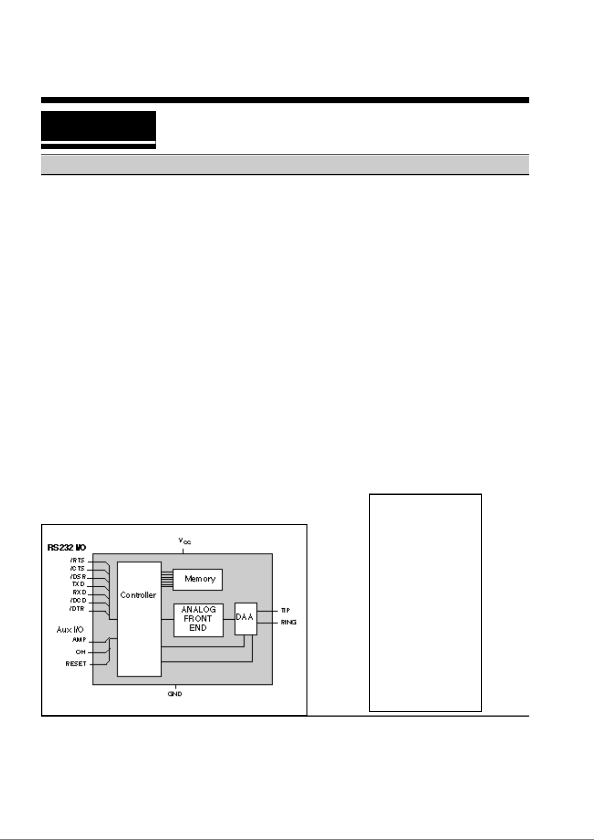
The XE2814 is not just a modem chip but a
complete modem including the telephone
interface. It includes user transferable FCC
Part 68 registration and can connect directly
to the telephone line through an RJ11 jack.
The modem connects to the host through a
TTL level serial interface.
Xecom designed the XE2814 specifically
for commercial and industrial systems with a
need for high-speed communications and
minimal space.
XE2814
PIN CONFIGURATION
Features
• Small Size; 2.75 " x 1.38" x 0.42"
• Modem control with "AT" commands
• Class 1 and Class 2 fax commands
• Data transfer up to 28,800 bps
• Send and receive fax to 14,400 bps
• MNP and V.42 Error Control
• MNP5 Data Compression to 57,600 bps
• MNP10 Error Control for Cellular links.
• V.42bis Data Compression to 115,200 bps
• Low power, single +5V supply
Operating Power 900 mW (Typ.)
Sleep mode: 50 mW (Typ.)
• NVRAM for modem configuration storage
xecom
1 40
2 39
3 38
4 37
5 36
6 35
7 34
8 33
9 32
10 31
11 30
12 29
13 28
14 27
15
16
18
22
20 21
NC
NC
RXD
NC
NC
NC
NC
NC
/DTR
NC
/CTS
NC
TXD
/RTS
NC
/RI
TIP
RING
VCC
/DSR
/DCD
NC
RESET
NC
NC
NC
NC
NC
OH
NC
NC
NC
AMP
GND
Block Diagram
2/XECOM XE2814
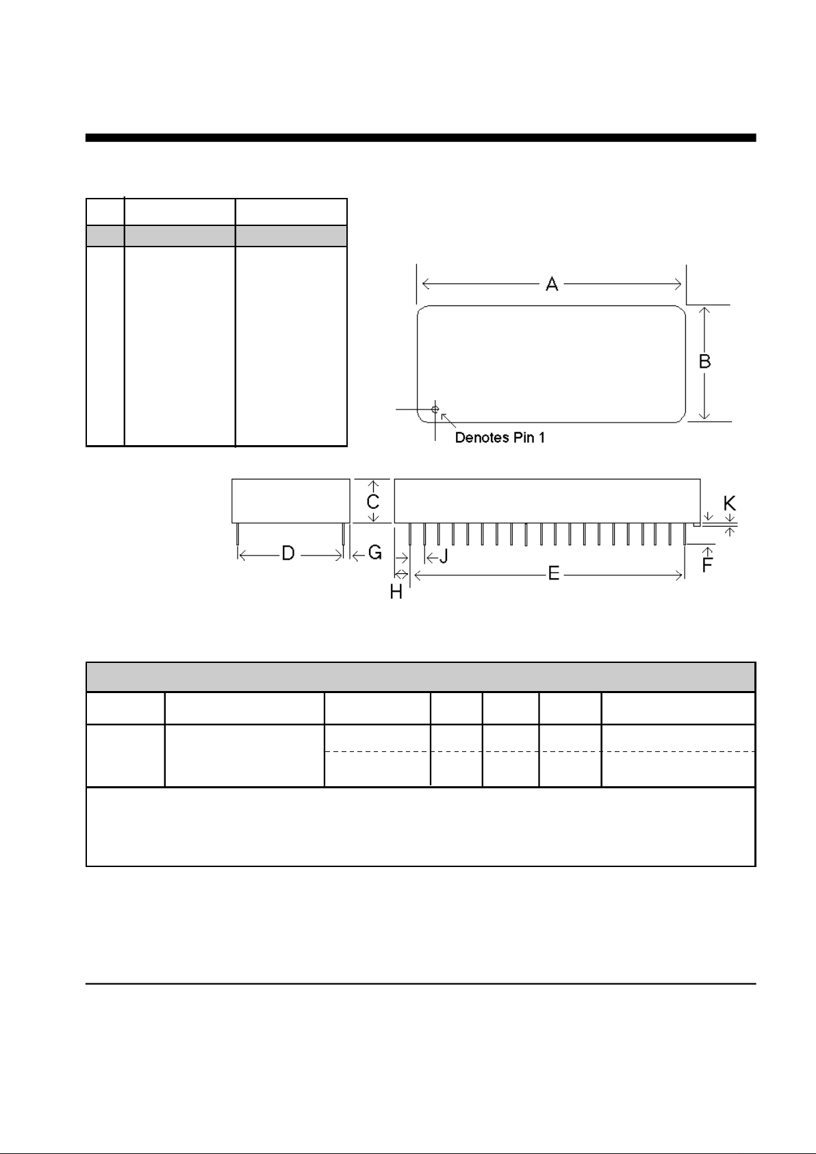
A 2.74 2.760 69.60 70.10
B 1.370 1.390 34.80 35.31
C 0.420 0.430 10.67 10.92
D 1.190 1.210 30.23 30.73
E 1.890 1.910 48.01 48.51
F 0.125 0.200 3.18 5.08
G 0.080 0.100 2.03 2.54
H 0.415 0.435 10.54 11.05
J 0.090 0.110 2.29 2.79
K 0.020 0.025 0.51 0.64
Mechanical Specifications - XE2814
Pins = 0.025 inch square pin
All pins tin-plated
INCHES METRIC(MM)
PIN MIN MAX MIN MAX
Power Management:
The XE2814 has an integrated power management capability. If no activity is
detected on the RXD, DTR, or RI the modem will, within 5 seconds, automatically go into a smart sleep
mode. In this mode power consumption is typically less than 50 milliwatts.
Symbol Parameter Model Typ Max Units Comments
Power Supply Characteristics(TA = 0 - 70°C, Vcc = 5v ±5%)
Vcc Supply Voltage Both 5.0 5.25 Volts
Icc Vcc Supply Current XE2814 180 200 mA Active, On Line
XE2814 10 mA Sleep Mode

PIN NAME I/O DESCRIPTION
3 RXD O Serial data output to the DTE (i.e. external UART). A logic "high represents
a "mark" and a logic "low" represents a "space", TTL.
9 \DTR I Data Terminal Ready, input, active Low, TTL. The function of this pin is set
by the &D command. Normally the modem ignores DTR.
11 \CTS O Clear to Send, output, active Low, TTL/CMOS. This pin regulates the flow
of data from the DTE during hardware flow control.
13 TXD I Serial data input from the DTE (i.e. external UART). A logic "high"
represents a "mark" and a low represents a"space", TTL.
14 \RTS I Request to Send, input, active Low, TTL. This signal regulates the flow of
data from the modem during hardware flow control.
16 \RI O Ring Indicator, output, active Low, TTL. When low indicates the modem is
receiving a ring signal.
19 TIP — Tip connection to the phone line(RJ11 pin3) from the internal DAA.
20 RING — Ring connection to the phone line(RJ11 pin4) from the internal DAA.
Caution: Observe design rules for Tip & Ring trace layout
21 GND — Ground (0 volts)
22 AMP O Audio output function is determined by L & M commands and the value in
register S22. This output can drive a 50Kohm load.
30 OH O DAA hookswitch relay is closed in the "off-hook" position connecting the
DAA to the telephone line.
36 RESET I Hardware reset pin, active High, TTL. Use of an external reset is not
recommended. Any signal applied to Pin 36 must remain high for a
minimum of 100 milliseconds.
38 \DCD O Data Carrier Detect, output, active Low, TTL/CMOS. Function is set by the
&C command and the value in register S21.
39 \DSR O Data Set Ready, output, active Low, TTL/CMOS. Function is set by the &S
command and the value in register S21.
40 Vcc — +5 Volts
XE2814 XECOM\3
Pin Descriptions
4/XECOM XE2814
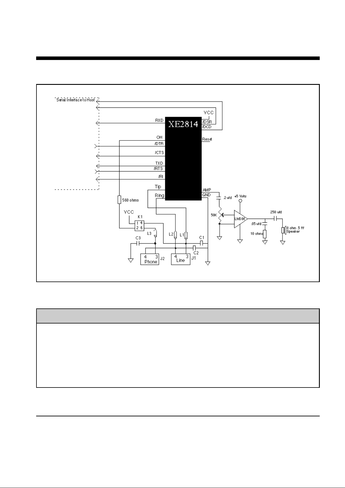
Modem Applications Schematic
Note: RJ11 Pin assignments reflect a 6-pin connector. Tip and Ring are always the center
pin s of the RJ11 jack.
Recommended Parts
Reference Designation Recommended Part Number
L1, L2, L3 TDK CB30-1812
C1, C2, C3 Sprague 30GAT47, 470 pfd, 3000 Volts
J1, J2 Stewart SS6446NF
K1 Theta J LCA110

AT Commands
The XE2814 uses "AT" commands for
control and configuration . Fax is supported
by extensions to the AT commands.
Modes of Operation
The XE2814 has three operational modes;
Command, Fax and Data.
Data Mode: The modem enters data mode
after it establishes a connection and
issues a "CONNECT" result code. In
Data Mode the modem modulates all
signals on Transmit Data and sends
them to the remote modem. The
modem demodulates all signals from the
remote modem and places them onto
Received Data for the host equipment.
When the modem exits data mode, it
issues a "NO CARRIER" result code.
Command Mode: The XE2814 enters
command mode on application of power,
reset, loss of the connection, or receipt
of the escape code. In command mode
the modem accepts commands from the
host on Transmit Data. More than one
command may be placed on each
command line. Appropriate result codes
are returned on Received Data.
Fax Mode: The modem enters Class 1 fax
mode on receipt of AT+FCLASS=1;
AT+FCLASS=2 initiates Fax Class 2.
Fax commands and responses are
issued at 19,200 bits per second; the
character format is 8 bits no parity. Fax
commands are valid only in fax mode.
The A/, ATO, AT&T and escape
commands are not valid in fax mode.
XE2814 XECOM\5
Commands
AT command lines must follow a strict
format. The command line is stored in the
command buffer and executed upon receipt
of a carriage return. Until executed, the
command line can be edited with the
backspace key.
Command Prefix - Each command, except
for the A/ command, begins with the AT
prefix. The "A" and "T" may be either both
caps or both lower case but cannot be of
different cases. The prefix identifies the
speed and parity of the commands sent by
the host. The modem determines speed by
measuring the width of the incoming bits and
parity by comparing the parity bits of the "A"
and the "T." The XE2814 returns result
codes at the speed and parity of the host.
Command Line - Multiple commands may
be placed in a command line. Commands
are executed in the sequence they appear.
Spaces, inserted to improve legibility, do not
fill space in the command buffer. A carriage
return terminates the command line and
causes the commands to be executed.
Register S3 allows the user to select a
character other than a carriage return to
terminate the command line.
Command Buffer - The command buffer
can hold only 40 characters, including the
AT prefix. If the command buffer overflows,
the modem issues an "ERROR" result code
and commands are not executed.

A - Answer Command Bn - Select Communications Standard
n=0 Selects CCITT standards
n=1 Selects Bell standards*
D - Dial Command -
L = Re-dial last number
P = Pulse dial
T = Tone dial
S=n = Dial stored number
W = Wait for dial tone
, = Pause for the duration ofr S8
@ = Wait for silence
! = Switch hook flash
; = Return to the command state
En - Command Echo
n=0 Do not echo commands
n=1 Enable command echo*
Hn - Switch Hook Control -
n=0 Switch hook relay opens*
n=1 The switch hook relay closes
In - Modem Identification
Ln - Speaker Volume -
n=0 Lowest speaker volume
n=1 Low speaker volume
n=2 Moderate speaker volume*
n=3 High speaker volume
6/XECOM XE2814
Command Line Editing - The backspace
can be used to edit the command line.
Hitting the backspace key, or Control and H
simultaneously on some systems, erases
the previous character in the command line.
All of the characters can be erased except
for the "A" and "T." Register S5 allows the
user to select a character other than a
backspace to edit the command line.
Re-Execute Last Command - The A/
command causes the modem to re-execute
the last command line. This is the only
command which does not require the "AT"
prefix.
Ommitted Parameters - Most commands
include a parameter which determines the
command function. When this parameter is
omitted from the command string, it is
assumed to be a 0.
Escape Characters - A three character
escape sequence maybe entered while in
data mode to switch the modem into
command mode while remaining on line.
The escape character, set by Register S2,
must be entered 3 times in succession to
execute the escape. The default escape
sequence is "+++."
Result Codes - The modem issues a result
code after each action. Result codes may
be provided as full words, numeric codes or
may be disabled all together. Each result
code ends with a carriage return when
numeric result codes are chosen. When full
word result codes are chosen, a Line Feed
and Carriage Return precede and follow
each result code.
AT Command List

XE2814 XECOM\7
AT Command List (continued)
Mn - Speaker Activity -
n=0 Speaker off
n=1 Speaker on until carrier received*
n=2 Speaker remains on
n=3 Speaker on after dialing until
carrier is detected.
Nn - Data Rate -
n=0 Handshake only at DTE rate
n=1 Negotiate highest common speed*
On - On Line
n=0 Return On Line with no retrain*
n=1 Initiate retrain returning On Line.
Qn - Responses
n=0 Send responses*
n=1 No Responses
Sr? - Interrogate Register Sr=n - Set Register Value Vn - Result Codes -
n=0 Numeric Result Codes
n=1 English Word Result Codes*
Wn - Connect Message Rate -
n=0 Send "CONNECT" at DTE Rate*
n=1 Report line and DTE speed and
Link protocol
n=2 "CONNECT" Reports Link speed
Xn - Result Code Set -
n=0 Result codes 0 to 4
n=1 Result codes 0 to 5 and 10
n=2 Result codes 0 to 6 and 10
n=3 Result codes 0 to 5, 7 and 10
n=4 Full Result codes*
Yn - Long Space Disconnect -
n=0 Long Space Disconnect Disabled*
n=1 Disconnect on long space
Zn - Reset -
n=0 Reset to user profile 0*
n=1 reset to user profile 1
&Cn - DCD Operation
n=0 DCD is forced active.*
n=1 DCD indicates a valid carrier
&Dn - DTR
n=0 DTR is ignored by the modem. *
n=1 Modem switches to command
mode when DTR revoked.
n=2 Disconnect if DTR revoked.
n=3 Soft reset when DTR revoked
&Fn - Return to Factory Defaults
n=0 Restore configuration 0*
n=1 Restore configuration 1
&Gn - Guard Tone
n=0 Guard Tone Disabled*
n=1 550 Hz Guard Tone
n=2 1800 Hz Guard Tone
&Kn - Flow Control
n=0 Disabled
n=3 RTS/CTS
n=4 XON/XOFF
n=5 Transparent XON/XOFF
n=6 RTS/CTS and XON/XOFF
&Ln - Line Type
n=0 Dial-up line operation
n=1 Dedicated (leased) line operation
&Pn - Dial Pulse Make/Break Ratio
n=0 39/61% @ 10 pps*
n=1 33/67% @ 10 pps
n=2 39/61% @ 20 pps
n=3 33/67% @ 20 pps

8/XECOM XE2814
&Qn - Line Connection
n=0 Direct mode (no data buffering)*
n=5 Use Error Correction
n=6 Normal Mode (Speed buffering)
&Sn - DSR Operation
n=0 DSR always active*
n=1 DSR in accordance with V.25.
&Tn - Test Modes
n=0 Exit test mode
n=1 Local analog loopback
n=3 Initiate local digital loopback
n=4 Respond to remote loop request*
n=5 Deny remote loop request
n=6 Intiate a Remote Digital loopback
n=7 Remote digital loopback w self-test
n=8 Local analog loopback w self-test
&Vn - View Configuration Profiles
n=0 View active profile & user profile 0*
n=1 View active profile & user profile 1
&Wn - Store Active Profile
n=0 Store active profile as profile 0*
n=1 Store active profile as profile 1
&Yn - Recall Stored Profile
n=0 Recall profile 0 on power-up*
n=1 Recall profile 1 on power-up
&Zn=x - Store telephone number "x" in
memory location "n"
%En - Line Quality Monitor/Auto Retrain
n=0 Disabled
n=1 Enabled
n=2 Line quality, fallback, fall forward
%L - Read Recevied Signal Level
%Q - Read Line Signal Quality
AT Command List (continued)
\An - MNP Block Size
n=0 Maximum 64 characters
n=1 Maximum 128 characters
n=2 Maximum 192 characters
n=3 Maximum 256 characters*
\Bn - Transmit Break n x 100 msec
\Gn - Modem to Modem Flow Control
n=0 No modem to modem flow control*
n=1 XON/XOFF flow control
\Jn - DTE Rate Adjust
n=0 Serial port speed independent of
link speed*
n=1 Serial port rate automatically
changed to link speed*
\Kn - Break control
Break received from host with
Reliable link established.
n=0 Enter on-line command mode; do
not transmit break
n=1 Purge buffers, immediately
transmit break
n=2 Same as n=0
n=3 Immediately send break
n=4 same as n=0
n=5 Send break in sequence with data*
Break received from host with Direct
link established.
n=0 Immediately transmit break, then
enter on-line command mode
n=1 Immediately send break
n=2 Enter command mode but do not
transmit break signal
n=3 same as n=1
n=4 same as n=0
n=5 same as n=1*

XE2814 XECOM\9
AT Command List (continued)
Break received from modem with
Normal link established.
n=0 Purge buffers, Immediately send
break to the host
n=1 same as n=0
n=2 Immediately send break to the host
n=3 Same as n=2
n=4 Send break in sequence with data.
n=5 Same as n=2*
Host initiates break with \B
command; Reliable link established.
n=0 Purge buffers and immediately
transmit break
n=1 Same as n=0
n=2 Immediately transmit break
n=3 Same as n=1
n=4 Transmit break in sequence w data
n=5 Same as n=4
\Nn - Error Control Selection
n=0 Normal mode, no error correction
n=1 Direct mode, no buffering, no error
correction
n=2 Reliable mode, error correction
required for connection
n=3 V.42 Auto-reliable mode, accept
either an error controlled or nonerror controlled link*
n=4 V.42 Reliable mode, LAPM
required
n=5 MNP required
\On - Originate Reliable Link
)Mn - Cellular Power Level Adjustment
n=0 Disabled during MNP10 link
negotiations
n=1 Adjust power level during MNP10
link negotiations
*Hn - MNP10 Link Negotiation Speed
n=0 Link negotiations occur at the
highest supported speed
n=1 Link negotiations at 1200 bps
n=2 Link negotiations at 4800 bps
-Kn - MNP Extended Services
n=0 No LAPM to MNP10 conversion
n=1 LAPM to MNP10 conversion*
n=2 LAPM to MNP10 conversion but
no MNP Extended Service during
V.42 LAPM answer mode detect.
-Qn - Fallback to V.22bis/V.22
n=0 Fallback enabled only to 4800 bps
n=1 Fallback to 2400 bps or 1200 bps*
@Mn - Initial Cellular Transmit Level
n=0 -26 dBm*
n=1 -30 dBm
n=2-10 -10 dBm
n=11 -11 dBm
n=12 -12 dBm
:
.
n=30 -30 dBmn
n=31 -31 dBm
:En - Compromise Equalizer
n=0 Disabled
n=1 Enabled*

10/XECOM XE2814
Class 1 Fax Command List
AT+FCLASS? - Service Class Indication
n=0 Configured as a data modem
n=1 Configured for Service Class 1.
n=2 Configured for Service Class 2.
AT+FCLASS=? - Service Class Capability
n=0 Configured as a data modem
n=1 Configured for Service Class 1.
n=2 Configured for Service Class 2.
AT+FCLASS=n - Set Service Class
n=0 Configured as a data modem
n=1 Configured for Service Class 1.
n=2 Configured for Service Class 2.
AT+FAE=n - Data/Fax Auto Answer
n=0 Answer as a fax modem only
n=1 Either a fax or data modem
AT+FF - Enhanced Flow Control
AT+FRH<mod> - Receive HDLC Data
3 V.21 Channel 2, 300 bps
24 V.27ter, 2400 bps
48 V.27ter, 4800 bps
72 V.29, 7200 bps
96 V.29, 9600 bps
97 V.17, 9600 bps
98 V.17 short train, 9600 bps
121 V.17, 12,000 bps
122 V.17 short train, 12,000 bps
145 V.17, 14,400 bps
146 V.17 short train, 14,400 bps
AT+FRM<mod> - Receive Fax
(see AT+FRH for "mod" values)
AT+FRS<time> - Receive Silence
AT+FRTn - Receive Test Data
AT+FTH<mod> - Transmit HDLC Data
(see AT+FRH for "mod" values)
AT+FTM<mod> - Transmit Fax
(see AT+FRH for "mod" values)
AT+FTS<time> - Transmit Silence
AT+FTTn - Transmit Test Data

Class 2 Fax Commands
Code Disconnect Cause
53 Invalid respone to the next page
message
54 No response to the End of Page
message after 3 attempts
55 Invalid response to end of page
message
56 No response to End of Mesage
after 3 attempts
57 Invalid response to End of
Message
58 Unable to continue after page
interrupt
70 Unspecified phae B error
71 Receive Response Error
72 Command received error
73 T.30 time out, expected page not
received
74 T.30 time out after end of
messsage received
90 Unspecified Phase C Error
91 Missing End of line after 5
seconds
93 Receive Buffer overflow
94 Bad check sum of frame
100 Receive Phase D errors
101 Invalid response received
102 Invalid command received
103 Unable to continue after page
interrupt
AT+FBOR=n - T.4 Data Bit Order
n=0 Selects direct order for T.4 Data
n=1 Selects reverse order for T.4 data
AT+FBUF? - Buffer Size
AT+FCR=n - Capability to Receive
n=0 Do not pass message data to host
n=1 Pass message data to host
+FCLASS=n - Set Service Class
n=0 Configured as a data modem
n=1 Configured for Service Class 1
n=2 Configured for Service Class 2
n=3 Reserved for Service Class 3
+FCLASS=? - Available Service Class
+FCLASS? - Current Service Class
+FAA=n - Adaptive Answer
n=0 Answer as selected Service Class
n=1 Answers as a data or fax modem.
AT+FAXERR - Fax Error Value
Code Disconnect Cause
0 Normal fax disconnect
1 Ring detected but handshake
unsuccessful
2 Call terminated by the host
3 No telephone loop current
10 Phase A handshaking error
11 No answer, time out
20 Transmit Phase B error
21 Remote cannot receive or send
22 Command error transmit Phase B
23 Invalid command received
24 Response Errors
25 Local capabilites sent 3 times with
no response
26 local capabilities not recognized
27 Failed to train at lowest speed
28 Invalid response received
40 T.4 transmit data error
43 No data from host
50 Transmit Phase D error
51 Invalid Response received in
transmit Phase D
52 No response to the next page
message after 3 attempts
XE2814 XECOM\11

12/XECOM XE2814
Class 2 Fax Command List (continued)
AT+FDCC = VR, BR, WD, LN, DF, ED, BF,
ST -Set DCE Capabilities Parameters
VR - Vertical Resolution
0 98 Lines Per Inch (Normal)
1 196 Lines Per Inch (Fine)
BR - Bit Rate
0 2400 bits per second
1 4800 bits per second
2 7200 bits per second
3 9600 bits per second
4 12,000 bits per second
5 14,400 bits per second
WD - Page Width
0 1728 pixels in 215 millimeters
1 2048 pixels in 255 millimeters
2 2432 pixels in 303 millimeters
LN - Page Length
0 297 millimeters
1 364 millimeters
2 unlimited
DF - Data Compression Format
0 1-D modified Huffman
1 2-D modified Read
ED - Error Correction
0 Disable Error Correction Mode
(Annex A of T.30)
BF - Binary File Transfer
0 Disable Binary File Transfer
1 Enable Binary File Transfer
ST - Scan Time per Line
Normal Resolution Fine Resolution
0 0 milliseconds 0 milliseconds
1 5 milliseconds 5 milliseconds
2 10 milliseconds 5 milliseconds
3 10 milliseconds 10 milliseconds
4 20 milliseconds 10 milliseconds
5 20 milliseconds 20 milliseconds
6 40 milliseconds 20 milliseconds
7 40 milliseconds 40 milliseconds
AT+FDCS? - Current Session Results
AT+FDIS =VR, BR, WD, LN, DF, ED, BF,
ST - Set Current Sessions
Capabilities Parameters
AT+FDR - Begin/Continue Phase C
Receive Data
AT+FDT - Data Transmission
AT+FET=<ppm> - Transmit Page
Punctuation
AT+FK - Terminate Session
AT+FLID<local ID>= - Local ID String
AT+FPHCTO <value>- Phase C Time Out

S-Register Summary
REG. RANGE/UNITS DESCRIPTION DEFAULT
S0 0-255/rings Number of rings to answer on 000
S1 0-255/rings Count number of incoming rings 000
S2 0-127/ASCII Escape character 043
S3 0-127/ASCII Carriage return character 013
S4 0-127/ASCII Line feed character 010
S5 0-32,127/ASCII Backspace character 008
S6 2-255/sec Dial tone wait time 002
S7 1-60/sec Wait time for remote carrier 060
S8 0-255/sec Comma pause time 002
S9 1-255/0.1 sec Carrier detect response time 006
S10 1-255/0.1 sec Delay from loss of carrier to hang up 014
S11 50-255/msec DTMF dialing speed 095
S12 0-255/0.02 sec TIES Escape Code Time Limit 050
S18 0-255/sec Modem test timer 000
S24 Bit Mapped Sleep Mode timer 010
S25 Bit Mapped DTR Transitions 005
S30 0-255/10msec Disconnect on Inactivity Timer 000
S32 0-255 /ASCII XON Character 017
S33 0-255 / ASCII XOFF Character 019
S37 Bit Mapped Maximum Link Speed 000
S46 136/138 Data Compression Control 138
S48 0,7,128 V.42 Negotiations 007
S86 0,4,5,9,12-14 Call Failure Codes 000
XE2814 XECOM\13

14/XECOM XE2814
Result Codes
DIGIT FULL DEFINITIONS
0 OK Successfully executed command line
1 CONNECT 300 bps connection established
2 RING Ring signal detected
3 NO CARRIER Carrier not detected or Carrier lost
4 ERROR Error found in command line; returns to command mode
5 CONNECT 1200 1200 bps connection established
6 NO DIAL TONE No dial tone detected within 5 Sec. after going off-hook
7 BUSY Busy signal detected after automatically dialing a call
8 NO ANSWER 5 seconds of silence not detected
10 CONNECT 2400 Connection established with 2400 bps link or DTE speed
11 CONNECT 4800 Connection established with 4800 bps link or DTE speed
12 CONNECT 9600 Connection established with 9600 bps link or DTE speed
13 CONNECT 7200 Connection established with 7200 bps link or DTE speed
14 CONNECT 12000 Connection established with 12,000 bps link or DTE speed
15 CONNECT 14400 Connection established with 14,400 bps link or DTE speed
16 CONNECT 19200 Connection established with 19,200 bps DTE speed
17 CONNECT 38400 Connection established with 38,400 bps DTE speed
18 CONNECT 57600 Connection established with 57,600 bps DTE speed
19 CONNECT 115200 Connection established with 115200 bps DTE speed
22 CONNECT 75TX/1200RX V.23 originate connection established
23 CONNECT 1200TX/75RX V.23 answer connection established
33 FAX Fax connection established
35 DATA Data connection established in Fax mode
40 CARRIER 300 300 bps carrier received
44 CARRIER 1200/75 V.23 reverse channel carrier received
45 CARRIER 75/1200 V.23 forward channel carrier received
46 CARRIER 1200 1200 bps carrier received

Result Codes (continued)
47 CARRIER 2400 2400 bps carrier received
48 CARRIER 4800 4800 bps carrier received
49 CARRIER 7200 7200 bps carrier received
50 CARRIER 9600 9600 bps carrier received
51 CARRIER 12000 12,000 bps carrier received
52 CARRIER 14400 14,400 bps carrier received
53 CARRIER 16800 16,800 bps carrier received
54 CARRIER 19200 19,200 bps carrier received
55 CARRIER 21600 21,600 bps carrier received
56 CARRIER 24000 24,000 bps carrier received
57 CARRIER 26400 26,400 bps carrier received
58 CARRIER 28800 28,800 bps carrier received
59 CONNECT 16800 Connection established with 16,800 bps link or DTE speed
61 CONNECT 21600 Connection established with 21,600 bps link or DTE speed
62 CONNECT 24000 Connection established with 24,000 bps link or DTE speed
63 CONNECT 26400 Connection established with 26,400 bps link or DTE speed
64 CONNECT 28800 Connection established with 28,800 bps link or DTE speed
66 COMPRESSION: CLASS 5 MNP Class 5 data compression has been established
67 COMPRESSION: V.42bis V.42bis data compression has been established
69 COMPRESSION: NONE The link was established without data compression
76 PROTOCOL: NONE The link was established without error correction
77 PROTOCOL: LAPM The link was established with LAPM error correction
80 PROTOCOL: ALT The link was established with MNP error correction
81
PROTOCOL: ALT CELLULAR
The link was established with MNP error correction
+F4 +FCERROR Fax carrier error detected
DIGIT FULL DEFINITIONS
XE2814 XECOM/15

16/XECOM XE2814
Telephone Line Impedance Match 600 ohms
Ring Detect Sensitivity 38 Vrms
(on hook, Type B ringer)
Telephone Line Holding Current 0 20 100 mA
Telephone Line Interface Specifications
PARAMETER MIN TYP MAX UNIT
ABSOLUTE MAXIMUM RATINGS*
Electrical Specifications
SUPPLY VOLTAGE - Vcc +6.5 Volts
DC INPUT VOLTAGE -0.6 Volts to +6.5 Volts
STORAGE TEMPERATURE RANGE -25° C TO +85° C
LEAD TEMPERATURE (Soldering, 2 sec per wave) 260° C
OPERATING TEMPERATURE RANGE 0 TO 70° C
*Exceeding these values may result in permanent damage to the device.
I/O Characteristics
Signals Description
DIGITAL INPUTS Input High Input Low
/DTR, /RTS, TXD, RESET min. 2.0 V max. 0.8 V
DIGITAL OUTPUTS Output High Output Low Current Drive
AR, /RI min. 2.4 V max. 0.8 V 15 ma
/CTS, /DSR, /DCD, RXD min. 2.4 V max. 0.4 V 1.6 ma

PARAMETER MIN TYP MAX UNIT COMMENTS
DTMF Level -2.2 0 dBm
DTMF Twist (Balance) 3 dB
DTMF Tone Duration 70 ms
Pulse Dialing Rate 10 pps
Pulse Dialing Make/Break 39/61 % USA
33/67 % CCITT
Pulse Interdigit Interval 785 ms
Billing Delay Interval 2.0 sec.
Tone Detection Bandpass Frequency 290 665 Hz 3 dB point
Tone Detection OFF to ON Threshold -33 dBm into 600 ohms
Tone Detection ON to OFF Threshold -35 dBm into 600 ohms
Dial Tone Detect Duration 3.0 sec.
Ringback Tone Detect Duration 0.75 sec.
Cadence 1.5 sec. OFF/ON Ratio
Busy Tone Detect Duration 0.2 sec.
Cadence 0.67 1.5 sec. OFF/ON Ratio
Other Performance Specifications
XE2814 XECOM\17

FCC Instructions
XE2814 XECOM\18
This product complies with Part 68 of the FCC Rules and Regulations. Each device shipped includes a label which
contains the FCC Registration Number and Ringer Equivalence (REN). If requested, this FCC information must be
provided to the telephone company. A registration label must be affixed to the cabinet's exterior for each device
mounted within a closed assembly.
Ringer Equvalence (REN) is used to calculate the number of devices you may connect to one telephone line and still
have all of the devices respond to an incoming call. Typically, the sum of the RENs of all devices connected to one
line should not exceed five (5.0). Contact your local telephone company to determine the maximum REN for your
area.
Mount this device in the final assembly so as to prevent exposure to any hazardous voltages in the system and to
preserve t he h igh voltage protection b etween Tip /Ring and the rest o f th e system. Install at ion must provi de
adequate separation and restraint of cables and cords. Xecom recommends maintaining a minimum of .100 inches
between t he Tip and Ring traces and all other circuits . No circui try m ay be added between Tip/ Ri ng and the
telephone line connection unless specifically allowed by the rules.
This device requires use of an RSOC RJ-11C jack for the telephone line connection. The jack selected must be
certified to meet FCC Part 68 subpart F requirements.
If you experience trouble with this device, contact XECOM at (408)945-6640 to obtain service. There are no repairs
the c usto mer may make t o this devi ce. If your sys tem cau ses h arm to the tel ep hone netw ork, t he telephone
company may discontinue service temporarily until the problem has been corrected or it is demonstrated that the
device is not m alfunct ioning. If poss ib le, y ou wil l be notified in advance that service is bei ng discontinued. If
advance notice is not practical, you will be notified as soon as possible.
Your telephone company may make changes to their facilities, equipment, or operation that affect proper functioning
of your equipment . You will b e n otified in advanc e of s uc h c hanges t o give you the oppo rtunity to m ai nt ain
uninterrupted telephone service.
This device cannot be used on coin operated telephone lines provided by the telephone company. Connection of
this equipment to party lines is subject to state tariffs.
Any one using this device for fax transfer must include sender identification information as required in the Telephone
Consumer Protection Act of 1991. The Telephone Consumer Protection Act of 1991 makes it unlawful to send a fax
without clearly identifying the fax sender (business or individual) and the number of the transmitting fax machine.
This information may be provided either on the first page of the fax or in the top or bottom margin of each page. The
nu mber listed may n o t b e a 900 number o r other n umber for whic h ch arges exceed l ocal or long di stance
transmission.
The final assembler must provide these FCC instructions to the end user of the equipment.

Devices sold by XECOM are covered by the warranty provisions appearing in its Terms of Sale
only. XECOM makes no warranty, express, statutory, implied, or by description regarding the
information set forth herein, or regarding the freedom of the described devices from patent
infringement. XECOM makes no warranty of merchantability or fitness for any purposes. XECOM
reserves the right to discontinue production and change specifications and prices at any time and
without notice. This product is intended for use in normal commercial applications. Applications
requiring extended temperature range, unusual environmental requirements, or high reliability
applications, such as military, medical life-support or life-sustaining equipment, are specifically not
recommended without additional processing and authorization by XECOM for such application.
Xecom assumes no responsibility for the use of any circuitry other than circuitry embodied in a
Xecom product. No other circuits, patents, or licenses are implied.
Xecom's products are not authorized for use as Critical Components in Life Support Devices or
Systems.
Life Support Devices or Systems are devices or systems which, (a) are intended for surgical
implant into the body, or (b) support or sustain life, and whose failure to perform, when properly
used in accordance with instructions provided in the labeling, can be reasonably expected to result
in significant injury to the user.
A Critical Component is any component of a life support device or system whose failure to
perform can be reasonably expected to cause failure of the life support device or system, or to
affect its safety or effectiveness.
Terms of Sale
Life Support Policy
19/XECOM XE2814
Copyright, Xecom © 1996
While Xecom, Inc. has made every effort to ensure that the information presented here is accurate, Xecom will not be liable for
any damages arising from errors or omission of fact. Xecom reserves the right to modify specifications and/or prices without
notice. Product mentioned herein are used for identification purposes only and may be trademarks and/or registered
trademarks of their respective companies.
X e co m Incorporated
374 Turquoise Str eet ,Mi l pitas, CA 95035
Ph:408-945-6640 Fax:4 08-94 2 - 1 346 E-Mail: info@xecom.com
XECOM
 Loading...