

Page 1
XE2420
2400 BPS Surface-Mountable Integrated Sealed-Hybrid Modem
March 2002
Description
Xecom’s XE2420 provides a complete 2400 BPS
modem into an inexpensive miniature, surface-mount
package. Xecom’s new HyPLCC™ package (Hybrid
PLCC) makes it possible to meet the conflicting goals
of small size, low cost and surface-mountability. The
XE2420 targets remote monitoring applications in
industrial, commercial and residential locations
As a complete modem, the XE2420 includes not only
all modem circuitry but also user transferrable FCC
Part 68 Registration and UL60950 recognition. This
allows the XE2420 to be safely integrated into your
embedded application.
Xecom’s new HyPLCC™ package infuses the XE2420
with both its small size and surface mountability. The
HyPLCC package allows complex hybrid circuits to fit
the 68-Pin PLCC footprint. The HyPLCC™ package
provides a completely sealed enviroment protecting
the XE2420 during assembly and board cleaning
operations.
Features
* Small Size: The HyPLCC™ measures less than 1
inch by 1inch square and 0.290 inches thick
* Surface-mountabile: The HyPLCC™ package is
equivalent to a 68-Pin PLCC device.
* Data transfer at 2400, 1200 and 300 BPS using
V.22bis, V.22, V.23, V.21, Bell 202, Bell 212A, and
Bell 103 Protocols
* Modem Control and Configuration via industry
standard A T Commands.
* Supports external shared line features permitting
unobtrusive sharing of a local telephone line.
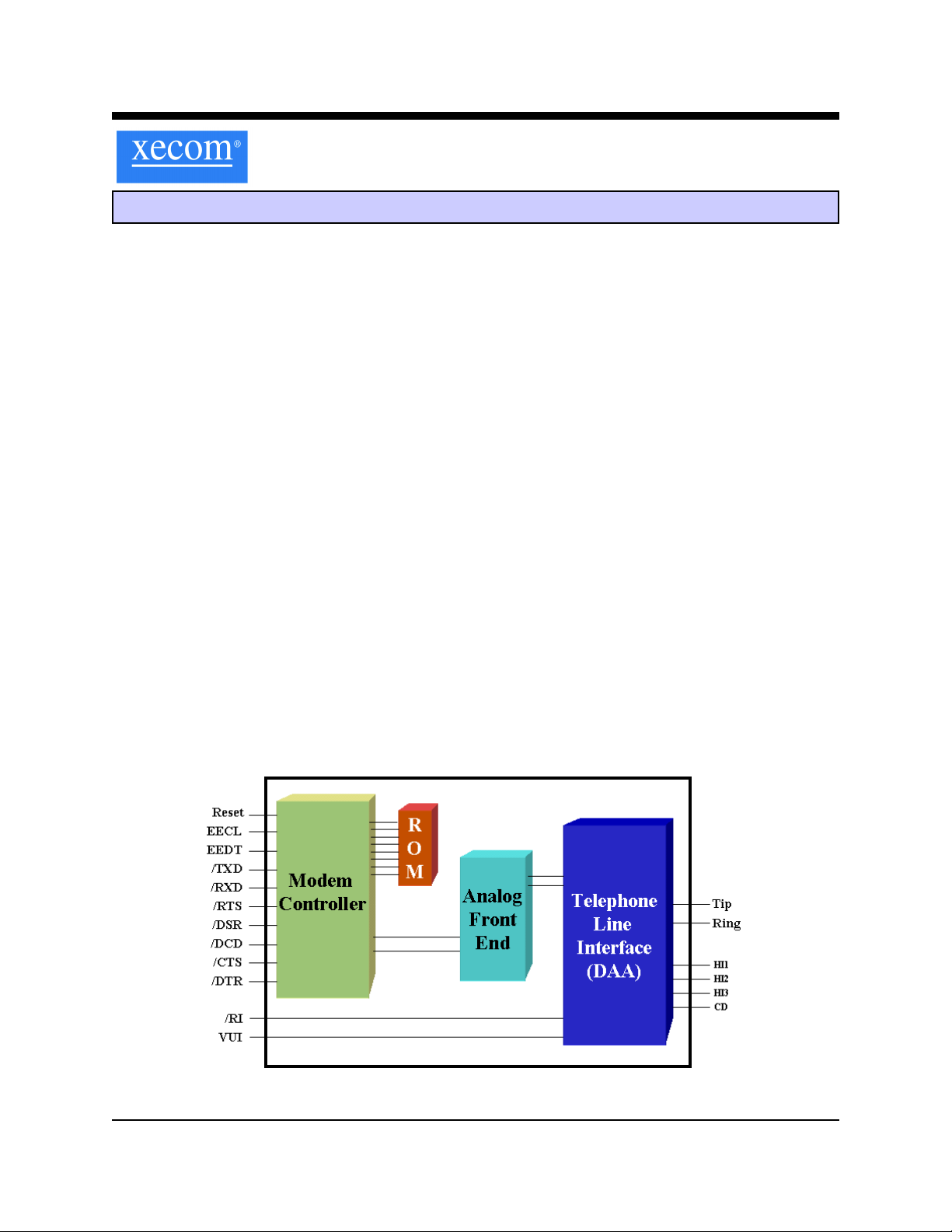
* Complete integrated DAA includes, Ring Detect,
Loop Current Holding Circuit, Hook Switch. Metalic
Surge Protection, and Telephone Line Transformer
* User Transferrable FCC Part 68 Registration
* UL60950 Recognition
* Low Power operation, 330 milliWatt; Power down
operation less than 1 microWatt
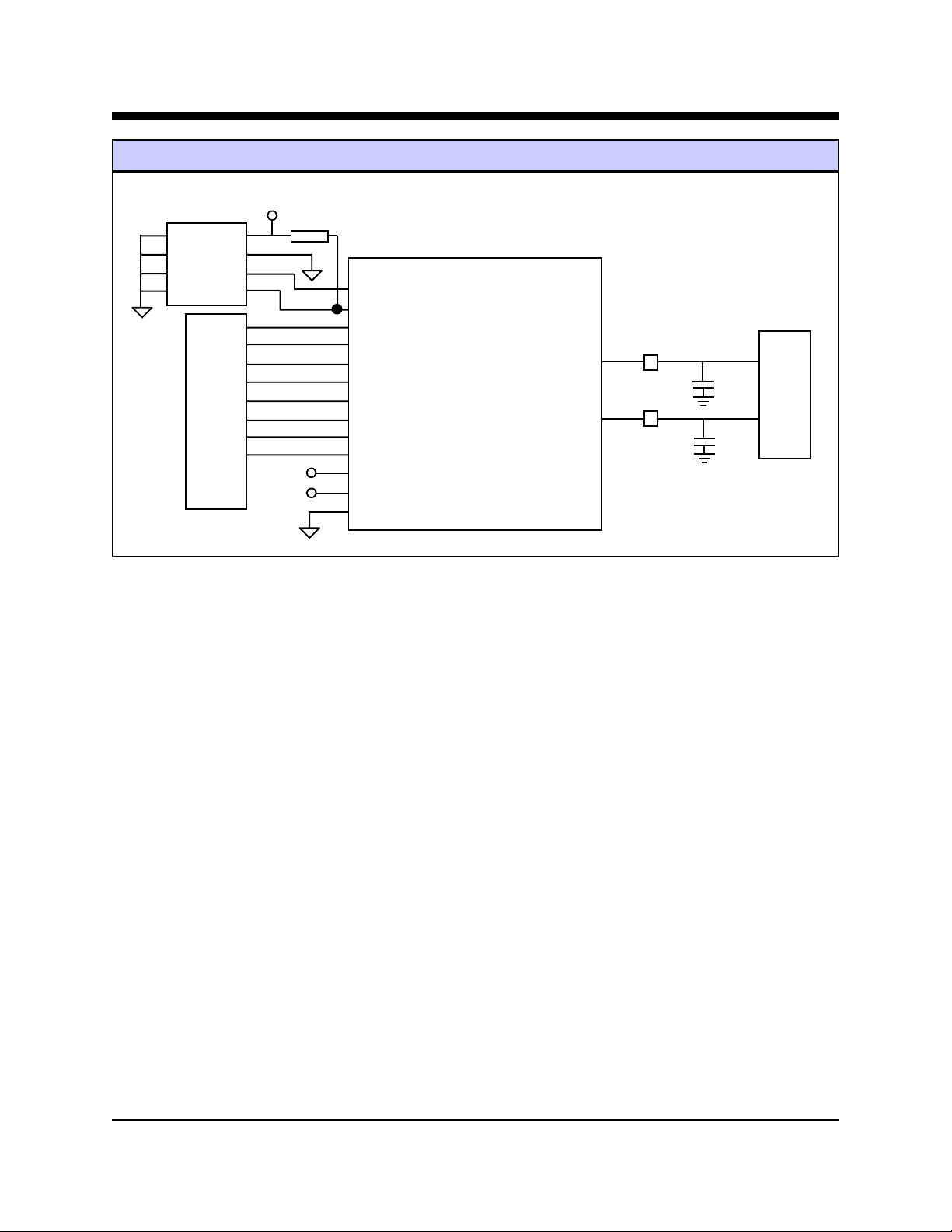
XE2420 BLOCK DIAGRAM
XECOM (1) XE2420
Page 2
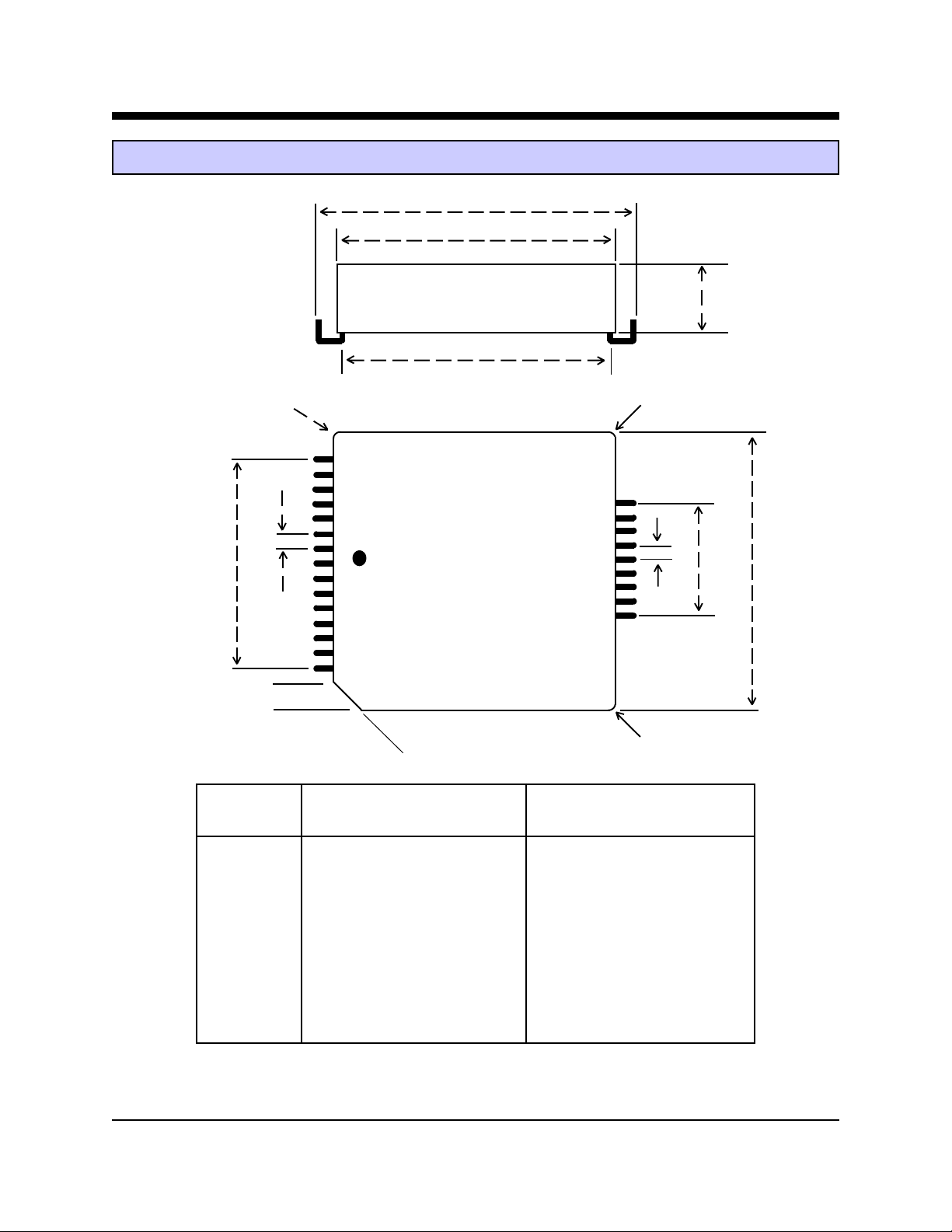
XE2420 Mechanical Specifications
b
c
a
d
i
f
(TOP)
e
i
g
e
.050”
O
45
i
Inches Millimeters
Dimension Min T yp Max Min Typ Max
a 0.280 0.285 0.290 7.11 7.24 7.37
b 0.985 0.990 0.995 25.02 25.15 25.27
c 0.950 0.955 0.960 24.13 24.26 24.38
d 0.910 0.920 0.930 23.11 23.37 23.62
e 0.045 0.050 0.055 1.15 1.27 1.40
f 0.695 0.700 0.705 17.65 17.78 17.91
g 0.395 0.400 0.405 10.03 10.16 10.29
c
i(radius) 0.015 0.020 0.025 0.13 0.25 0.38
XECOM (2) XE2420
Page 3
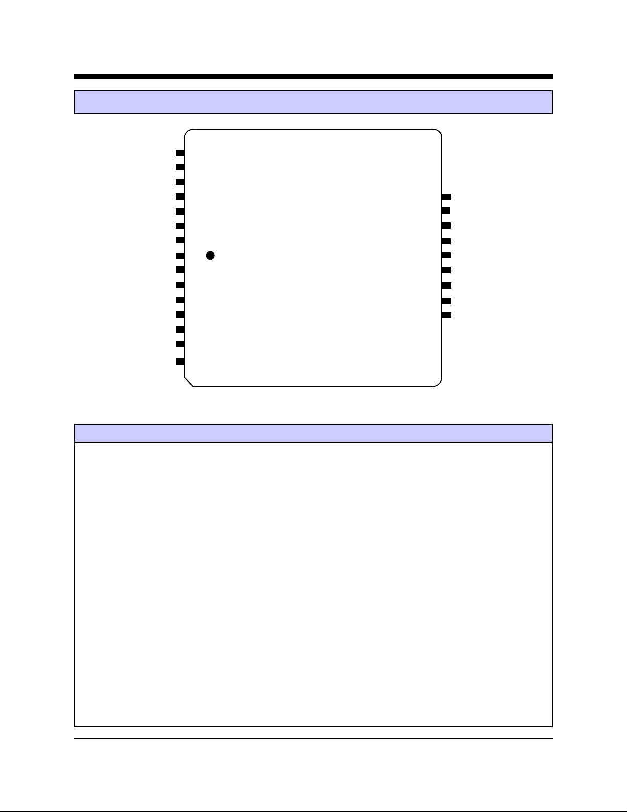
XE2420 Pin Configuration
/DCD 1
/CTS 2
RESET 3
/DSR 4 24 RING
/RTS 5 2 3 N/C
/DTR 6 22 TIP
/RXD 7 2 1 N/C
/TXD 8 2 0 N/ C
/RI 9 19 HI3
GND 10 18 HI1
N/C 11 17 C D
EECL 1 2 16 HI 2
EEDT 1 3
Vcc 1 4
Vui 1 5
TOP
Pin Descriptions
PIN NAME DESCRIPTION
1 /DCD /DCD is an active low output from the modem. The AT&C command controls when the
XE2420 asserts /DCD.
2 /CTS /CTS is an active low output from the modem. The modem asserts /CTS to indicate that it can
accept data from the terminal equipment on /TXD.
3 RESET RESET is an active high input which intiates a modem hardware reset. RESET must be active
for a minimum of 100 milliseconds for a proper modem reset sequence. No external reset is
required; if none is used the RESET signal should be left open.
4 /DSR /DSR is an active low output from the modem. The AT&S command controls when the XE2420
asserts /DSR.
5 /RTS /RTS is an active low input to the modem. /RTS indicates to the modem that the host has data
to send.
6 /DTR /DTR is an active low input to the modem. The AT&D command determines how the modem
will interpret activity on /DTR.
7 /RXD /RXD provides the path for received data and modem responses to be sent from the modem to
the host terminal equipment.
XECOM (3) XE2420
Page 4

XE2420 Pin Descriptions (continued)
PIN NAME DESCRIPTION
8 /TXD /TXD provides the path for transmitted data and modem commands to be passed from the host
terminal equipment to the modem.
9 /RI The /RI signal reports on the presence of an incoming ring signal. When a ring occurs across
Tip and Ring, the /RI output toggles at the ring frequency. The /RI output is powered by Vui
and therefore operates even when VCC is removed from the modem.
1 0 Ground Ground provides the reference voltage for all host interface signals.
11 N/C No internal connection
1 2 EECL EECL provides the clock to the optional external non-volatile memory. The XE2420 requires
a serial 8 by 256 Byte EEPROM for telephone number storage. If the non-volatile memory is
not used, EECL should remain unconnected.
13 EEDT EEDT provides the serial data connection for the optional, external non-volatile memory. The
XE2420 requires a serial 8 by 256 Byte EEPROM for telephone number storage. If the non-
volatile memory is not used, EEDT should remain unconnected.
14 VCC VCC provides 5 volt power to the modem. The RI output is not powered by VCC but by Vui.
1 5 Vui Vui provides uninterrupted power to the XE2420 ring detect circuit. Placing 5 volt power on
Vui insures that the /RI ouput will operate when VCC is removed from the modem.
1 6 HI2 HI2 is one of the four hardware hooks for connecting shared line features to the XE2420.
HI2 interfaces to the 911 Interrupt circuit. This circuit detects changes in the loop current
when an extension handset is lifted as when making an emergency call. The system host
should immediately abort the modem connection to permit the user to complete their call.
See the Application Note on Page 10 of this data sheet to see how these line monitoring
circuits interface with the XE2420.
1 7 CD CD provides another of the four hardware hooks for connecting shared line features to the
XE2420. CD interfaces to the Connect Dectect circuit. Connect Detect allows the system
host to check the status of the telephone line before going off-hook to initiate a call. If the
phone line is in use,the host can delay its call until the telephone line is free. See the
Application Note on Page 10 of this data sheet to see how these line monitoring circuits
interface with the XE2420.
1 8 HI1 HI1 is one of the four hardware hooks for connecting shared line features to the XE2420.
HI1 interfaces to the 911 Interrupt circuit. This circuit detects changes in the loop current
when an extension handset is lifted as when making an emergency call. The system host
should immediately abort the modem connection to permit the user to complete their call.
See the Application Note on Page 9 of this data sheet to see how these line monitoring
circuits interface with the XE2420.
XECOM (4) XE2420
Page 5

XE2420 Pin Descriptions (continued)
PIN NAME DESCRIPTION
1 9 HI3 HI3 is one of the four hardware hooks for connecting shared line features to the XE2420.
HI3 interfaces to the 911 Interrupt circuit. This circuit detects changes in the loop current
when an extension handset is lifted as when making an emergency call. The system host
should immediately abort the modem connection to permit the user to complete their call.
See the Application Note on Page 10 of this data sheet to see how these line monitoring
circuits interface with the XE2420.
20 N/C No internal connection, To prevent damage in case of voltage surges on the telephone line, we
recommend that nothing be connected to this pin.
21 N/C No internal connection, To prevent damage in case of voltage surges on the telephone line, we
recommend that nothing be connected to this pin.
2 2 Tip The Ring and Tip signals provide modem the connection to the telephone line. FCC Part 68
Rules require a 1500 volt isolation barrier between the telephone line and all other circuits.
This isolation must be preserved throughout the system.
The telephone company places a DC “Battery” voltage across Tip and Ring on all public switched
telephone lines. The XE2420 will operate regardless of the polarity of this “Battery” voltage.
The “Battery” voltage drives up to 100 milliamps of DC loop current.
UL60950 requires minimum creepage and clearances distances be maintained between the
Tip and Ring traces and all other circuits. Clearance is the shortest distance between conductive
circuits; creepage is the distance between conductive surfaces along the surface
23 N/C No internal connection, To prevent damage in case of voltage surges on the telephone line, we
recommend that nothing be connected to this pin.
2 4 Ring The Ring and Tip signals provide modem the connection to the telephone line. FCC Part 68
Rules require a 1500 volt isolation barrier between the telephone line and all other circuits.
This isolation must be preserved throughout the system.
The telephone company places a DC “Battery” voltage across Tip and Ring on all public switched
telephone lines. The XE2420 will operate regardless of the polarity of this “Battery” voltage.
The “Battery” voltage drives up to 100 milliamps of DC loop current.
UL60950 requires minimum creepage and clearances distances be maintained between the
Tip and Ring traces and all other circuits. Clearance is the shortest distance between conductive
circuits; creepage is the distance between conductive surfaces along the surface.
XECOM (5) XE2420
Page 6
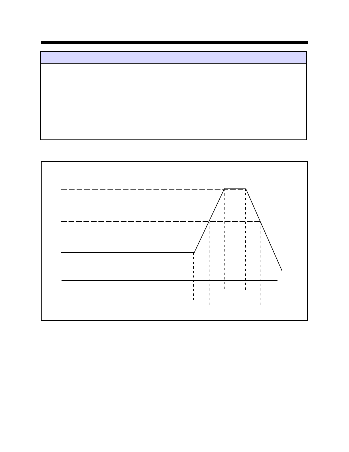
XE2420 Soldering Instructions
The XE2420 is subject to damage if over-exposed to heat during solder reflow operations. Following the
soldering instructions below will ensure that the process of soldering the module to the board does not damage the
modem. The XE2420 must not be exposed to direct Infrared (IR) heating. If your process includes direct IR
heating, you must shield the XE2420 from the infrared rays.
Maximum Temperature 220O C
Maximum Time at 220O C 20 Seconds
Maximum Time above Eutectic (180O C) 90 Seconds
Maximum Preheat Dwell Time 180 Seconds
Maximum Recommended Solder T emperature Profile
220O C
180O C
150O C
--------------------------------180 sec max --------------------- max
-20 sec-
----- 90 sec max -----
XECOM (6) XE2420
Page 7
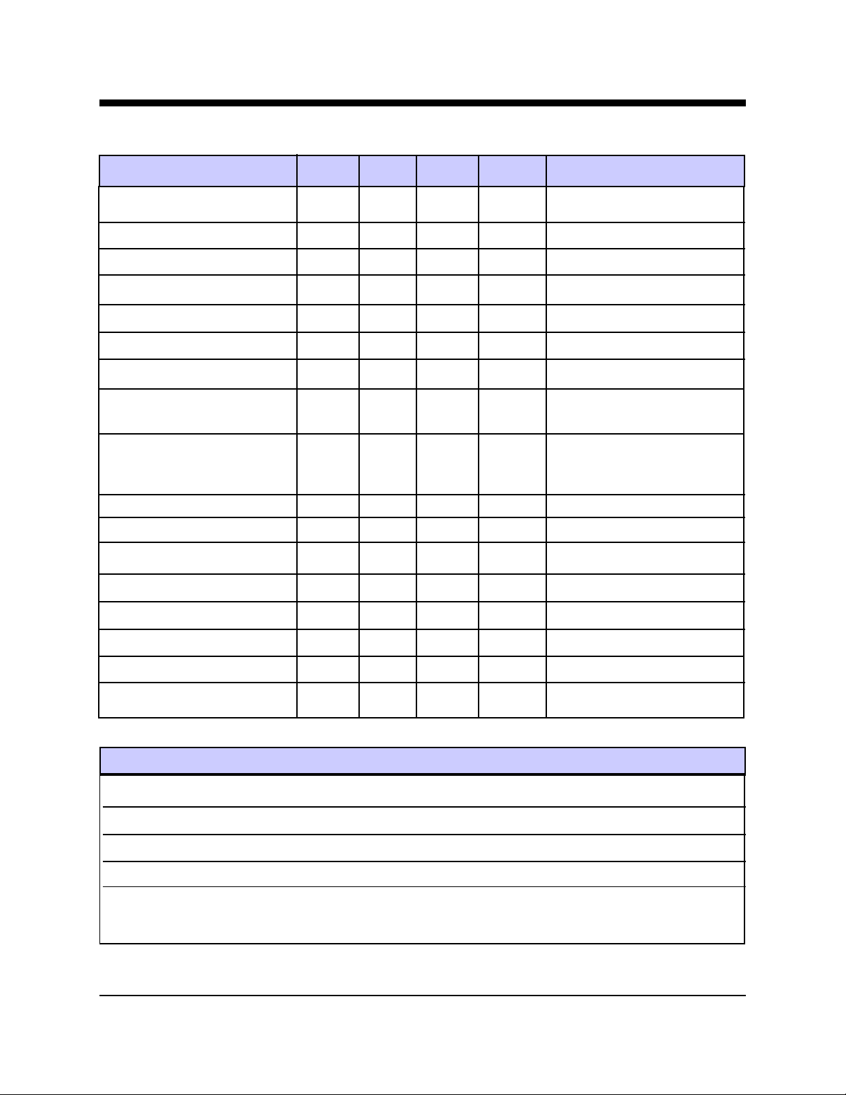
XE2420 Electrical Specifications
Parameter M in Typ Max Units Comments
VCC 4.75 5.25 Volts
ICC 60 66 72 ma On Line
ICC 25 ma idle
Vui 4.75 5.25 Volts
Iui 1 µa No Ring Signal Present
Ring Voltage Detected 38 150 RMS Type B Ringer
Ring Frequency Detected 15.3 68 Hz Type B Ringer
Connect Detect Sensitivity 2 0 Volts DC Battery Voltage level detected by
circuit shown on Page 10
Handset Interrupt Detection 1. 0 Volts DC Change in Battery Voltage
detected by circuit shown on
Page 10
Telephone Loop Current 1 0 4 0 10 0 ma
Line Impedance 600 Ohms
Data Transmit level -12 -10 -9 dBm
DTMF Transmit Level -2.5 0 dBm Av g over 3 second interval
Voh 2.4 Volts
Vol 0.4 Volts
Vih 2.0 VCC+0.3 Volts
Vil -0.3 0.8 Volts
XE2420 ABSOLUTE MAXIMUM RA TINGS
Storage T emperature -25O C to +85O C
Operating T emperature Range
Maximum Time Above Eutectic (183O C) 90 seconds
Preheat Dwell Time 120 to 180 seconds
1
The XE2420 can be ordered with an Operating Temperature of -40O C to +85O C at extra cost. Order XE2420-ITR or
to specify Industrial Temperature Range (ITR).
1
0O C to +70O C
XECOM (7) XE2420
Page 8
XE2420 T ypical Application Schematic
/TXD
/RXD
/RTS
/RI
/DSR
/DCD
/CTS
/DTR
+5 V olts
+5 V olts
Battery
20K
XE2420
Reset
EECL
EEDT
/TXD
/RXD
/RTS RING
/RI
/DSR
/DCD TIP
/CTS
/DTR
Vcc
Vui
Gnd
RJ11
FB1
C1
FB2
C2
NM24C04
A0 VCC
A1 WP
A2 SCL
VSS SDA
16C550
UART
Notes:
1 FB1 and FB2 are ferrite beads which may be required for EMI filtering in your system. Without these
components you may experience unintended radiation when the telephone cable is attached to your system.
We recommend selecting components such as the TDK ACB2012L-120 which provide a minimum of 100
ohms of impedence at frequencies above 100 MHz.
2. C1 and C2 are high-voltage capacitors which may be required for EMI filtering in your system. Without these
components you may experience unintended radiation when the telephone cable is attached to your system. W e
recommend selecting components such as the Panasonic ECKDRS471. This 470 pfd, 3000 volt capacitor will
direct the high frequency harmonics to the system ground. These capacitors must be rated at a minimum of 1500
volts to maintain the isolation required by FCC Part 68 Rules.
3. The Battery applied to Vui allows the XE2420’s Ring Indicate output to remain active even when the modem
itself is powered down. If this power-down mode is not required for your application, Vui should be tied to
VCC.
4. The EEPROM, NM24C04, provides for non-volatile storage of telephone numbers using the AT&Z command.
The EEPROM must be programmed using the Diplomat™ Utility from Zilog Inc.
Diplomat™ is a trademark of Zilog Inc.
XECOM (8) XE2420
Page 9
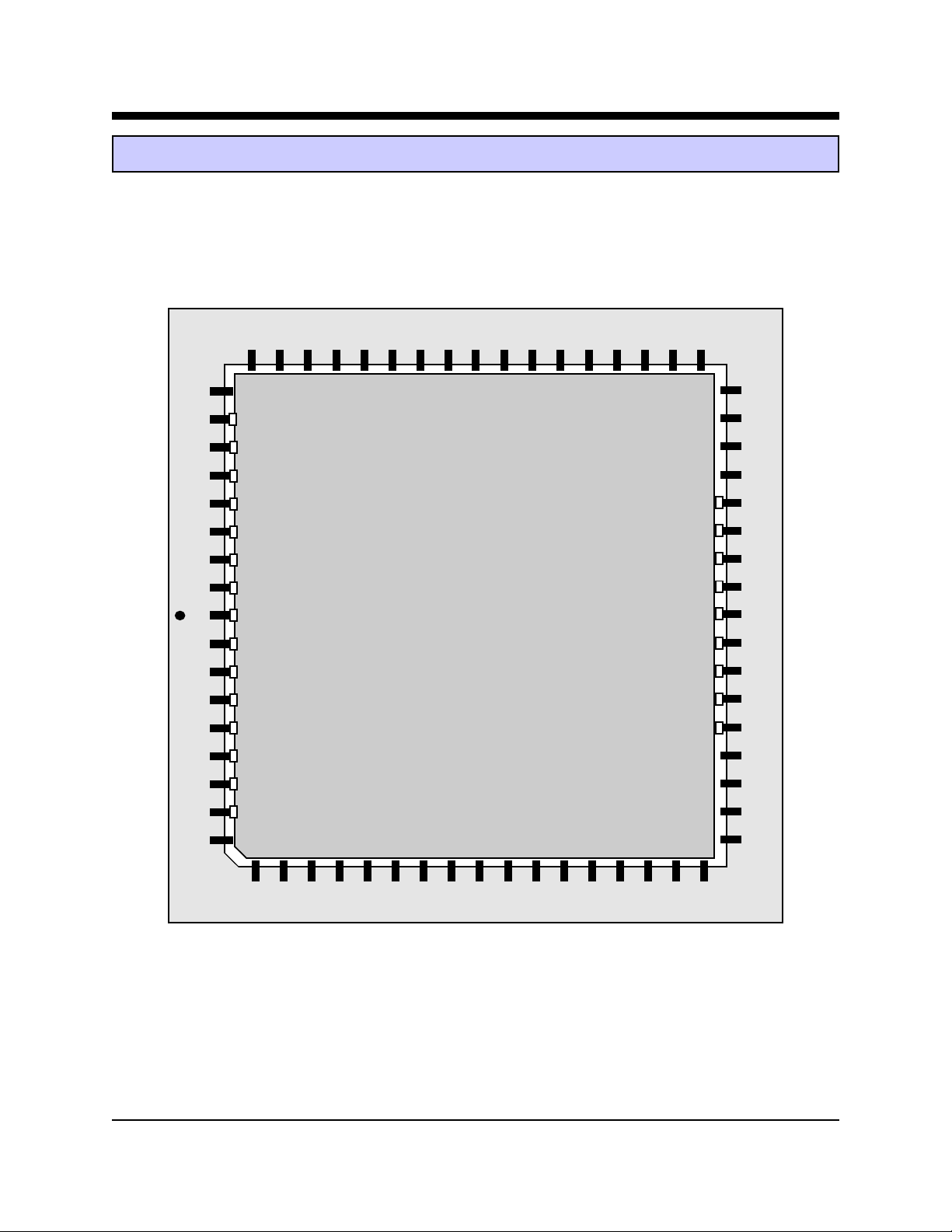
Application Note: Using a 68-Pin PLCC Socket
The XE2420 can be inserted into a socket for a 68-pin PLCC device. The HyPLCC package uses only 24 pins; 15
on one side and 9 on the opposite side. Allignment within the socket is critical for all pins of the XE2420 to
make contact with the appropriate pins of the PLCC socket. The drawing below illustrates how the XE2420 can be
inserted into the 68-pin PLCC socket.
60 44
61 43
1
2
3
424
523
622
721
1
927
820
919
10 18
11 17
12 16
13
14
15
XE2420
10 26
XECOM (9) XE2420
Page 10
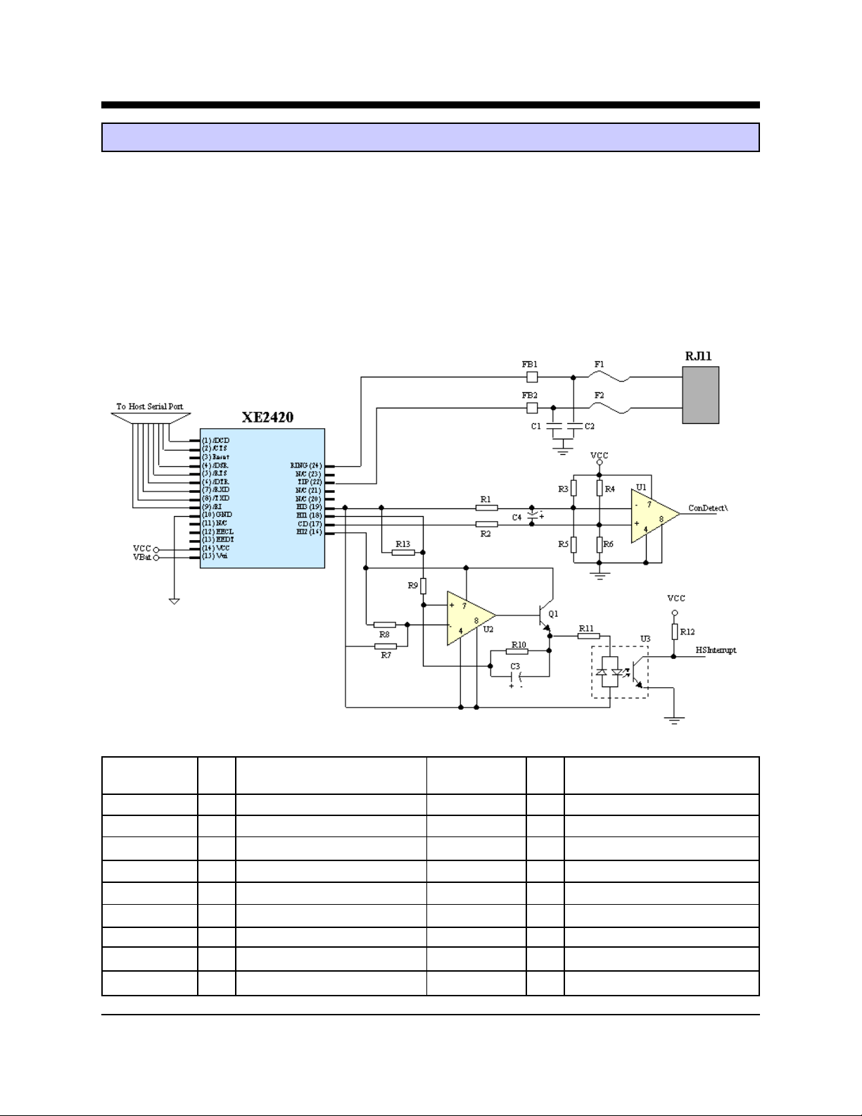
Application Note: XE2420 Shared Line Feature
For applications where the XE2420 shares a telephone line with a telephone handset, Xecom has provided four
hardware hooks for connecting two monitoring circuits. These circuits monitor the status of the telephone line to
prevent the modem from interfering with a voice call.
The Connect Detection Circuit monitors the telephone loop voltage when the modem is not in use. This allows the
system host to check the status of the telephone line before initiating a call. The ConDetect signal will be be high
when the phone line is available but goes low to indicate that the telephone line is in use.
The Handset Interupt or 911 Interrupt circuit monitors loop current while the modem is in the off-hook state. This
circuit detects the change in loop current which occurs when a handset on the shared telephone line is lifted. The
HSInterrupt output will go low momentarily if the handset is lifted during data communications. The system host can
then immediately abort the modem connection and permit the user to complete their call.
Parts List for Shared Line Feature Application Note
Reference Reference
Designation Qty Description Designation Qty Description
C1, C2 2 Cap. 470 pfd 2600V R7 1 Resistor, 56K 5%
C3 1 Cap. 10 ufd 20% 16V R8 1 Resistor, 33K 5%
C4 1 Cap. 1 Ufd, 20% 10V R9 1 Resistor, 402K 5%
F1, F2 2 PTC, TR600-150 R1 0 1 Resistor, 1M 5%
FB1, FB2 2 Ferrite, ACB2012L-120 R11 1 Resistor, 1.5K 5%
Q1 1 Trans. FMMT3904 R1 2 1 Resistor, 20K 5%
R1, R2 2 Resistor, 10M 5% R13 1 Resistor, 100K 5%
R3, R5, R6 3 Resistor, 200K 1% U1, U2 2 OP Amp, TLC271CD
R4 1 Resistor, 280K 1% U 3 1 Opto-coupler, PS2705-1
XECOM (10) XE2420
Page 11

XE2420 AT Commands
The XE2420 uses "AT" commands for configuration and
control. This section describes use of the AT command
format and lists the AT commands, Registers and Result
codes. XE2420 "AT" commands have two operational
modes; Command Mode and Data Mode.
Data Mode: The XE2420 enters data mode after it
connects with a remote modem and issues the appropriate result code. In the Data Mode the modem sends all
data presented on Transmit Data (/TXD) to the remote
modem and puts data from the remote modem onto
Received Data (/RXD). When the modem exits data
mode, it issues a "NO CARRIER" result code.
Command Mode: The XE2420 enters command mode
on power-up, reset, a lost connection, or receipt of the
escape code. In command mode the modem accepts
commands from the host on transmit data. Appropriate
result codes are returned on received data.
Command Line Format
Command lines issued to the modem follow a strict
format. Each command begins with the prefix AT. The
command line is stored in the command buffer and
executed upon receipt of a carriage return. Until
executed, the command line can be edited with the
backspace key.
Command Prefix - Each command, except the A/
command, begins with the AT prefix. The "A" and "T"
may be either both upper case or both lower case but
cannot be of different cases. The prefix identifies the
speed and parity of the commands sent to the modem by
the host. Speed is determined by measuring the width of
the incoming bits. Parity is determined by comparing the
parity bit of the "A" and the "T."
Command Line - Commands may be strung together in
a single command line of up to 36 characters. Commands are executed in the sequence they appear. Spaces
may be inserted into the command line but do not fill
space in the command buffer. A carriage return terminates the command line and causes the commands to be
executed. Register S3 allows the user to select a
character other than a carriage return to terminate the
command line.
Command Buffer - No more than 36 characters,
including the AT prefix, may be loaded into the command buffer. If the command buffer overflows, the
modem issues an "ERROR" result code and commands
are not executed.
Command Line Editing - The backspace edits a
command line before it is executed. The backspace key ,
(Control and H simultaneously on some systems), erases
the previous character in the command line. Register S5
allows the user to select a character other than a backspace to edit the command line.
Re-Execute Last Command - The A/ command causes
the modem to re-execute the last command line. This is
the only command which does not require the "AT"
prefix.
Omitted Parameters - Most commands include a parameter which determines how the functions will be set.
When the command parameter is omitted from the
command string, it is assumed to be a 0.
Escape Characters - A 3 character escape sequence
maybe entered while in data mode to switch the modem
into command mode while on line. The escape character, set by Register S2, must be entered 3 times in
succession to execute the escape. An AT command must
then be enterred within the period defined by S12 to
enter the command mode. The default escape sequence
is "+++."
Result Codes - The modem issues a result code after
each action. Result codes may be provided as full words,
one or two digit numeric codes, or may be disabled all
together. Each result code ends with a carriage return
when numeric result codes are chosen. When full word
result codes are chosen, a Line Feed and Carriage Return
preceed and follow each result code.
XECOM (11) XE2420
Page 12

XE2420 AT Commands
An asterisk indicates the factory default
A - Answer Command -
Bn - Select Communications Standard
n=0 Selects CCITT standards
n= 1 Selects Bell standards*
n= 2 Selects V.23/Bell 202 (see S37)
D - Dial Command -
0-9, A-D, #, * = Dialing Digits
P = Pulse dial
T = Tone dial
R = Connect as an answering modem
W = Wait for dial tone
, = Pause for the duration of S8
@ = Wait for silence
! = Switch hook flash
; = Return to the command state
S=n = Dial Stored Number n
En - Command Echo
n=0 Do not echo commands
n=1 Enable command echo*
Hn - Switch Hook Control -
n=0 Switch hook relay opens
n=1 Switch hook relay closes
In - Modem Identification
Mn - Speaker Activity -
n=0 Speaker off
n=1 Speaker on until carrier received*
n=2 Speaker remains on
n=3 Speaker on after dialing until carrier is detected.
On - On Line
n=0 Return On Line with no retrain*
n=1 Initiate retrain while returning On line.
Qn - Responses
n=0 Send responses *
n=1 No Responses
Sr? - Interrogate Register Sr=n - Set Register Value -
Xn - Result Code Set -
n= 0 Responses 0-4
n=1 Responses 0-5 & 10
n=2 Responses 0-6 & 10
n=3 Responses 0-5, 7 & 10
n=4 Responses 0-7 & 10*
&Cn - DCD Operation
n=0 DCD is forced active*
n=1 DCD indicates a valid carrier signal
&Dn - DTR
n=0 DTR is ignored*
n=1 When the modem is on-line DTR off switches it to
the command mode and issues OK response.
n=2 Modem disconnects if the host revokes DTR.
n=3 The modem performs a soft reset when DTR is
revoked.
&F - Reset Factory Defaults
&Gn - Guard Timer -
n= 0 None *
n=1 550 Hz Guard Timer
n=2 1800 Hz Guard Timer
&Sn - Data Set Ready
n=0 Data Set Ready Forced Active *
n=1 Data Set Ready on at Start of Modem handshake
&Z=x - Store dialing string x
%En - Automatic Retrain
n=0 Automatic Retrain Disabled
n=1 Automatically retrain on poor signal quality *
\Nn - Data Buffering
n=0 Data Bufferred
n= 1 Direct Mode no data buffering *
\Qn - Flow Control
n=0 Flow Control Disabled
n=1 XON/XOFF Flow Control
n=2 CTS Flow Control
n=3 RTS/CTS Flow Control *
n= 4 DCE to DTE XON/XOFF Flow Control
Vn - Result Codes -
n= 0 Numeric Result Codes
n=1 English Word Result Codes*
XECOM (12) XE2420
Page 13

XE2420 Modem Registers
S0 Answer on nth Ring: S0 sets the modem to
automatically answer on the nth ring. Setting S0 to 0
disables automatic answer.
Range: 0 to 255
Units Rings
Default 0
S1 Ring Count: S1 is a read-only register showing the
number of rings detected. If a ring is not detected
within 8 seconds, S1 is reset to zero.
Range: 0 to 255
Units Rings
Default 0
S2 Escape Character: S2 determines the ASCII escape
character. Values of 0-127 select valid ASCII escape
characters; values from 128 to 255 disable the escape
sequence.
Range: 0 to 255
Units ASCII Character
Default 43 (+)
S3 Line T ermination Character: S3 determines the
ASCII character which will terminate commands and
modem responses.
Range: 0 to 127
Units ASCII Character
Default 13 (Carriage Return)
S4 Line Feed Character: S4 sets the ASCII character
to act as a line feed character in modem responses.
Range: 0 to 127
Units ASCII Character
Default 10 (Line Feed)
S5 Backspace Character: S5 defines the ASCII
character used as a backspace to edit the command
line.
Range: 0 to 127
Units ASCII Character
Default 8 (Back Space)
S6 Dial T one Wait Time: S6 determines how long the
modem waits for dial tone before dialing begins. The
Dial Tone Wait Time cannot be set to less than two
seconds.
Range: 2 to 255
Units Seconds
Default 2
S7 Wait for Carrier after Dialing: S7 determines how long
the modem waits for a valid carrier signal after dialing is
completed.
Range: 1 to 255
Units Seconds
Default 30
S8 Comma Pause Time: S8 defines the duration of the
pause initiated by a comma in the dialing string. The pause
is generally used when waiting for a second dial tone.
Range: 1 to 255
Units Seconds
Default 2
S9 Carrier Detect Response Time: S9 establishes the
length of time the remote modem's carrier must be present
to be recognized as valid.
Range: 1 to 255
Units 0.1 Seconds
Default 6
S10 Carrier Off Disconnect Delay: S10 selects how long
carrier must be lost before the modem disconnects. Note:
If S10 is smaller than the value of S9 or S10 is set to 255,
the modem will not automatically disconnect on loss of
carrier.
Range: 1 to 255
Units 0.1 Seconds
Default 1 4
S11 Tone Dialing Speed: S11 sets the duration and spacing
of the dialing tones. S11 does not affect the pulse dialing
rate.
Range: 50 to 255
Units 1 Millisecond
Default 9 5
S12 Escape Code Guard Timer: S12 sets the escape
sequence guard timer. If characters are received before or
after the escape sequence, within the guard timer, the
modem aborts the escape attempt and remains in data
mode.
Range: 0 to 255
Units 0.02 Seconds
Default 5 0
XECOM (13) XE2420
Page 14
XE2420 Modem Registers continued
S28 Inactivity Timer: S28 determines how long the mo-
dem wil remain on line with not data flowing. A 0 in
this register disables the inactivity time out.
Range: 0-255
Units Minutes
Default 0
S29 Hook Flash Time: S29 determines the the amount
of time the modem will go on-hook when a hook
switch flash is called for.
Range: 0-255
Units 0.02 Seconds
Default 25
XE2420 Modem Responses
Digits Verbose Description
0 OK Successfully executed command line
S37 Maximum Line Data Rate: S37 sets the maximum
line data rate or modulation technique that the XE2420
will support for any connection.
Register
Value Communications Supported
0 Maximum Data Rate determined by the
autobaud function of the A T Command
1 Connect using V.23, asymmetrical modem
modulation, 1200/75 BPS
2 Connect using Bell 202, asymmetrical
modulation, 1200/150 BPS
3 V.21, Bel 103, 300 BPS
4 Reserved
5 V.22, Bell212A 1200 BPS
6 V.22bis 2400 BPS
1 CONNECT 300 bps connection
2 RING Ring signal detected
3 NO CARRIER Carrier not detected/lost
4 ERROR Error in command line
5 CONNECT 1200 1200 bps connection
6 NO DIAL TONE No dial tone detected
7 BUSY Busy signal detected
8 NO ANSWER 5 second silence not detected
10 CONNECT 2400 2400 bps Connection
16 CONNECT 1200TX/75RX V.23 Connection transmitting at 1200 BPS
17 CONNECT 75TX/1200RX V.23 Connection transmitting at 75 BPS
18 CONNECT 1200TX/150RX Bell 202 Connection transmitting at 1200 BPS
19 CONNECT 150TX/1200RX Bell 202 Connection transmitting at 150 BPS
XECOM (14) XE2420
Page 15

FCC Instructions
The XE2420 complies with part 68 of the FCC Rules and Regulations. With each device shipped, there is a label which contains, among other information, the FCC Registration Number and Ringer Equivalence Number (REN) for this product. You
must, upon request, provide this information to your telephone company.
The mounting of this device in the final assembly must be made in such a manner as to preserve the high voltage protection between the TIP/RING Connection and the rest of the system. Typically, this may be accomplished by maintaining a minimum
spacing 100 mils between the TIP/RING Traces to the RJ-11C Jack and low voltage portion of the system. No additional circuitry may be attached between TIP/RING and the telephone line connection, unless specifically allowed in the rules.
The REN is useful to determine the quantity of devices you may connect to a telephone line and still have all of these devices
ring when the number is called. In most, but not all areas, the sum of the RENs of all devices connected to one line should not
exceed five (5.0). To be certain of the number of devices you may connect to the line, as determined by the REN, you should
contact the local telephone company to determine the maximum REN for you calling area.
If your system causes harm to the telephone network, the telephone company may discontinue service temporarily. If possible,
they will notify you in advance. If advance notification is not practical, you will be notified as soon as possible.
Your telephone company may make changes in its facilities, equipment, operations or procedures that could affect proper functioning of your equipment. If they do, you will be notified in advance to give you an opportunity to maintain uninterrupted telephone service.
If you experience trouble with this device, please contact XECOM at (408) 945-6640 for information on obtaining service or
repairs. The telephone company may ask you to disconnect this device from the network until the problem has been corrected
or until you are sure that the device is not malfunctioning.
The device may not be used on coin service lines provided by the telephone company (this does not apply to private coin telephone applications which use standard telephone lines). Connection to party lines is subject to state tariffs.
XECOM (15) XE2420
Page 16

Terms of Sale
Devices sold by XECOM are covered by the warranty provisions appearing in its Terms of Sale only. XECOM makes no warranty, express, statutory, implied, or by description regarding the information set forth herein, or regarding the freedom of the
described devices from patent infringement. XECOM makes no warranty of merchantability or fitness for any purposes.
XECOM reserves the right to discontinue production and change specifications and prices at any time and without notice. This
product is intended for use in normal commercial applications. Applications requiring extended temperature range, unusual environmental requirements, or high reliability applications, such as military, medical life-support or life-sustaining equipment, are
specifically not recommended without additional processing and authorization by XECOM for such application.
Xecom assumes no responsibility for the use of any circuitry other than circuitry embodied in a Xecom product. No other circuits, patents, or licenses are implied.
Life Support Policy
Xecom's products are not authorized for use as Critical Components in Life Support Devices or Systems.
Life Support Devices or Systems are devices or systems which, (a) are intended for surgical implant into the body, or (b) support or sustain life, and whose failure to perform, when properly used in accordance with instructions provided in the labeling,
can be reasonably expected to result in significant injury to the user.
A Critical Component is any component of a life support device or system whose failure to perform can be reasonably expected to cause failure of the life support device or system, or to affect its safety or effectiveness.
Copyright, Xecom © 2001
While Xecom, Inc. has made every effort to ensure that the information presented here is accurate, Xecom will not be liable for any damages arising from errors or
omission of fact. Xecom reserves the right to modify specifications and/or prices without notice. Product mentioned herein are used for identification purposes only
and may be trademarks and/or registered trademarks of their respective companies.
Xecom Incorporated
374 Turquoise Street, Milpitas, CA 95035
Ph:408-945-6640 Fax:408-942-1346 E-Mail: [email protected]
XECOM (16) XE2420
 Loading...