

Page 1
XECOM (1) XE924
XE924
October 2002
XE924 Base Access Point for Multiple Remote Machines
Description
Xecom combined proven embedded modem technology
and a 900 MHz transceiver to create the XE924, Base
Access Point. The Base Access Point is a simple scheme
to connect multiple remote systems to a single dial-up
telephone line. Each of the remote systems
communicates with the Base Access Point using
Xecom’s XE900 Smart Transceiver. The XE924
eliminates hardware redundancy, and therefore reduces
both the initial investment and operating costs.
Xecom’s Base Access Networking scheme significantly
reduces hardware costs in locations with multiple
systems. For example, credit card verification normally
requires a dedicated modem and telephone line for each
sales terminal. Each time a terminal is added another
modem and another telephone line also need to be added.
The Base Access Point connects all of the terminals
through one shared modem and telephone line. The
only hardware requirement is the addition of an XE900
Smart Transceiver to the terminal equipment.
This scheme also eliminates the installation requirements
of a wired network. Whether you add a system equipped
with a Smart Transceiver to the network or build a new
facility, the 900 MHz wireless link eliminates the need to
install cables and configure a server. By virtue of its
commonality with millions of cordless telephones the
XE924 also offers the most cost effective wireless link
available.
The XE924 reduces hardware costs in multiple
system environments. Systems which now require a
dedicated modem and telephone line for each unit
can be connected through the shared modem and
telephone line.
Features
* Small Size: 2.75” by 1.38: by 0.55”
* Access to the telephone network for up to 8
machines equipped with Xecom’s XE900 Smart
Transceiver.
* Telephone Modem Data Transfer at 300, 1200, and
2400 BPS
* Telephone Modem Control and Configuration via
industry standard AT Commands.
* Wireless Carrier Frequency 916.48 MHz on ISM
Band
* Wireless Range; maximum 150 Feet indoors
* Wireless Data Rate 9600 BPS, half-duplex
* Integrated communications controller regulates the
wireless communications protocols, error
correction and controls the wireless link to the
modem.
* In circuit upgradeable firmware
* User Transferrable FCC Part 68 Registration
* FCC Part 15 Compliance
Preliminary
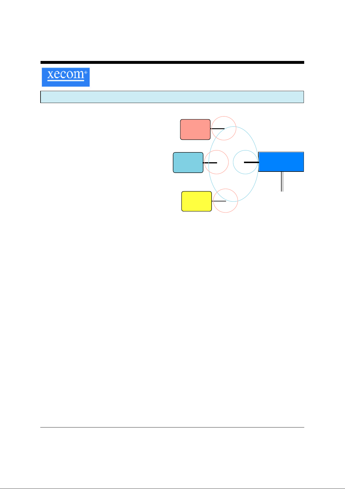
System A
XE900
Equipped
XE924
Base Access
Point
Dial-up
Telephone
Line
System B
XE900
Equipped
System C
XE900
Equipped
900MHz Base Access Network
Page 2
XECOM (2) XE924
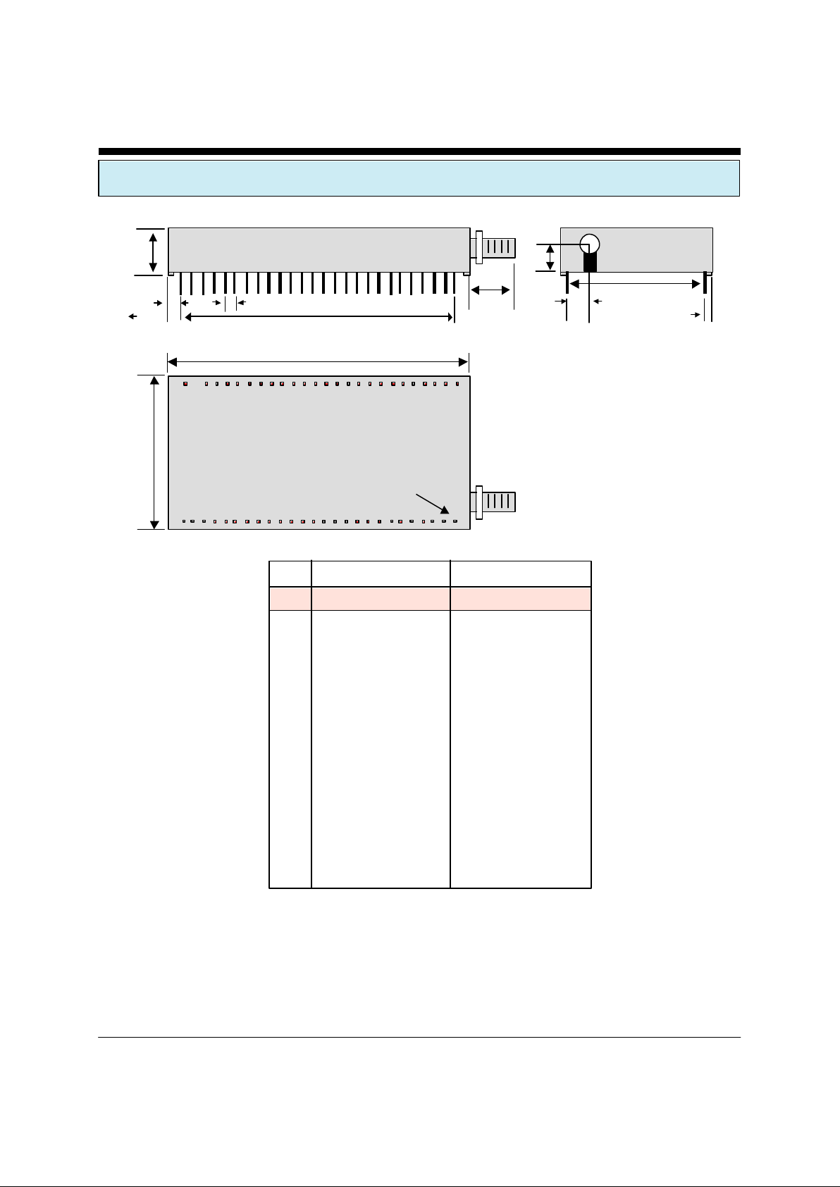
XE924 MECHANICAL SPECIFICA TIONS
Inches MM
PIN MIN MAX MIN MAX
A 2.740 2.760 69.60 70.10
B 0.550 0.560 13.97 14.22
C 1.370 1.390 34.80 35.31
D 5.300 0.510 13.46 12.95
E 2.490 2.510 63.25 63.37
F 0.090 0.110 2.29 2.79
G 0.115 0.135 2.92 3.43
H 1.190 1.210 30.23 30.73
J 0.130 0.150 3.30 3.81
K 0.220 0.240 5.59 6.10
L 0.300 0.320 7.62 8.13
Pin Description:
Pins are gold plated
Pin Dimensions .025 inches square, .minimum 0.120 inches long
A
B
C
D
E
FG
H
J
K
L
(Top View)
Pin 1
Page 3
XECOM (3) XE924
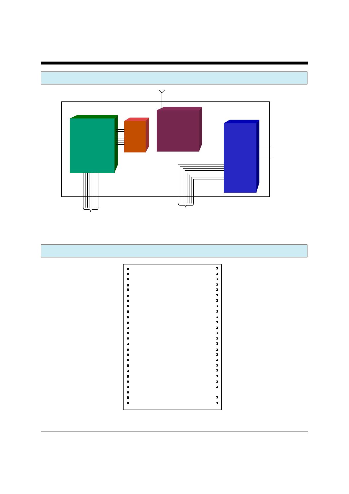
XE924 PIN CONFIGURATION
XE924 BLOCK DIAGRAM
1
2
3
4
5
6
7
8
9
10
11
12
13
14
15
16
17
18
19
20
21
22
23
24
25
26
52
51
50
49
48
47
46
45
44
43
42
41
40
39
38
37
36
35
34
33
32
31
30
28
27
XE924
RGND
RESERVED
RGND
RESERVED
RGND
RESERVED
RGND
RESERVED
RGND
RGND
RESERVED
RESERVED
RESERVED
VDD
DGND
/RST_VPP
VCC
RA3
/DSR
/MDM_DSR
RXD
/MDM_RXD
TXD
/MDM_TXD
/RI
/MDM_RI
RGND
RESERVED
RGND
RESERVED
RGND
RESERVED
RGND
RESERVED
RGND
RGND
RF_PDN
RF_TXDATA
RF_RXDATA
RGND
/CTS
/MDM_CTS
/DCD
/MDM_DCD
/DTR
/MDM_DTR
/RTS
RESERVED
RESERVED
TIP
RING
Comm
Controller
ROM
2400 BPS
MODEM
Tip
Ring
900 MHz
Transceiver
Antenna
Modem
Serial IF
Communications
Controller
Serial IF
Page 4

XECOM (4) XE924
XE924 PIN CONFIGURATION
SIGNAL PINS DESCRIPTION
RGND 1, 3, 5, 7, 9, 10, RFGND provides the common reference point for all high
39, 43, 44, 46, frequency signals.
48, 50, 52
RESERVED 2, 4, 6, 8, 11,12, These pins are reserved for future use. No connections
13, 30, 31, 45 should be made to these pins.
47, 49,51
VDD 14 VDD provides power to the 900 MHz transceiver.
DGND 15 DGND provides the ground reference for the modem and
communications controller circuitry in the XE924.
/RST_VPP 16 RST_PV provides a hardware reset line for the XE924’s
communications controller.
VCC 17 VCC provides power to the communications controller and
modem circuitry.
RA3 18 Programmable I/O pin from the embedded communications
controller.
/DSR 19 /DSR is the Data Set Ready input to the communications
controller. This pin is normally tied to /MDSR, pin 20
/MDSR 20 /MDSR supplies the Data Set Ready output from the modem.
/MDSR is an active low output. This pin is normally tied to
/DSR, pin 19.
RXD 21 RXD is the serial data input to the communications controller.
This pin is normally tied to /MRXD, pin 22.
/MRXD 22 /MRXD is the serial data output from the modem in the
XE924. A Mark condition on /MRXD is active low. This pin
is normally tied to RXD, pin 21.
TXD 23 TXD is the serial data output from the communications
controller. It is normally tied to /MTXD, pin 24
/MTXD 24 /MTXD is the serial data input to the modem in the XE924. A
Mark condition on /MRXD is active low. TXD is normally tied
to /MTXD, pin 23
/RI 25 /RI provides the Ring Indication input to the communications
controller. /RI is normally tied to Pin 26
Page 5

XECOM (5) XE924
/MRI 26 /MRI supplies the Ring Indication output from the embedded
modem in the XE924. /MRI is active low. /MRI is normally
tied to Pin 26
RING 27 The Ring and Tip signals provide the connection from the XE924 to
the telephone line. FCC Part 68 Rules require a 1500 volt isolation
barrier between the telephone line and all other circuits. This isolation
must be preserved throughout the system.
UL60950 requires minimum creepage and clearances distances be
maintained between the Tip and Ring traces and all other circuits.
Clearance is the shortest distance between conductive circuits; creepage
is the distance between conductive surfaces along the surface.
TIP 28 The Ring and Tip signals provide the connection from the XE924 to the
telephone line. FCC Part 68 Rules require a 1500 volt isolation barrier
between the telephone line and all other circuits. This isolation must be
preserved throughout the system.
UL60950 requires minimum creepage and clearances distances be
maintained between the Tip and Ring traces and all other circuits.
Clearance is the shortest distance between conductive circuits; creepage
is the distance between conductive surfaces along the surface.
NO PIN 29 This pin is intentionally removed to improve the isolation from
the local telephone line.
RTS 32 /RTS supplies the Request to Send out put from the communi-
cations controller. /RTS is an active low output.
/MDTR 33 /MDTR connects to the modems Data terminal Ready line. It
is an active low input to the XE924. /MDTR is normally tied to
/DTR, pin 34.
/DTR 34 /DTR provides the Data Terminal Ready output from the
communications controller. /DTR is normally tied to /MDTR,
pin 33. This is an active low output.
/MDCD 35 /MDCD provides the Data Carrier Detect output from the
modem inside XE924. This is an active low output. /MDCD is
normally tied to /DCD, pin 36.
/DCD 36 /DCD is the Data Carrier detect input to the communications
controller. /DCD is normally tied to /MDCD, pin 35.
XE924 PIN CONFIGURATION
Page 6
XECOM (6) XE924
XE924 PIN CONFIGURATION
/MCTS 37 /MCTS provides the Clear to Send output from the modem
inside XE924. This is an active low output. /MCTS is normally tied to /CTS, pin 38.
/CTS 38 /CTS is the Clear to Send input to the XE924 communications
controller. /CTS is normally tied to Pin 37.
RF_RXDATA 40 RF_RXDATA serial data output from the 900 MHz transceiver
in the XE924. A Mark condition on RF_
RF_TXDATA 41 RF_TXDATA is the signal input to the 900 MHz transceiver in
the XE924. A Mark condition on RF_TXDATA is active high.
RF_TXDATA is normally tied to pin 12.
RF_PDN 42 RF_PDN placed the XE924’s 900 MHz transceiver into sleep
mode to reduce power consumption when not in use. It is an
active high signal. RF_PDN is normally tied Pin 11.
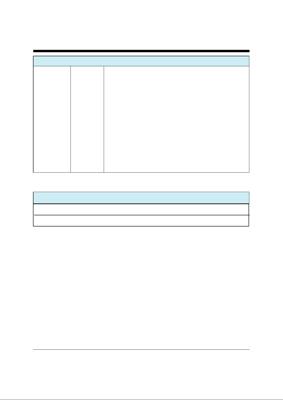
ABSOLUTE MAXIMUM RATINGS
Storage Temperature -25O C to +85O C
Operating Temperature Range
1
0O C to +70O C
1
Units may be screened for operation from -40 to +85C. An extra charge will be applied for this screening.
Page 7
XECOM (7) XE924
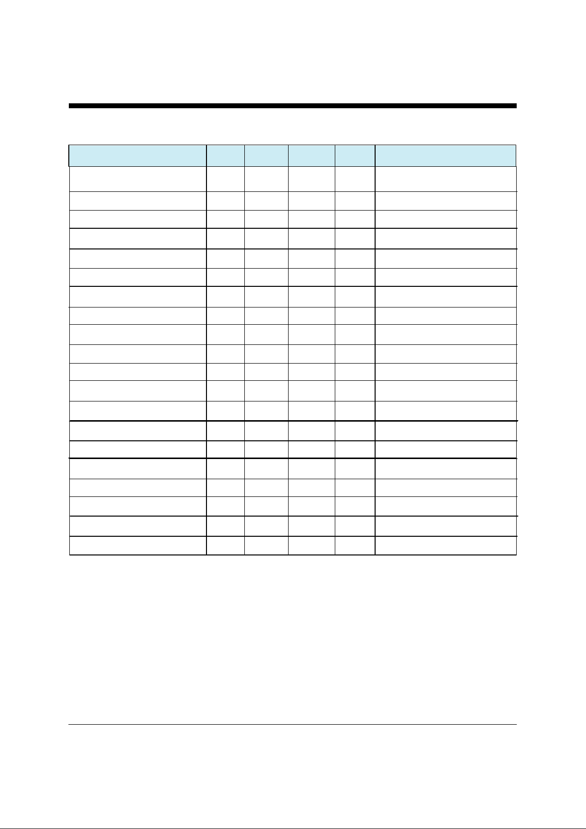
XE924 ELECTRICAL SPECIFICATIONS
VCC 4.75 5.0 5.25 Volts
ICC 325 ma Modem On Line
VDD 2.7 13 Volts
IDD 29 ma Transmit Mode
RF Carrier Frequency 916.43 916.48 916.53 MHz
Output Power -12 -10 -6 dBm 50 Ohm Load
Wireless Receive Sensitivity -94 dBm
Antenna Output 50 Ohms
RX to TX reversal 3 5 ms
TX to RX reversal 4 6 ms
Telephone Ring Sensitivity 38 150 VRMS Type B Ringer
Ring Frequency Detected 15.3 68 Hz Type B Ringer
Telephone Loop Current 10 40 100 ma
Line Impedance 600 Ohms
Data Transmit level -12 -10 -9 dBm
DTMF Transmit Level -2.5 0 dBm Avg over 3 second interval
Voh 2.4 Volts
Vol 0.4 Volts
Vih 2.0 VCC+0.3 Volts
Vil -0.3 0.8 Volts
Parameter Min Typ Max Units Comments
Page 8
XECOM (8) XE924
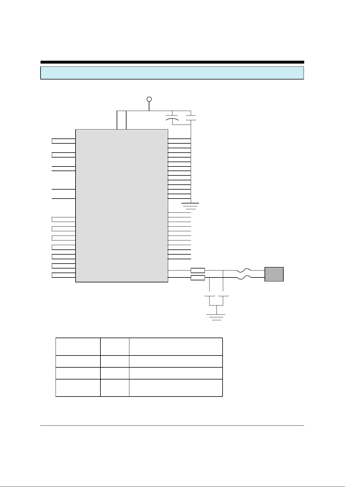
XE924 Typical Applicaiton Schematic
Parts List for Shared Line Feature Application Note
Reference
Designation Qty Description
C1, C2 2 Cap. 470 pfd 2600V
F1, F2 2 PTC, TR600-150
FB1, FB2 2 Ferrite, ACB2012L-120
XE924
RGND 52
RGND 50
RGND 48
RGND 46
RGND 44
RGND 43
RGND 39
RGND 10
RGND 9
RGND 7
RGND 5
RGND 3
RGND 1
DGND 15
Reserved 51
Reserved 49
Reserved 47
Reserved 45
Reserved 32
Reserved 31
Reserved 30
Reserved 8
Reserved 6
Reserved 4
Reserved 2
TIP 28
RING 27
16 RESET
18 RA3
40 RF_RXDATA
13 RESERVED
41 RF_TXDATA
12 RESERVED
11 RESERVED
42 RF_PDN
+5Volts
22uFd 0.01 uFd
RJ11 JACK
VDD 14
VCC 17
19 /DSR
20 /MDM_DSR
21 RXD
22 MDM_RXD
23 TXD
24 MDM_TXD
25 /RI
26 /MDM_RI
33 /MDM_DTR
34 /DTR
35 /MDM_DCD
36 /DCD
37 /MDM_CTS
38 /CTS
FB1
FB2
C1
C2
F1
F2
Antenna - Xecom recommends the Linx Technologies right angle antenna, ANT-916-CS-RCL-ND
Page 9

XECOM (9) XE924
XE924 COMMUNICATIONS CONTROLLER
Hardware:
A low-cost micro-controller performs the duties of the
communications controller in the XE924. This microcontroller manages the 900 MHz network and the data
translation between the 900 MHz transceiver and the
embedded modem.
The embedded modem is Xecom’s XE2420, 2400 BPS
modem. This modem includes its own dedicated
controller for the modem functions including the AT
commands. The serial interface signals from the
XE2420 are brought out to the XE924’s I/O pins for
diagnostic purposes.
900 MHz Network
The 900 MHz network controlled by the XE924
supports nodes on up to eight remote systems. All of
these systems communicate with the XE924 using
Xecom’s XE900 Smart Transceiver. the XE924 and
XE900 utilize a half-duplex channel on a single carrier
frequency, 916.48 MHz. The XE924 communications
controller manages this channel preventing collisions,
correcting errors, and reversing channels.
Carrier Sense Multiple Access (CSMA)
The primary tool used to prevent collisions between
systems is a CSMA protocol for each of the 900 MHz
transceivers. All XE900 and XE924 units in the
network listen for communications activity on the
916.48 MHz band before initiating a session.
Data Packets
The XE924 places all data incoming across the modem
link into packets. Likewise the XE900 places all of the
data arriving through its serial port into packets.
These packets providing addressing and error
correction for the wireless communications link. The
communications controllers in the XE900 and XE924
place the data in packets only for the wireless link. The
data is extracted from the packets before being sent to
the modem or to the XE900 serial port.
Wireless Link to Modem Link Translation
Data on the wireless link travels in packets at 9600 BPS.
The communications controller strips the data from the
packets before transmitting it through the modem.
Because the maximum data rate of the modem connection
is 2400 BPS, the communications controller buffers the
data, and sends it to the modem at 2400 BPS. While this is
happening any incoming data from the modem has to be
buffered and held until the wireless channel can be
reversed. When the wireless channel is available to
transmit, the data in the buffer is put into packets and
transmitted over the 900 MHz transceiver at 9600 BPS.
The communications controller also manages the modem’s
connections. AT commands entered at the remote node
are placed in packets and passed across the wireless link
by the XE900. The XE924 Communications Controller
removes the command from the packet, passes it to the
modem, and waits for a modem response. The modem
response is put in a packet and returned to the XE900
equipped node.
The routing of incoming modem calls will also be handled
by the communications controller. After the modem
answers the incoming call and establishes the
connection, the XE924 Communications Controller waits
for entry of the desired node address before directing the
call to the proper node.
Page 10

XECOM (10) XE924
XE924 EMBEDDED MODEM
The modem embedded in the XE924 is Xecom’s XE2420
modem. The XE2420 includes FCC Part 68 Registration.
This registration can be applied to user equipment
without additional certification testing.
Modem Control
Industry standard AT Commands perform the control and
configuration of the embedded modem. To change
modem configuration or to initiate call, the remote node
on the 900 MHz network sends the desired AT commands
across the wireless link as data. The XE924
communications controller passes the AT commands to
the modem where they are executed. The modem
responses are returned across the wireless link to the
remote node.
Command Line Format
Command lines issued to the modem follow a strict
format. Each command begins with the prefix AT and
ends with a Carriage Return. The XE924 communications
controller sends all commands to the embedded modem
at 2400 BPS. The modem uses the AT command prefix to
automatically determine the parity of the incoming
characters.
Command Prefix - Each command, except the A/
command, begins with the AT prefix. The "A" and "T"
may be either both upper case or both lower case but
cannot be of different cases. The prefix identifies the
speed and parity of the commands sent to the modem by
the host. Speed is determined by measuring the width of
the incoming bits. Parity is determined by comparing the
parity bit of the "A" and the "T."
Command Line - Commands may be strung together in a
single command line of up to 36 characters. The modem
executes the commands in the command string in the
sequence they appear. Spaces inserted into the command
line do not fill space in the modem’s command buffer. A
Carriage Return terminates the command line and causes
the commands to be executed. Register S3 allows the user
to select a character other than a Carriage Return to
terminate the command line.
Re-Execute Last Command - The A/ command reexecutes the last command line. This is the only command
which does not require the "AT" prefix.
Omitted Parameters - Most commands include a
parameter which determines the function setting. When
the command parameter is omitted from the command
string, it is assumed to be a 0.
Result Codes - The modem normally issues a result code
after each action. Result codes may be provided as full
words, one or two digit numeric codes, or may be
disabled. Each result code ends with a Carriage Return
when numeric result codes are chosen. When full word
result codes are chosen, a Line Feed and Carriage Return
precede and follow each result code.
Escape Sequence - A specific character repeated three
times ins succession switches the modem from data mode
to command mode. The character used in this sequence is
defined by register S2. The default sequence is “+++.”
An AT Command must be entered within the period
defined by S12 to complete the switch to command mode.
Page 11

XECOM (11) XE924
Embedded Modem AT Commands
An asterisk indicates the factory default
A - Answer Command - forces the modem to go off-hook in
answer mode
Bn - Select Communications Standard
n=0 Selects CCITT standards
n=1 Selects Bell standards*
n=2 Selects V.23/Bell 202 (see S37)
D - Dial Command -
0-9, A-D, #, * = Dialing Digits
P = Pulse dial
T = Tone dial
R = Connect as an answering modem
W = Wait for dial tone
, = Pause for the duration of S8
@ = Wait for silence
! = Switch hook flash
; = Return to the command state
S=n = Dial Stored Number n
En - Command Echo
Enabling the command echo on the embedded modem will
reduce the efficiency of the wireless link and is not
recommended
Hn - Switch Hook Control -
n=0 Switch hook relay opens
n=1 Switch hook relay closes
In - Modem Identification
On - On Line
n=0 Return On Line with no retrain*
n=1 Initiate retrain while returning On line.
Qn - Responses
n=0 Send responses *
n=1 No Responses
Sr? - Interrogate Register Sr=n - Set Register Value -
Vn - Result Codes -
n=0 Numeric Result Codes
n=1 English Word Result Codes*
Xn - Result Code Set -
n=0 Responses 0-4
n=1 Responses 0-5 & 10
n=2 Responses 0-6 & 10
n=3 Responses 0-5, 7 & 10
n=4 Responses 0-7 & 10*
&F - Reset Factory Defaults
&Gn - Guard Timer -
n=0 None *
n=1 550 Hz Guard Timer
n=2 1800 Hz Guard Timer
%En - Automatic Retrain
n=0 Automatic Retrain Disabled
n=1 Automatically retrain on poor signal quality *
\Nn - Data Buffering
n=0 Data Buffered
n=1 Direct Mode no data buffering *
Page 12

XECOM (12) XE924
Embedded Modem Registers
S0 Answer on nth Ring: S0 sets the modem to
automatically answer on the nth ring. Setting S0 to 0
disables automatic answer.
Range: 0 to 255
Units Rings
Default 0
S1 Ring Count: S1 is a read-only register showing the
number of rings detected. If a ring is not detected
within 8 seconds, S1 is reset to zero.
Range: 0 to 255
Units Rings
Default 0
S2 Escape Character: S2 determines the ASCII escape
character. Values of 0-127 select valid ASCII escape
characters; values from 128 to 255 disable the escape
sequence.
Range: 0 to 255
Units ASCII Character
Default 43 (+)
S3 Line Termination Character: S3 determines the
ASCII character which will terminate commands and
modem responses.
Range: 0 to 127
Units ASCII Character
Default 13 (Carriage Return)
S4 Line Feed Character: S4 sets the ASCII character
to act as a line feed character in modem responses.
Range: 0 to 127
Units ASCII Character
Default 10 (Line Feed)
S5 Backspace Character: S5 defines the ASCII
character used as a backspace to edit the command
line.
Range: 0 to 127
Units ASCII Character
Default 8 (Back Space)
S6 Dial Tone Wait Time: S6 determines how long the
modem waits for dial tone before dialing begins. The
Dial Tone Wait Time cannot be set to less than two
seconds.
Range: 2 to 255
Units Seconds
Default 2
S7 Wait for Carrier after Dialing: S7 determines how long
the modem waits for a valid carrier signal after dialing is
completed.
Range: 1 to 255
Units Seconds
Default 30
S8 Comma Pause Time: S8 defines the duration of the
pause initiated by a comma in the dialing string. The pause
is generally used when waiting for a second dial tone.
Range: 1 to 255
Units Seconds
Default 2
S9 Carrier Detect Response Time: S9 establishes the
length of time the remote modem's carrier must be present
to be recognized as valid.
Range: 1 to 255
Units 0.1 Seconds
Default 6
S10 Carrier Off Disconnect Delay: S10 selects how long
carrier must be lost before the modem disconnects. Note:
If S10 is smaller than the value of S9 or S10 is set to 255,
the modem will not automatically disconnect on loss of
carrier.
Range: 1 to 255
Units 0.1 Seconds
Default 14
S11 Tone Dialing Speed: S11 sets the duration and spacing
of the dialing tones. S11 does not affect the pulse dialing
rate.
Range: 50 to 255
Units 1 Millisecond
Default 95
S12 Escape Code Guard Timer: S12 sets the escape
sequence guard timer. If characters are received before or
after the escape sequence, within the guard timer, the
modem aborts the escape attempt and remains in data
mode.
Range: 0 to 255
Units 0.02 Seconds
Default 50
Page 13
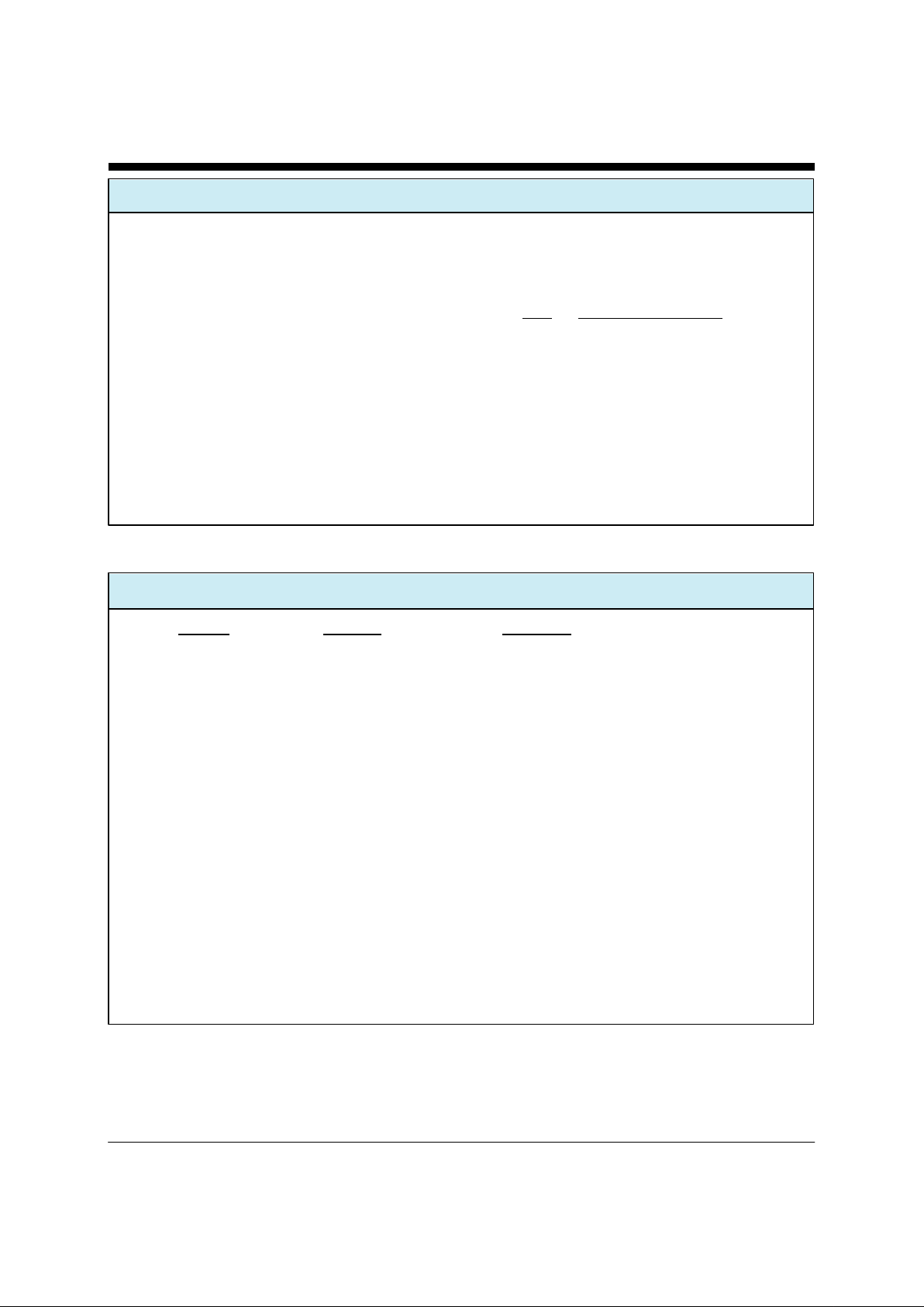
XECOM (13) XE924
Embedded Modem Registers continued
S28 Inactivity Timer: S28 determines how long the mo-
dem will remain on line with not data flowing. A 0 in
this register disables the inactivity time out.
Range: 0-255
Units Minutes
Default 0
S29 Hook Flash Time: S29 determines the amount of
time the modem will go on-hook when a hook switch
flash is called for.
Range: 0-255
Units 0.02 Seconds
Default 25
S37 Maximum Line Data Rate: S37 sets the maximum
line data rate or modulation technique that the modem
will support for any connection.
Register
Value Communications Supported
0 Maximum Data Rate determined by the
autobaud function of the AT Command
1 Connect using V.23, asymmetrical modem
modulation, 1200/75 BPS
2 Connect using Bell 202, asymmetrical
modulation, 1200/150 BPS
3 V.21, Bel 103, 300 BPS
4 Reserved
5 V.22, Bell212A 1200 BPS
6 V.22bis 2400 BPS
Embedded Modem Responses
Numeric Full Word Description
0 OK Successfully executed command line
1 CONNECT 300 bps connection
2 RING Ring signal detected
3 NO CARRIER Carrier not detected/lost
4 ERROR Error in command line
5 CONNECT 1200 1200 bps connection
6 NO DIAL TONE No dial tone detected
7 BUSY Busy signal detected
8 NO ANSWER 5 second silence not detected
10 CONNECT 2400 2400 bps Connection
16 CONNECT 1200TX/75RX V.23 Connection transmitting at 1200 BPS
17 CONNECT 75TX/1200RX V.23 Connection transmitting at 75 BPS
18 CONNECT 1200TX/150RX Bell 202 Connection transmitting at 1200 BPS
19 CONNECT 150TX/1200RX Bell 202 Connection transmitting at 150 BPS
Page 14

XECOM (14) XE924
Interface
When a communications are intiated from the remote
modem, the XE924 switches to its wireless AT commands
after the modem connection is established. These AT
commands control the configuration of the wireless link.
Command Line Format
Wirelesss Command lines issued to the XE924 follow the
same format as those of the modem AT commands Each
command begins with the prefix AT and ends with a
carriage return. All AT commands are issued to the
communications controller at the modem data rate; there
is no autobaud function. The modem uses the AT
command prefix to automatically determine the parity of
the incoming characters.
Command Prefix - Each command, except the A/
command, begins with the AT prefix. The "A" and "T"
may be either both upper case or both lower case but
cannot be of different cases. The prefix identifies parity of
the commands by comparing the parity bits of the "A"
and the "T" characters.
Command Line - Commands may be strung together in a
single command line of up to 36 characters. Commands in
the command string are executed in the sequence they
appear. Space inserted into the command line do not fill
AT COMMANDS FOR 900 MHZ TRANSCEIVER
space in the modem’s command buffer. A carriage return
terminates the command line and causes the commands to
be executed. Register S3 allows the user to select a
character other than a carriage return to terminate the
command line.
Re-Execute Last Command - The A/ command reexecutes the last command line. This is the only command
which does not require the "AT" prefix.
Omitted Parameters - Most commands include a
parameter which determines the function setting. When
the command parameter is omitted from the command
string, it is assumed to be a 0.
Result Codes - The modem normally issues a result code
after each action. Result codes may be provided as full
words, one or two digit numeric codes, or may be
disabled all together. Each result code ends with a
carriage return when numeric result codes are chosen.
When full word result codes are chosen, a Line Feed and
Carriage Return precede and follow each result code.
Disconnect Sequence - A three character sequence
initates a disconnect of the wireless link. The sequence
“~~~” is assigned to disconnect the link.
Page 15

XECOM (15) XE924
Embedded Modem AT Commands
An asterisk indicates the factory default
A Answer Command - forces the smart transceiver
respond to a summons from another wirless device.
Dn Initate a Wireless Link - attempts to establish a
connection with the transceiver at address n.
In Identification - displays product identificaton code.
n=0 Display Product Code
n=1 Display Product Name
n=2 Display Model Number
n=3 Display Copywrite
n=4 Display Firmware Revision
Qn Result Code Display - determines if results codes
will be displayed.
n=0 Display Result Codes *
n=1 Do not Display Result Codes
Sn= Set Value of Register Sn
Sn=? Read Value of Register Sn
Vn Response Type - selects Full Word or Numeric
responses
n=0 Numeric Responses
n=1 Full Word Responses *
Zn Reset - executes a soft Reset
n=0 Reset to Values Stored in User Profile 0 *.
n=1 Reset to Values Stored in User Profile 1
&F Restore Factory Settings - returns all configuration
commands and registers to their factory default values.
&V View Active Configuration - sends the active
configuration data to the system host.
&Wn Store Current Configuration - loads the current
XE900 configuration into either User Profile 0 or User
Profile 1.
n=0 load configuration into User Profile 0
n=1 load configuration into User Profile 1
#B Wireless Broadcast Mode - intiates wireless
boradcast mode for diagnostic purposes.
#ID= Set ID Value for the XE900
#ID=?Read ID Value from the XE900
#Ln Check RSSI Level - Displays current Wireless
recevied signal levels
n=0 Display a single value *
n=1 Display 4 Values
n=2 Display continuous values
Page 16
XECOM (16) XE924
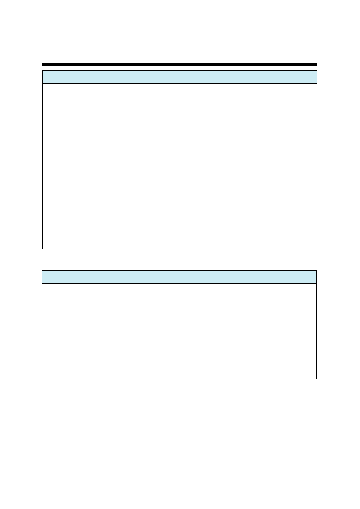
Wireless Configuration Registers
S0 Answer Wireless Link Request: S0 determines if
the XE900 will automatically respond to a wireless
link request.
S0=0 No Automatic response to link requests
S0=1 Automatically respond to link requests
S2 Wireless Disconnect Character - S2 sets the ASCII
character to be used in the link disconnect sequence.
The defaule character is the tilde “~”.
Range: 0-255
Default: 126
S12 Disconnect Guard Timer - S12 sets the value of the
guard timer in milliseconds before and after the
disconnect sequence. If any characters other than the
disconnect sequence are received within the window
defined by S12 the llink will not be disconnected.
Range: 0-255
Default: 40
Units: Milliseconds
S14 Bit-mapped Register - S14 stores the values of the ATE,
ATQ and ATV commands.
S105 XE900 ID Number - S105 sets the ID number for the
XE900. Each unit on the Base Access Network is
required to have a unique ID number. The ID number of
the Base Access Point is always 1.
Range: 2-254
S106 Set Noise Threshold - S106
Wireless Responses
Numeric Full Word Description
0 OK Successfully executed command line
1 CONNECT RF Wireless Connection Established
2 RING Wireless Link Request Detected
3 DISCONNECT Failed to Establish or Lost Wireless Link
4 ERROR Error in command line
7 BUSY Link Request Time Out has occurred
9 WAIT Wireless Link is not available
Page 17

XECOM (17) XE924
FCC Part 68 Instructions
The information shown below must appear in the users manual for the system in which the XE924 is used.
The XE2420 used in the XE924 complies with part 68 of the FCC Rules and Regulations. With each device shipped, there is a label
which contains, among other information, the FCC Registration Number and Ringer Equivalence Number (REN) for this product.
You must, upon request, provide this information to your telephone company.
The mounting of this device in the final assembly must be made in such a manner as to preserve the high voltage protection between
the TIP/RING Connection and the rest of the system. Typically, this may be accomplished by maintaining a minimum spacing 100
mils between the TIP/RING Traces to the RJ-11C Jack and low voltage portion of the system. No additional circuitry may be attached between TIP/RING and the telephone line connection, unless specifically allowed in the rules.
The REN is useful to determine the quantity of devices you may connect to a telephone line and still have all of these devices ring
when the number is called. In most, but not all areas, the sum of the RENs of all devices connected to one line should not exceed
five (5.0). To be certain of the number of devices you may connect to the line, as determined by the REN, you should contact the local telephone company to determine the maximum REN for you calling area.
If your system causes harm to the telephone network, the telephone company may discontinue service temporarily. If possible, they
will notify you in advance. If advance notification is not practical, you will be notified as soon as possible.
Your telephone company may make changes in its facilities, equipment, operations or procedures that could affect proper functioning
of your equipment. If they do, you will be notified in advance to give you an opportunity to maintain uninterrupted telephone service.
If you experience trouble with this device, please contact XECOM at (408) 945-6640 for information on obtaining service or repairs.
The telephone company may ask you to disconnect this device from the network until the problem has been corrected or until you
are sure that the device is not malfunctioning.
The device may not be used on coin service lines provided by the telephone company (this does not apply to private coin telephone
applications which use standard telephone lines). Connection to party lines is subject to state tariffs.
FCC Part 68 Registration
Below is the FCC Part 68 Registration information on the XE2420 modem used in the XE924. This information
must appear on the outside of the system in which the XE924 is used.
Xecom, Inc.
Model XE2420
Made in USA
FCC Registration Number: DWEM509BMD-E
Ringer Equivalence: 0.9B
Page 18

XECOM (18) XE924
FCC Part 15 Compliance
The XE924 is designed to comply with FCC Part 15 rules, however, it is not FCC approved. The XE924 is not eligible
for FCC approval because it is a component which requires the addition of other components to function. These
other components include the power supply, antenna, and printed circuit board. Any of these other components
could affect FCC Part 15 compliance if not properly designed.
Approvals may be required of your system before it can be sold in the united States or other countries. The XE924 is
subject to rules governing both intended and unintended radiation. The 900 MHz transceiver must transmit its signal
in compliance with FCC Part 15 rules governing intended radiation. Part 15 rules also govern unintended radiation
sources such as the Telephone line cable connected to the XE924. Your system will have to be approved before it
can be sold; however, because the XE924 utilizes the 900 MHz ISM band, your customers will not require an FCC
license.
Page 19

XECOM (19) XE924
Devices sold by XECOM are covered by the warranty provisions appearing in its Terms of Sale only. XECOM makes no warranty,
express, statutory, implied, or by description regarding the information set forth herein, or regarding the freedom of the described devices from patent infringement. XECOM makes no warranty of merchantability or fitness for any purposes. XECOM reserves the
right to discontinue production and change specifications and prices at any time and without notice. This product is intended for use
in normal commercial applications. Applications requiring extended temperature range, unusual environmental requirements, or high
reliability applications, such as military, medical life-support or life-sustaining equipment, are specifically not recommended without
additional processing and authorization by XECOM for such application.
Xecom assumes no responsibility for the use of any circuitry other than circuitry embodied in a Xecom product. No other circuits,
patents, or licenses are implied.
Xecom's products are not authorized for use as Critical Components in Life Support Devices or Systems.
Life Support Devices or Systems are devices or systems which, (a) are intended for surgical implant into the body, or (b) support
or sustain life, and whose failure to perform, when properly used in accordance with instructions provided in the labeling, can be reasonably expected to result in significant injury to the user.
A Critical Component is any component of a life support device or system whose failure to perform can be reasonably expected
to cause failure of the life support device or system, or to affect its safety or effectiveness.
Terms of Sale
Life Support Policy
Copyright, Xecom © 2002
While Xecom, Inc. has made every effort to ensure that the information presented here is accurate, Xecom will not be liable for any damages arising from errors or
omission of fact. Xecom reserves the right to modify specifications and/or prices without notice. Product mentioned herein are used for identification purposes
only and may be trademarks and/or registered trademarks of their respective companies.
Xecom Incorporated
374 Turquoise Street, Milpitas, CA 95035
Ph:408-945-6640 Fax:408-942-1346 E-Mail: [email protected]
 Loading...