

Page 1
XECOM XE0080
Surface Mount V.34 Telephone Line Interface
xecom
XE0080
9-97
TM
Description
Xecom's XE0080 is a miniature, surface-mount
telephone interface module for high-volume
applications. The XE0080 meets FCC Part 68
rules for direct connection to the public telephone
network, supports V.34 data transfer, and adapts
to automated pick and place equipment.
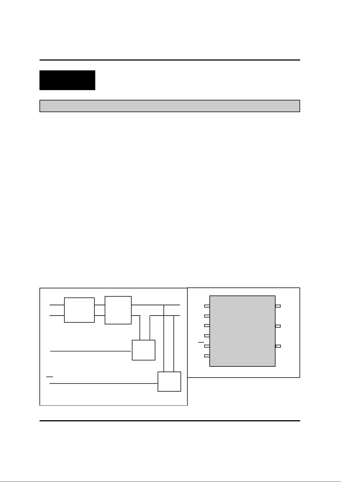
The XE0080 is a complete telephone line
interface. It includes the line transformer, ring
detection, switch hook control and loop current
holding circuit. The XE0080 supplies a 1500 volt
isolation barrier between the telephone line and
the host circuitry.
The XE0080 fits all this circuitry into a package
just 0.80 inches square and 0.200 inches thick.
The 0080 attaches to the board through nine
surface-mount pins.
The XE0080 operates from a single power supply
of either +5 volts or +3.3 volts for low power
applications. It is intended for high volume
applications including set top box and credit
verification systems
Features
* Miniature Size: 0.8" long, 0.8" wide, and 0.2"
thin (maximum);
* 9-pin Surface mountable package;
* Supports V.34 data transfer to 28,800 bps;
* FCC Part 68 Compliant;
* Low Total Harmonic Distortion -80 dB max.;
* Ring Detection;
* 3.3 Volt or 5 Volt Operation
* Hookswitch Control
Block Diagram PIN CONFIGURATION
1 (top view) 9
2
3 8
4
5 7
6
Gnd
T2
OH
T1
RI
Vcc
Tip
Ring
N/C
Loop
Current
Holding
Circuit
Line
Transformer
Hook-
Switch
Ring
Detect
Tip
Ring
T1
T2
OH
RI
Page 2
XECOM (2) XE0080
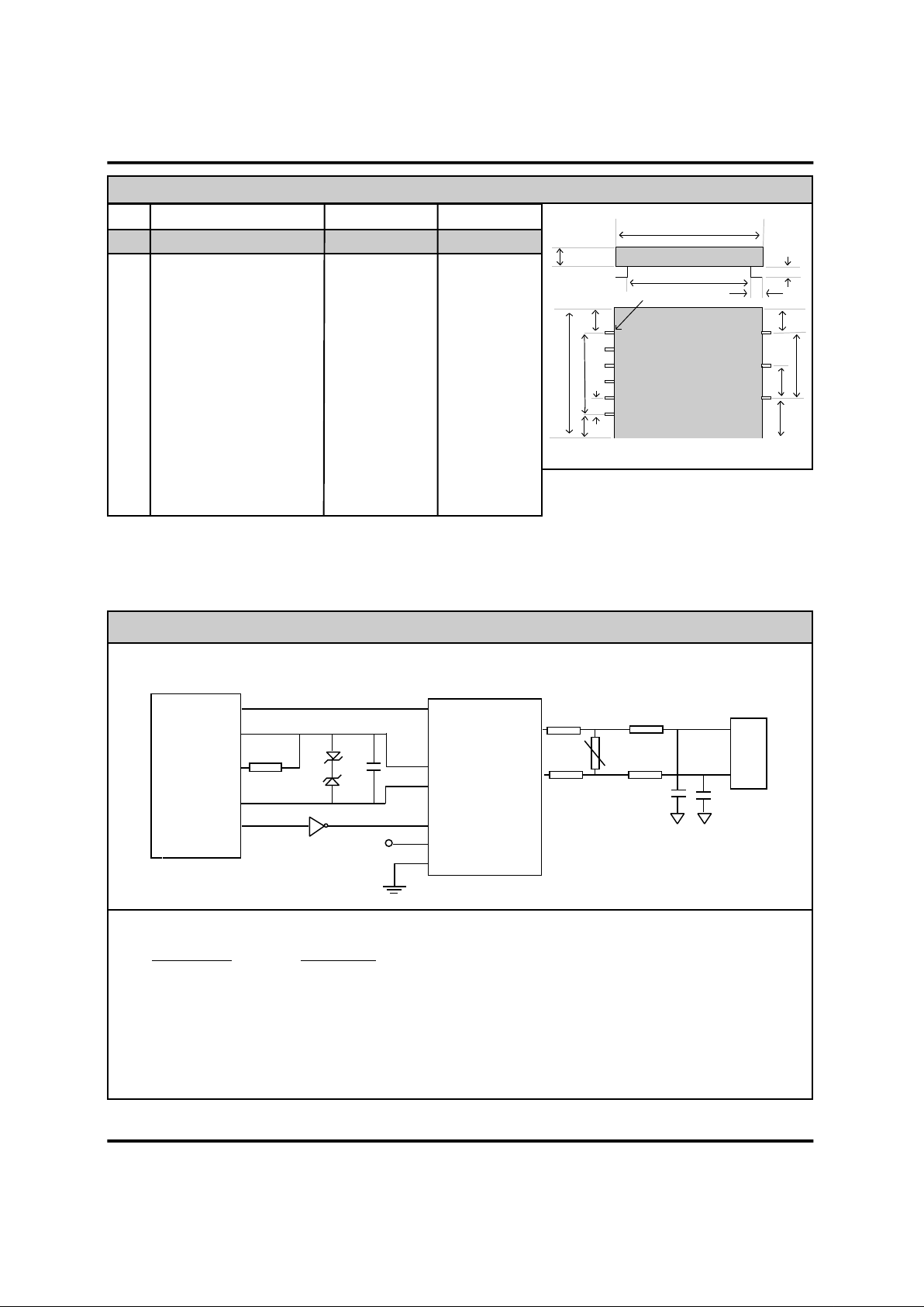
XE0080 Mechanical Specifications
A
B
C
D
E
G
F
H
J
I
Pin 1
F
F
K
L
A Module Width 0.770 0.780 19.56 19.81
B Module Height 0.195 0.205 4.95 5.21
C Pin Length 0.035 0.045 0.89 1.14
D Pin Row Length (6 to 9) 0.395 0.405 10.03 10.29
E Module Length 0.750 0.760 19.05 19.30
F End of Row to edge 0.130 0.140 3.30 3.56
G Pin 7 to module edge 0.220 0.230 5.59 5.84
H Pin Spacing (control side) 0.095 0.105 2.41 2.67
I Pin Spacing (Telco side) 0.195 0.205 4.95 5.21
J Pin Row Length (1 to 5) 0.495 0.505 12.57 12.83
K Row to Row Spacing 0.620 0.630 15.75 16.00
L Horizontal Pin Length 0.075 0.085 1.90 2.16
Inches Millimeters
Dim Description Min Max Min Max
Note: Xecom placed the telephone and control leads on opposite sides of the device to assist the user in
maintaining the necessary isolation between the telephone network and the user equipment. FCC Part 68 rules
require 1500 volts isolation between the telephone line and all other circuits.
XE0080 Typical Connection Diagram For Rockwell RC224ATL
RJ11
+5 Volts
TXA1
RXA
TXA2
Rm
Z1
Z2
C1
MOV1
C2
FB1
FB2
C3
3
4
Rockwell
RC224ATL
Ring -
OHRELAY -
XE0080
Tip 9
Ring 8
4 T1
2 T2
5 /RI
3 OH
6 Vcc
1 Gnd
15 ohms
15 ohms
Recommended Parts
Designation Description
Rm Line Impedance Matching Resistor, 300 ohms, 5%
C1 .01 microfarad
C2, C3 47 picofarad, 3000 Volts (Sprague Part Number 30GA-T47)
Z1, Z2 Zener Diode 4.3 Volts
FB1, FB2 Ferrite Beads (TDK Part Number CB30-453215B)
MOV1 Minimum Breakover 220 volts (Teccor Part Number P2600BA70)
Page 3

XECOM (3) XE0080
PIN NAME DESCRIPTION
1 GND Ground connection to the XE0080. This signal provides the reference for the OH
output and RI input. This pin should be connected to the system's digital ground.
2 T2 T2 in conjunction with T1 provides the differential input/output for the analog signal. T2
connects directly to the secondary of the embedded line transformer. To match the
impedance of the 600 ohm telephone line, a 340 ohm resistor is required on T1 or T2.
3 OH OH is an active high input controlling the modem hook switch. Activating OH closes
the hook-switch causing the XE01080 to seize the local telephone line. The telephone
line connection is dropped when OH is deactivated.
You may use OH to simulate rotary dialing. Closure of the hook-switch generates
dialing pulses, one pulse for the digit one to ten pulses for the digit zero. The correct
pulse rate is ten pulses per second. The pulses must be asymmetrical with the hookswitch closed for thirty-one milliseconds and open for sixty-nine milliseconds. A pause
of at least one hundred milliseconds must be observed between digits.
4 T1 T1 in conjunction with T2 provides the differential input/output for the analog signal. T1
connects directly to the secondary side of the line transformer embedded into the
XE0080. To match the impedance of the DAA to the 600 ohm telephone line, a 340
ohm resistor is required on T1 or T2.
5 \RI Ring Indicate is an active low output. RI active indicates the presence of an incoming
call. RI provides a square wave representation of the Ring signal present across Tip
and Ring. This permits intelligent monitoring of the ring signal. The XE0080
recognizes ring voltages of thirty-eight to one hundred fifty volts RMS in the frequency
range of sixteen to sixty-eight Hertz.
6 VCC +5 Volt power source for the XE01080. VCC powers the RI and OH control lines.
7 N/C No Connect
8 Ring Ring is one wire of the two-wire telephone line connection (RJ11 Pin 4). FCC Part 68
Rules require a 1500 volt isolation barrier between the telephone line and all other
circuits. This isolation must be preserved throughout the system. Xecom recommends
0.100 inch spacing between traces connected to Ring and all other conductors to
preserve this isolation.
9 Tip Tip is one wire of the two-wire telephone line connection (RJ11 Pin 3). FCC Part 68
Rules require a 1500 volt isolation barrier between the telephone line and all other
circuits. This isolation must be preserved throughout the system. Xecom recommends
0.100 inch spacing between traces connected to Tip and all other conductors to
preserve this isolation.
The telephone company places a DC "Battery" voltage across Tip and Ring on all
public switched telephone lines. The XE0080 accept this line battery voltage without
regard to its polarity.
PIN DESCRIPTIONS
Page 4
XECOM (4) XE0080
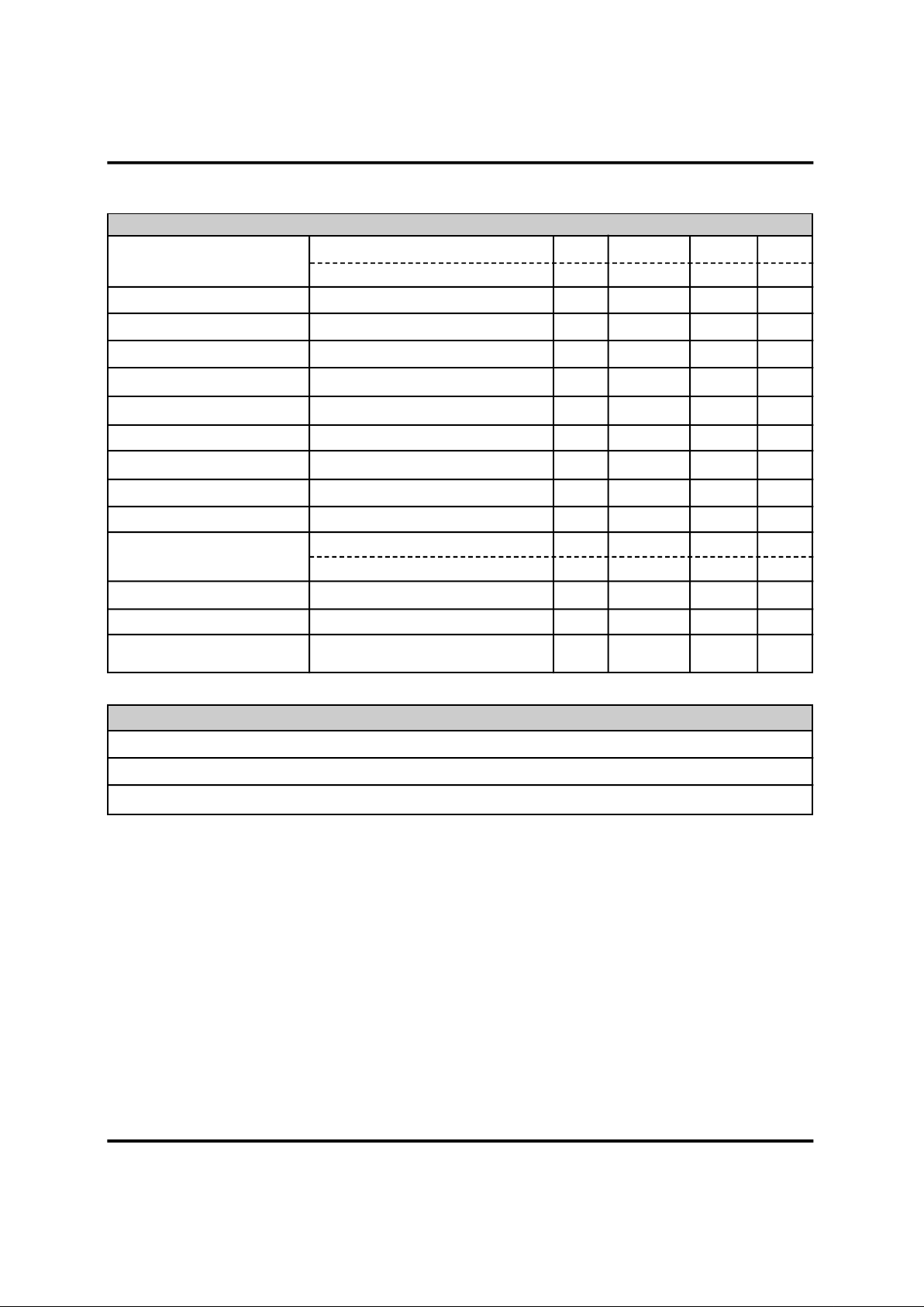
ABSOLUTE MAXIMUM RATINGS
Storage Temperature -25OC to +85OC
Operating Temperature Range 0OC to +70OC
Maximum Lead Temperature (soldering 2 seconds per wave) 260OC
Electrical Specification (Ta=0 to 70 deg C)
Power Supply Current Off Hook, 5.0 Volts 10 15 mA
Off Hook, 3.3 Volts 6.5 10 mA
Transmit Insertion loss 600 Ohm Impedence, 1000 Hz 1.7 2.7 3.7 dB
Receive Insertion loss 600 Ohm Impedance, 1000 Hz 1.7 2.7 3.7 dB
Line Impedance At 1000 Hz, Rm 590 ohms 540 600 660 Ohms
Coupler Matching Impedance Input impedence to T1 & T2 320 340 360 Ohms
Ring Detect Sensitivity AC voltage between Tip & Ring 38 150 Vrms
Type B ringer
Ring Detect Peak Current Ringing voltage of 40 Vrms 100 uA
Ring Detect Idle Current No Ringing Voltage present 10 uA
Ring Indicate Output Ring Voltage present 0.2 0.5 Volts
Hook Switch Control Voltage ON: (off-hook), VCC = 5 Volts 2.0 3.0 Volts
OFF: (on-hook) 0.2 0.5 Volts
Hook Switch Control Current VCC = 5 Volts 15 25 mA
Loop Current Off-Hook current draw from Line 20 100 mA
Total Harmonic Distortion At 1800 Hz, -9 dBm signal level -80 dBm
Parameter Conditions Min Typ Max Units
Page 5

XECOM (5) XE0080
Telephone Line Connection Information
A product to be connected to the telephone line must be approved by the appropriate governmental
agency. In the US this agency is the Federal Communications Commission (FCC); Industry Canada (IC)
performs this function in Canada. These agencies verify the product meets their country's specifications,
thereby protecting the telephone system from damage and protecting the user from high voltage
transients (such as lightning strikes) which may pass along the telephone line.
The XE0080 meets FCC Part 68 requirements for hazardous voltage, surge protection and leakage
current. If the system is to transmit data, fax, synthesized voice or DTMF tones, the user must certify that
the signals meet FCC requirements for maximum signal levels, out of band energy and billing delay. Full
details may be obtained from the FCC under Part 68 of the FCC Rules and Regulations, or in Title 47 of
the Code of Federal Regulations, however the basic requirements are as follows:
1. Maximum Transmit Level
“Permissive” telephone line, equipment which transmits data (such as a modem) must not exceed a
transmission level of -9 dBm.
2. Out of Band Energy
Data equipment must not transmit “out of band” energy on the telephone line which exceeds the following
limits:
Frequency Range Max. Power
200Hz to 3990Hz -9 dBm
3990Hz to 4005Hz -27 dBm
4005Hz to 16kHz -16 dBm
8kHz to 94kHz -47 dBm
86kHz to 270kHz -46 dBm
270kHz to 6MHz -6 dBm
3. DTMF Transmission Level
If the system is capable of DTMF dialing, the maximum DTMF transmission level must be less than 0
dBm averaged over a 3 second interval.
4. Billing Delay
A minimum delay of 2 seconds is required after the XE0080 is taken “off hook” and before any
information is transmitted. This delay ensures billing information may be exchanged without
interference.
For use in the United States the user of the XE0080 must register the final system under FCC Part 68.
This is generally accomplished through an independent testing lab which tests the System and submits
the proper paperwork to the FCC for Registration.
Page 6

XECOM XE0080
Copyright, Xecom © 1997
While Xecom, Inc. has made every effort to ensure that the information presented here is accurate, Xecom will not
be liable for any damages arising from errors or omission of fact. Xecom reserves the right to modify specifications
and/or prices without notice. Product mentioned herein are used for identification purposes only and may be
trademarks and/or registered trademarks of their respective companies.
X e com Incorporated
374 Turquoise Str eet , Mi lpitas, CA 95035
Ph:408-945-6640 Fax:4 08 -94 2 - 1 346 E-Mail [email protected]
Terms of Sale
Devices sold by XECOM are covered by the warranty provisions appearing in its Terms of Sale only. XECOM
makes no warranty, express, statutory, implied, or by description regarding the information set forth herein, or
regarding the freedom of the described devices from patent infringement. XECOM makes no warranty of
merchantability or fitness for any purposes. XECOM reserves the right to discontinue production and change
specifications and prices at any time and without notice. This product is intended for use in normal commercial
applications. Applications requiring extended temperature range, unusual environmental requirements, or high
reliability applications, such as military, medical life-support or life-sustaining equipment, are specifically not
recommended without additional processing and authorization by XECOM for such application.
Xecom assumes no responsibility for the use of any circuitry other than circuitry embodied in a Xecom product. No
other circuits, patents, or licenses are implied.
Life Support Policy
Xecom's products are not authorized for use as Critical Components in Life Support Devices or Systems.
Life Support Devices or Systems are devices or systems which, (a) are intended for surgical implant into the
body, or (b) support or sustain life, and whose failure to perform, when properly used in accordance with instructions
provided in the labeling, can be reasonably expected to result in significant injury to the user.
A Critical Component is any component of a life support device or system whose failure to perform can be
reasonably expected to cause failure of the life support device or system, or to affect its safety or effectiveness.
xecom
 Loading...