

Page 1
xecom
2400bps Serial Input Component Modem
XE2401L
02-13-96
Description
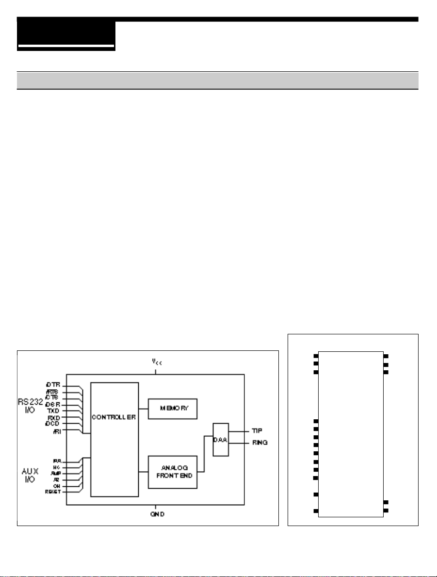
Xecom's XE2401L component modem is a
complete 2400 bps data modem. Its
compact size and TTL level, serial interface
allows for quick integration into virtually any
new or existing design. The XE2401L
contains all of the circuitry required for
complete modem operation, including a user
transferable FCC Part 68 registration,
allowing direct connection to the Telephone
Network. The XE2401L was specifically
designed to provide industrial systems
manufacturers with a complete, highly
integrated, compact solution for adding data
communication to their products.
Block Diagram
Features
• Small Size 1.08” x 2.28” x 0.42”,
• FCC Part 68 Registered, user transferable
• Data Transfer at 2400, 1200 and 300 bps
• Supported Protocols:
- CCITT V.22bis, V.22, V.21
- Bell 212A, 103
• TTL serial interface interfaces with
industry standard UART’s
• Single +5v supply
• Modem control with Industry standard “AT”
command set
• Standard package allows easy upgrades
to Fax (XE9624F) and 9600 bps (XE9601)
operation
PIN CONFIGURATION
Reset
AR
RXD
1 40
2 39
3 38
+5V
\DSR
\DCD
DTR\
AA\
CTS\
OH
TXD
RTS\
HS\
RI\
TIP
RING
(Top View)
9
10
11
12
13
14
15
16
18
20 21
22
AMP
GND
Page 2
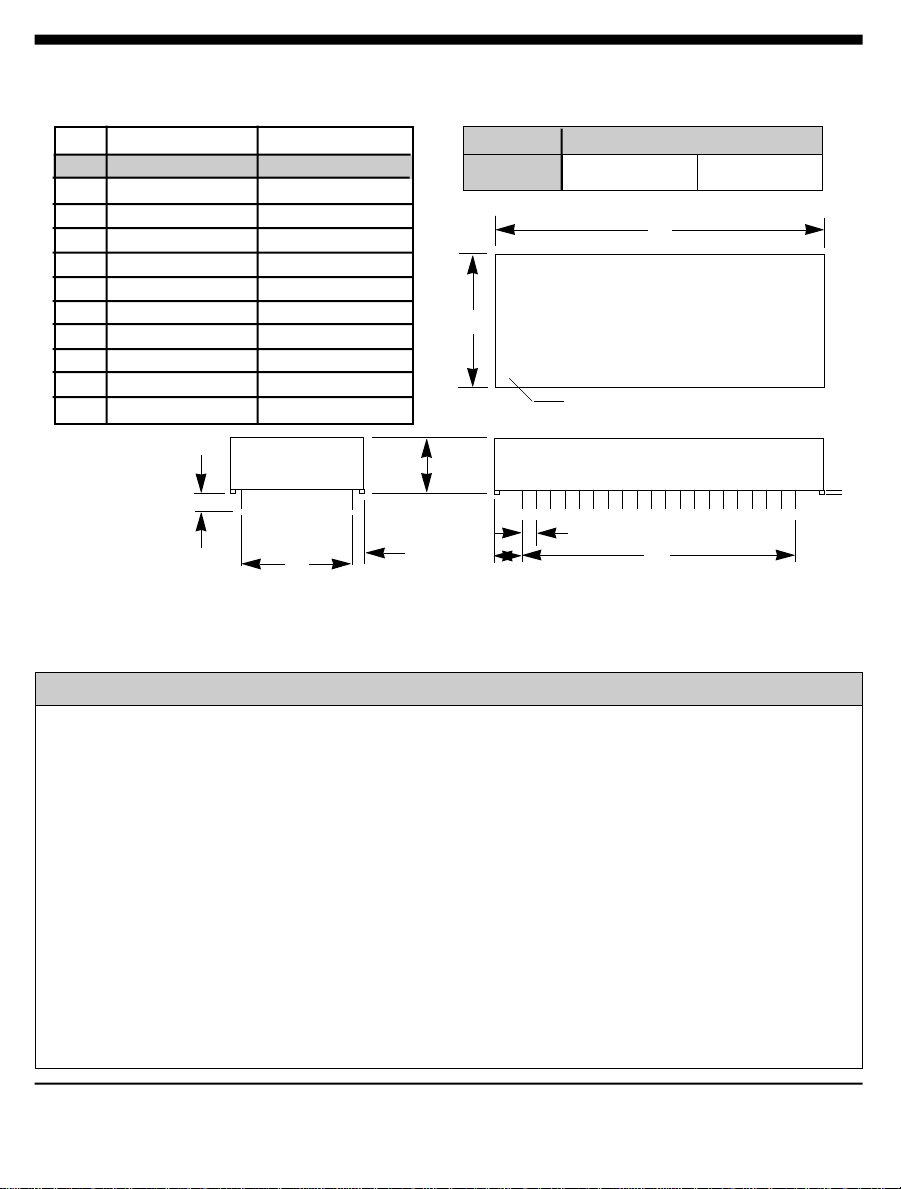
Mechanical Specifications - Package type 'C2'
INCHES METRIC(MM)
PIN MIN MAX MIN MAX
A 2.270 2.290 57.66 58.17
B 1.070 1.090 27.18 27.69
C 0.420 0.430 10.67 10.92
D 0.890 0.910 22.61 23.11
E 1.890 1.910 48.01 48.51
F 0.125 0.200 03.18 05.08
G 0.080 0.100 02.03 02.54
H 0.180 0.200 04.57 05.08
J 0.090 0.110 02.29 02.79
K 0.020 0.025 00.51 00.64
Pins: 0.025" x 0.025"
All pins tin-plated
Recommended hole
size: 0.056"
F
D
WEIGHT
B
•
C
G
H
METRIC ENGLISH
31.75 grams 1.12 oz.
PIN 1 DOT
J
Pin Descriptions
PIN NAME I/O DESCRIPTION
A
K
E
1 RESET I External reset pin active HI, TTL. An internal circuit resets the modem
when power is applied, no external reset is required. Any external reset
applied to the modem must be applied for a minimum of 100
milliseconds.
2 AR O Auxiliary Data/Voice Relay output, active HI, TTL/CMOS. When high the
external, auxiliary telephone set relay is closed and the modem is in the
voice mode.
3 RXD O Serial data output to the DTE (i.e. external UART). A logic "high"
represents a "mark" and a logic "low" represents a "space", TTL.
9 \DTR I Data Terminal Ready, input, active LO, TTL. The function of this pin
is set by the &D command and the value in register S21.
2/XECOM XE2401L
Page 3

PIN NAME I/O DESCRIPTION
10 \AA O Auto Answer enable indicator, output, active LO, TTL/CMOS.
11 \CTS O Clear to Send, output, active LO, TTL/CMOS. A low indicates the
modem is ready to accept data signals for transmission.
12 OH O Off-Hook, output, active HI, TTL/CMOS. A high indicates the modem's
hookswitch relay is closed connecting the modem to the telephone line.
13 TXD I Serial data input from the DTE (i.e. external UART). A logic "high"
represents a "mark" and a low represents a"space", TTL.
14 \RTS I Request to Send, input, active LO, TTL.
15 HS O High Speed indicator, output, active LO, TTL/CMOS. Low when
operating at 2400bps rate, high otherwise.
16 \RI O Ring Indicator, output, active LO, TTL. When low indicates the
modem is receiving a ring signal.
18 TIP --- Tip connection to the phone line (RJ11 pin3) from the internal DAA.
20 RING --- Ring connection to the phone line (RJ11 pin4) from the internal DAA.
Caution: Observe design rules for Tip & Ring trace layout.
21 GND --- Ground.
22 AMP --- Audio output to speaker. Function is determined by L & M commands
and the value in register S22. The imput impdedence to the speaker
driver must be greater tha 300 ohms.
38 \DCD O Data Carrier Detect, output, active LO, TTL/CMOS. Function is set by
the &C command and the value in register S21.
39 \DSR O Data Set Ready, output, active LO, TTL/CMOS. Function is set by the
&S command and the value in register S21.
40 Vcc --- +5 Volts.
Note: No other pin positions are present, i.e. only 18 physical pins are on this device.
No pins are present at positions 4, 5, 6, 7, 8, 17, 19, 23 - 37
XE2401L XECOM\3
Page 4

AT Commands
The XE2401L uses "AT" commands for
configuration and control. This section describes
use of the AT command format and lists the AT
commands, Registers and Result codes.
Modes of Operation
The "AT" commands have two operational
modes; Command Mode and Data Mode.
Data Mode: The XE2401L enters data mode
after it connects with a remote modem and issues
an appropriate "CONNECT" result code. In the
Data Mode the modem sends all data presented
on Transmit Data (TXD) to the remote modem
and puts data from the remote modem onto
Received Data (RXD). When the modem exits
data mode, it issues a "NO CARRIER" result
code.
Command Mode: The XE2401L enters
command mode on power-up, reset, a lost
connection, or receipt of the escape code. In
command mode the modem accepts commands
from the host on transmit data. Appropriate result
codes are returned on received data.
Command Line Format
Command lines issued to the modem follow a
strict format. Each command begins with the
prefix AT. The command line is stored in the
command buffer and executed upon receipt of a
carriage return. Until executed, the command
line can be editied with the backspace key.
Speed is determined by measuring the width of
the incoming bits. Parity is determined by
comparing the parity bit of the "A" and the "T."
Command Line - Commands may be strung
together in a single command line of up to 40
characters. Commands are executed in the
sequence they appear. Spaces may be inserted
into the command line but do not fill space in the
command buffer. A carriage return terminates the
command line and causes the commands to be
executed. Register S3 allows the user to select a
character other than a carriage return to terminate
the command line.
Command Buffer - No more than 40 characters,
including the AT prefix, may be loaded into the
command buffer. If the command buffer
overflows, the modem issues an "ERROR" result
code and commands are not executed.
Command Line Editing - The backspace can be
used to edit a command line before it is executed.
The backspace key, (Control and H
simultaneously on some systems), erases the
previous character in the command line. Register
S5 allows the user to select a character other
than a backspace to edit the command line.
Re-Execute Last Command - The A/ command
causes the modem to reexecute the last
command line. This is the only command which
does not require the "AT" prefix.
Command Prefix - Each command, except the
A/ command, begins with the AT prefix. The "A"
and "T" may be either both upper case or both
lower case but cannot be of different cases. The
prefix identifies the speed and parity of the
commands sent to the modem by the host.
Ommitted Parameters - Most commands include
a parameter which determines how the functions
will be set. When the command parameter is
omitted from the command string, it is assumed to
be a 0.
4/XECOM XE2401L
Page 5

The XE2401L uses "AT" commands for
configuration and control. This section describes
use of the AT command format and lists the AT
commands, Registers and Result codes.
Modes of Operation
The "AT" commands have two operational
modes; Command Mode and Data Mode.
AT Command List
Data Mode: The XE2401L enters data mode
after it connects with a remote modem and issues
an appropriate "CONNECT" result code. In the
Data Mode the modem sends all data presented
on Transmit Data (TXD) to the remote modem
and puts data from the remote modem onto
Received Data (RXD). When the modem exits
data mode, it issues a "NO CARRIER" result
code.
An asterisk indicates the factory default
A - Answer Command Bn - Select Communications Standard
n=0 Selects CCITT standards
n=1 Selects Bell standards*
D - Dial Command -
P = Pulse dial
T = Tone dial
R = Connect as an answering modem
W = Wait for dial tone
, = Pause for the duration of S8
@ = Wait for silence
! = Switch hook flash
; = Return to the command state
En - Command Echo
n=0 Do not echo commands
n=1 Enable command echo*
Hn - Switch Hook Control -
n=0 Switch hook relay closes*
n=1 The switch hook relay opens
In - Modem Identification
Ln - Speaker Volume -
n=0 Low speaker volume
n=1 Low speaker volume
n=2 Moderate speaker volume*
n=3 High speaker volume
Mn - Speaker Activity -
n=0 Speaker off
n=1 Speaker on until carrier received*
n=2 Speaker remains on
n=3 Speaker on after dialing until carrier is
detected.
On - On Line
n=0 Return On Line with no retrain*
n=1 Initiate retrain while returning On line.
Qn - Responses
n=0 Send responses *
n=1 No Responses
Sr? - Interogate Register Sr=n - Set Register Value Vn - Result Codes -
n=0 Numeric Result Codes
n=1 English Word Result Codes*
Xn - Result Code Set -
n=0 Responses 0-4*
n=1 Responses 0-5 & 10
n=2 Responses 0-6 & 10
n=3 Responses 0-5, 7 & 10
n=4 Responses 0-7 & 10
Yn - Long Space Disconnect -
n=0 Disabled *
n=1 Enabled
XE2401L XECOM\5
Page 6

AT Commands (Continued)
An asterisk indicates the factory default
A - Answer Command Bn - Select Communications Standard
n=0 Selects CCITT standards
n=1 Selects Bell standards*
D - Dial Command -
P = Pulse dial
T = Tone dial
R = Connect as an answering modem
W = Wait for dial tone
, = Pause for the duration of S8
@ = Wait for silence
! = Switch hook flash
; = Return to the command state
En - Command Echo
n=0 Do not echo commands
n=1 Enable command echo*
Hn - Switch Hook Control -
n=0 Switch hook relay closes*
n=1 The switch hook relay opens
In - Modem Identification
Ln - Speaker Volume -
n=0 Low speaker volume
n=1 Low speaker volume
n=2 Moderate speaker volume*
n=3 High speaker volume
Mn - Speaker Activity -
n=0 Speaker off
n=1 Speaker on until carrier received*
n=2 Speaker remains on
n=3 Speaker on after dialing until carrier is
detected.
On - On Line
n=0 Return On Line with no retrain*
n=1 Initiate retrain while returning On line.
6/XECOM XE2401L
Page 7

S-Register Summary
REG. RANGE/UNITS DESCRIPTION DEFAULT
S0 0-255/rings Number of rings to answer on 000
S1 0-255/rings Count number of incoming rings 000
S2 0-127/ASCII Escape character 043
S3 0-127/ASCII Carriage return character 013
S4 0-127/ASCII Line feed character 010
S5 0-32,127/ASCII Backspace character 008
S6 2-255/sec Dial tone wait time 002
S7 1-60/sec Wait time for remote carrier 030
S8 0-255/sec Comma pause time 002
S9 1-255/0.1 sec Carrier detect response time 006
S10 1-255/0.1 sec Delay from loss of carrier to hang up 014
S14 Bit Mapped E,Q,V,T,P,D,A,R accept/ignore 170
S16 Bit Mapped Modem loopback tests 000
S18 0-255/sec Modem test timer 000
S21 Bit Mapped J, &R, &D, &C, &S, Y 000
S22 Bit Mapped L, M, X, &P, &T4, &T5, DTE speed and parity 118
S23 Bit Mapped &T4,&T5, DTE speed, parity 007
S27 Bit Mapped &Q, &L, &X, B commands 064
Result Code Summary
DIGIT CODE WORD CODE MEANING
0 OK Successfully executed command line
1 CONNECT 300 bps connection established
2 RING Ring signal detected
3 NO CARRIER Carrier not detected within Register S7 detect time
4 ERROR Error found in command line; returns to command line
5 CONNECT 1200 1200 bps connection established
6 NO DIAL TONE No dial tone detected within 5 Sec. after going off-hook
7 BUSY Busy signal detected after automatically dialing a call
8 NO ANSWER Five seconds of silence was not detected when using the @
command in the Dial command line
10 CONNECT 2400 Connection established at 2400 bps
XE2401L XECOM\7
Page 8

Electrical Specifications
ABSOLUTE MAXIMUM RATINGS*
SUPPLY VOLTAGE - Vcc +6.5 Volts
DC INPUT VOLTAGE -0.6 Volts to +6.5 Volts
STORAGE TEMPERATURE RANGE -25° C TO +85° C
LEAD TEMPERATURE(Soldering, 2sec/wave) 260° C
OPERATING TEMPERATURE RANGE 0 TO 70° C
*Exceeding these values may result in permanent damage to the device.
Power Supply Characteristics(TA = 0 - 70°C, Vcc = 5v ±5%)
Symbol Parameter Min Typ Max Units Comments
Vcc Supply Voltage 4.75 5.0 5.25 V
Icc Vcc Supply Current 50 80 mA All outputs Disconnected
Iccpd Sleep Mode Current 10 15 mA
I/O Characteristics
Signals Description
DIGITAL INPUTS
\DTR, \RTS, TXD CMOS/TTL
RESET CMOS/TTL
DIGITAL OUTPUTS
AR
\CTS, \DSR, \DCD CMOS/TTL
OH CMOS/TTL
RXD CMOS/TTL
\RI CMOS/TTL
ANALOG OUTPUTS
AMP Zo> 300 ohms
CMOS/TTL
Power Management Specifications/ Issues
The XE2401 has an integrated, advanced power management capability. If no activity is detected
on the RXD, DTR, or RI lines the modem will automatically go into a smart power down mode. In
this mode power consumption is typically less than 60 milliwatts.
8/XECOM XE2401L
Page 9

Other Performance Specifications
PARAMETER MIN TYP MAX UNIT COMMENTS
DTMF Level -7.5 0 dBm
DTMF Twist (Balance) 3 dB
DTMF Tone Duration 70 ms
Pulse Dialing Rate 10 pps
Pulse Dialing Make/Break 39/61 % USA
33/67 % CCITT
Pulse Interdigit Interval 785 ms
Billing Delay Interval 2.0 sec.
Guard Tone Frequency 550 Hz Referenced to high
Amplitude -3 dB channel transmit
Frequency 1800 Hz
Amplitude -6 dB
High Channel Transmit Amplitude -1 dB Ref. to low channel
guard tone enabled
Tone Detection Bandpass Frequency 290 665 Hz 3 dB point
Tone Detection OFF to ON Threshold -33 dBm into 600 ohms
Tone Detection ON to OFF Threshold -35 dBm into 600 ohms
Dial Tone Detect Duration 3.0 sec.
Ringback Tone Detect Duration 0.75 sec.
Cadence 1.5 sec. OFF/ON Ratio
Busy Tone Detect Duration 0.2 sec.
Cadence 0.67 1.5 sec. OFF/ON Ratio
Telephone Line Interface Specifications
PARAMETER MIN TYP MAX UNIT
Telephone Line Impedance Match 600 ohms
Ring Detect Sensitivity 38 Vrms
(on hook, Type B ringer)
Telephone Line Holding Current 0 20 100 mA
XE2401L XECOM\9
Page 10

Engineering Notes
Capacitors C1, C2 and C3 and Ferrite Beads FB1, FB2, and FB3 prevent radiated emmisions from
entering or leaving through the modem's telephone cable. They may be needed for your system to
meet FCC Part 15 Rules. These components should be mounted as close to the RJ11 jack as
possible.
The relay, K1, switches the telephone line to the auxilliary phone jack, J2, so that the phone line can be
used by a telephone handset when the modem is not active.
The XE2401L inlcudes user tranferrable FCC Part 68 Registration; however, your system design must
not introduce any characteristics which cause the Part 68 rules to be violated. Follow design rules
carefully to ensure full compliance with FCC Part 68 rules. Xecom recommends a minimum of 0.100"
clearance for tip and ring traces. Use PCB materials with a minimum rating of 94V0. This will ensure
compliance with FCC 1500V isolation requirements. If this is a problem in your design consult with
Xecom's Customer Service engineers for assistance.
10/XECOM XE2401L
Page 11

FCC Instructions
This product complies with part 68 of the FCC Rules and Regulations. With each device shipped,
there is a label which contains, among other information, the FCC Registration Number and Ringer
Equivalence Number (REN) for this product. You must, upon request, provide this information to
your telephone company.
The mounting of this device in the final assembly must be made in such a manner as to preserve
the high voltage protection between the TIP/RING Connection and the rest of the system.
Typically, this may be accomplished by maintaining a minimum spacing .100 mils between the
TIP/RING Traces to the RJ-11C Jack and low voltage portion of the system. No additional circuitry
may be attached between TIP/RING and the telephone line connection, unless specifically allowed
in the rules.
The REN is useful to determine the quantity of devices you may connect to a telephone line and
still have all of these devices ring when the number is called. In most, but not all areas, the sum of
the RENs of all devices connected to one line should not exceed five (5.0). To be certain of the
number of devices you may connect to the line, as determined by the REN, you should contact the
local telephone company to determine the maximum REN for you calling area.
If your system causes harm to the telephone network, the telephone company may discontinue
service temporarily. If possible, they will notify you in advance. If advance notification is not
practical, you will be notified as soon as possible.
Your telephone company may make changes in its facilities, equipment, operations or procedures
that could affect proper functioning of your equipment. If they do, you will be notified in advance to
give you an opportunity to maintain uninterrupted telephone service.
If you experience trouble with this device, please contact XECOM at (408) 945-6640 for
information on obtaining service or repairs. The telephone company may ask you to disconnect
this device from the network until the problem has been corrected or until you are sure that the
device is not malfunctioning.
The device may not be used on coin service lines provided by the telephone company (this does
not apply to private coin telephone applications which use standard telephone lines). Connection to
party lines is subject to state tariffs.
XE2401L XECOM\11
Page 12

Terms of Sale
Devices sold by XECOM are covered by the warranty provisions appearing in its Terms of Sale
only. XECOM makes no warranty, express, statutory, implied, or by description regarding the
information set forth herein, or regarding the freedom of the described devices from patent
infringement. XECOM makes no warranty of merchantability or fitness for any purposes. XECOM
reserves the right to discontinue production and change specifications and prices at any time and
without notice. This product is intended for use in normal commercial applications. Applications
requiring extended temperature range, unusual environmental requirements, or high reliability
applications, such as military, medical life-support or life-sustaining equipment, are specifically not
recommended without additional processing and authorization by XECOM for such application.
Xecom assumes no responsibility for the use of any circuitry other than circuitry embodied in a
Xecom product. No other circuits, patents, or licenses are implied.
Life Support Policy
Xecom's products are not authorized for use as Critical Components in Life Support Devices or
Systems.
Life Support Devices or Systems are devices or systems which, (a) are intended for surgical
implant into the body, or (b) support or sustain life, and whose failure to perform, when properly
used in accordance with instructions provided in the labeling, can be reasonably expected to result
in significant injury to the user.
A Critical Component is any component of a life support device or system whose failure to
perform can be reasonably expected to cause failure of the life support device or system, or to
affect its safety or effectiveness.
Copyright, Xecom © 1996
While Xecom, Inc. has made every effort to ensure that the information presented here is accurate, Xecom will not be liable for
any damages arising from errors or omission of fact. Xecom reserves the right to modify specifications and/or prices without
notice. Product mentioned herein are used for identification purposes only and may be trademarks and/or registered
trademarks of their respective companies.
Xecom Incorporated
xecom
374 Turquoise Street,Milpitas, CA 95035
Ph:408-945-6640 Fax:408-942-1346
E-Mail: info@xecom.com
 Loading...