

Page 1
TEA7092
TELEPHONE ANALOG FRONTEND
SPEECH
.
DC LINE CURREN T RANGE FROM 6 TO120mA
.
EXTERNALLYADJUSTABLE:
- Tx ANDRxGAIN
- MAXIMUMTRANSMIT LEVEL
- RETURN LOSS
- SIDETONENETWORKS
- Tx ANDRxAGC(LINECURRENT STARTUP
VALUE ANDSLOPE)
.
SOFTCLIPPINGONTxCHANNEL
.
SQUELCH ON Tx CHANN ELT O REDUCE NOISE
ENVIRONMENT AND TO IMPROVE HOWLING
IMMUNITYIN LOUDHEARIN GMODE
.
RECEIVING AMPLIFIER FOR PIEZO AND
ELECTRODYNAMICTRANSDUCERS
.
FREQUENCY GENERATOR FOR WAITING
MELODY
.
ERRORBEEP GENERATOR
.
HOLD LINE CURRENT DETECTOR FOR
TRANSFER/AUTORELEASEFEATURE
.
PROGRAMMABLE BY MICROCONTROLLER
SERIALBUS:
- -6dBON Tx CHANNEL
- +6dBONRx CHANNEL
- AGCINHIBITION ONTx ANDRxCHANNELS
FORPABX USE
- SQUELCHINHIBITION
GROUPLISTENING / ONHOOK DIALING
.
ANTI-HOWLING WITH ACOUSTIC FEEDBACKSYSTEMCOUPLEDTOSQUELCH
.
RING MELODY CONTROL AND ERROR
BEEPGENERATORS
.
PROGRAMMABLE BY MICROCONTROLLER
SERIALBUS:
- DIGITALVOLUME CONTROL (7 STEPS OF
4dB EACH) AND OFF MODE
.
PROGRAMMABLE BY MICROCONTROLLER
SERIALBUS:
- DIGITALVOLUME CONTROL(15STEPSOF
4dB EACH) AND OFF MODE
- RING FREQUENCY GENERATOR (MORE
THAN200 FREQUENCIES AVAILABLE)
DIALING
.
PROGRAMMABLE BY MICROCONTROLLER
SERIALBUS:
- DTMF GENERATOR
- 2V DC LINE VOLTAGE DURING THE MAKE
PERIODIN PULSEMODE
MICROCONTROLLER INTERFACE
.
3.5V STABILIZEDSUPPLY
.
TWO WIRESSERIAL BUS INTERFACE
.
RINGINDICATOR
.
PON LINE CURRENTINDICATOR
.
RESETSIGNAL
.
LINE CURRENT VARIATION INDICATOR
(FOR TRANSFERFEATURE)
.
OSCILLATORWITH STANDBY MODE
CORDLESS AND ANSWERING MACHINE
INTERFACE
.
SELF BIASED LOUDSPEAKER AMPLIFIER
AND MICROCONTROLLER INTERFACE FOR
ANSWERING MACHINE
.
SIGNAL INPUT AND OUTPUT INTERFACE
FOR CORDLESS
.
V
SUPPLYCANBE EXTERNALLYFORCED
RMC
TO 5V FOR EASY INTERFACE WITH A MAIN
POWEREDMICROCONTROLLER
HANDFREE INTERFACE
.
PINS AND SOFTWARE FACILITY FOR EASY
INTERCONNECTION WITH HANDSFREE
CONTROLLER I.C. LIKE TEA7540
RING ON LOUDSPEAKER
.
EMBEDDED SWITCH MODE POWER SUPPLY DRIVER TO FEED THE LOUDSPEAKER
AMPLIFIERDURINGRING MODE
July 1996
TQFP44
(Plastic Quad Flat Package)
ORDER CODES : TEA7092TQ - TEA7092TQT
1/24
Page 2
TEA7092
DESCRIPTION
The TEA7092is a TelephonesetAnalogFrontEnd
(TAFE) interface intended for use in conjunction
with amicrocontroller.
In thisconfigurationthe TEA7092providesaworldwide telephone set with loudhearing and melody
ringer onloudspeaker.An handsfreetelephoneset
can be built by adding the TEA7540 handsfree
controller.
The simpleinterfacewitha+5Vmainsupplyallows
to use the TEA7092 in terminal like Answering
machine,FAX and cordlessbase station.
Repertory dialer (memory on MCU) and various
features (HOLD, Tone/Pulse,Flash, Mute, adjustable Ringer and Loudspeaker levels...) are programmable by the MCU through the serial bus
interface.
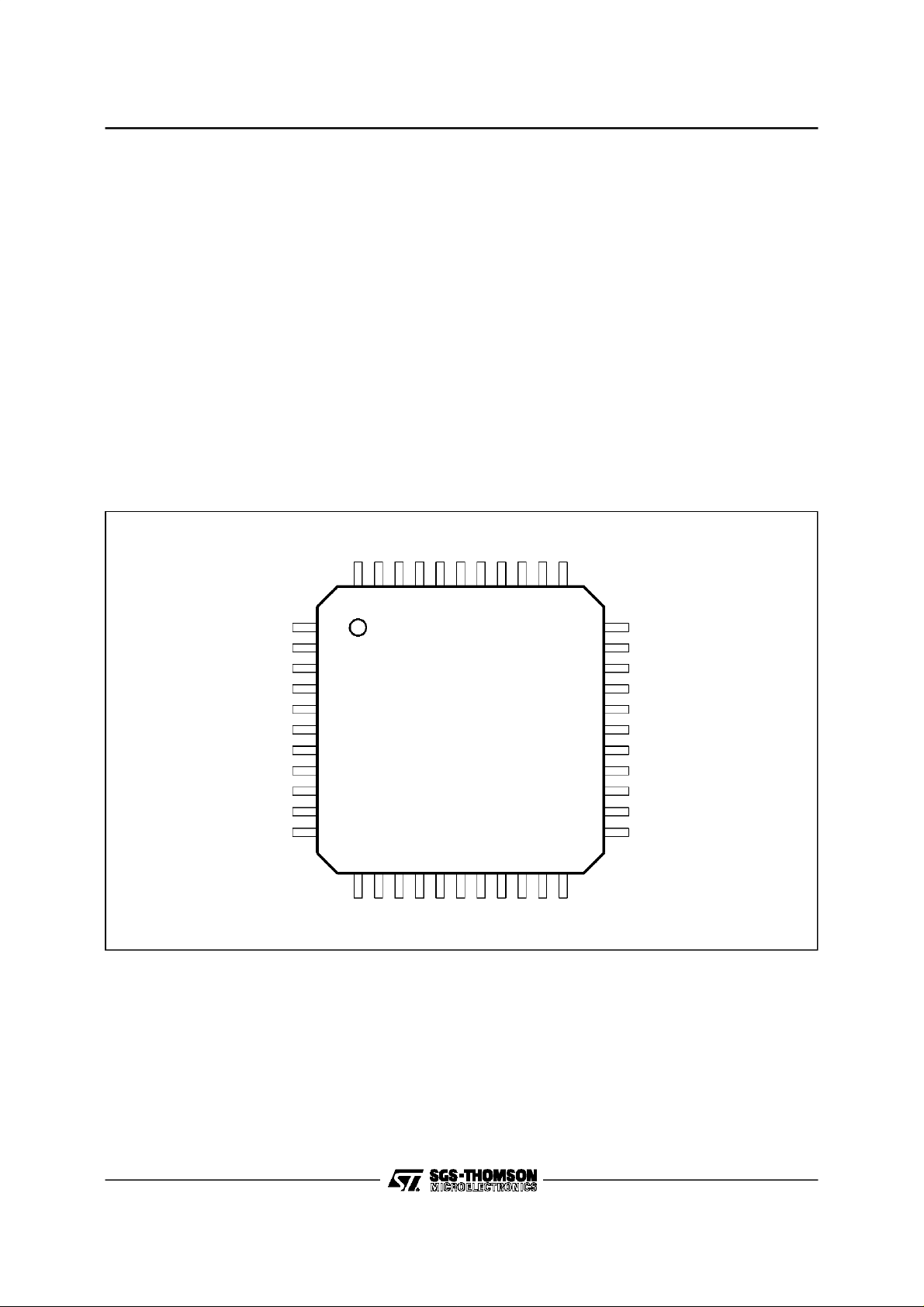
PIN CONNECTIONS
DTMF2
GNDP
RCO
V
V
VL
V
REFL
LSIN
LSSOF
DTMF1
V
RMC
OSC
RI/VI
RESET
LSOUT
4443424140393837363534
1
LS
2
MC
3
4
5
6
7
8
9
10
11
1213141516171819202122
The MCU throughthe serial bus interface.
The concept using TAFE and Microcontroller is
calledBICHIPapproach.
BENEFITS
The benefits of this concept are :
- Saving of externalcomponents.
- Easy upgrade of the features (memories, LCD
driver,Answeringmachine, FAX, Cordless ...).
- Replacement of configuration switches
(PABX/Public, Tone/Pulse) and potentiometers
for loudspeakerand ringer control, by EEPROM
settings.
- Reliability and cost improvements.
RSU
SWP
VZP
GREC
EAR-
EAR+
ISL
33
32
31
30
29
28
27
26
25
24
23
ILL
AGND
SLP
VS
I
REF
SOFTL
TSOFT
V
CC
V
REF
MIC2
MIC1
2/24
PON
CLK
DATA
SNSL
SNLL
ASQ
ASC
RECIN
REOUT
GTR
HFIN
7092-01.EPS
Page 3
PIN DESCRIPTION
Pin Number Name Description
1V
2V
LS
MC
3 VL Transmit Output
4V
REFL
5 LSIN Loudspeaker Amplifier Input
6 LSSOF Loudspeaker Softclipping Time Constant
7 DTMF1 DTMF Filter 1
8V
RMC
9 OSC Oscillator Input
10 RI/VI Ring Indicator / Line Current Variation Indicator
11 RESET Microcontroller Reset Output
12 PON Line Current Indicator Output
13 CLK Serial Bus Clock Input
14 DATA Serial Bus Data Input
15 SNSL Short Line Sidetone Network Input
16 SNLL Long Line Sidetone Network Input
17 ASQ Antiacoustic & Squelch Time Constant
18 ASC DC Offset Cancellation of Squelch Amplifier
19 RECIN Receive Input
20 REOUT Receive Outputfor Handsfree Interface & Loudspeaker Input
21 GTR Transmit Gain Adjustment
22 HFIN Handsfree Microphone Input Referenced to V
23 MIC1 Microphone Input 1 Referenced to V
24 MIC2 Microphone Input 2 Referenced to V
25 V
26 V
REF
CC
27 TSOFT Transmit Softclipping Time Constant
28 SOFTL Softclipping Adjustment
29 I
REF
30 VS Active Self Inductor & DC Characteristic Adjustment
31 SLP DC Mask Slope Adjustment
32 AGND Analog Ground & Negative Line Voltage
33 ILL Long Line Speech Control Adjustment (GMAX)
34 ISL Short Line Speech Control Adjustment (GMAX-6dB)
35 EAR+ Earphone Output
36 EAR- Earphone Output
37 GREC Receive GainAdjustment
38 VZP Switch Mode Power Supply Internal Zener
39 SWP Switch Mode Power Supply Output Switch
40 RSU Ring Start-up Level
41 RCO Ring Power Output Control
42 DTMF2 DTMF Filter 2
43 GND Power Ground & Negative Line Voltage
44 LSOUT Loudspeaker Output
Loudspeaker Power Supply
Unregulated Input of Microcontroller Power Supply
Loudspeaker Reference Voltage (VLS/2)
Stabilized Microcontroller Power Supply
REF
REF
Speech Reference Voltage (VCC/2)
Speech Power Supply
Resistor to Set Reference Current
TEA7092
REF
7092-01.TBL
3/24
Page 4

TEA7092
BLOCK DIAGRAM
REFL
GND 0V
V
LSSOF
LS
V
LS
V
CC
V
TEA7092
13 4615 161926 30
VLS/2
CTRL
LOGIC
HOLD
ILdc 82.ILac I(vls)
STATUS
I LINE SENSING
ILdc
&OUT TX
LOUDSPEAKER
CURRENT SUPPLY
ILac+dc
DC BIAS
AGC
Gmax-Gtl
A
100
INPUTS
LSOUT
SAT
DETECT
DIGITAL
MUX
44
VOLUME
CONTROL
7 steps 4dB
AGC
+RING
LOUDSPEAKER
GND 0V
POWER
LOUDHEARING
Gtl -10 -15 -20 -25dB
VLS
VZP
38
POWER
RCO
41
RING SIGNAL
OUTPUT POWER
(3mA)
CURRENT
EXTRACTOR
GND 0V
RSU
40
POWER
SWITCH MODE
RING
OPTIMISATION
RING
INDICATOR
DC
SERIAL
REGULATOR
ILdc ILac+dc
SWP
39
SUPPLY
CONTROL
ILdc
PON &
GND 0V
RESET
CONTROL
OSCILLATOR
LOGIC CONTROL
RING
MELODY
GENERATOR
LOGIC
SERIAL INTERFACE
MICROCONTROLLER
MUTE
LS
V
GND 0V
3.58MHz
9
14 13 10111282
RMC
V
PON RESET DATA CLK RI/VI OSC
RMC
V
MC
V
4/24
Zasl
LINE
Zall
VS RECINVL SNSL SNLL
CC
V
ILdc
VCC/2
25
REFIREF
V
ILdc
DC
CARACTERISTIC
I&V
REFERENCES
29
31
SLP
LSIN
5
MIXER
SIDETONE
AGC
20
37
GREC
REOUT
AGC CONTROL
MUTE
VERSUS
LINECURRENT
VREF
36
EAR-
RX & TX
-1
EARPHONE
AMPLIFIER
35
EAR+
EARPHO NE
17
ASQ
ASC
dc cut
VL
18
SOFTL
Tx. AMP
MUTE & DTMF
G=200
SQUELCH
ANTI-HOWLING
SOFTCLIPPING
272824
MIC2
TSOFT
1/RGT
AGC
A=10
23
MIC1
MICRO
HAND-FREE
22
HFIN
C21
21
GTR
333432
ILL
RGT
BEEP
VREF
DTMF
I-DACLF I-DACHF
ISL
AGND
SINE CODE
43
GND
742
DTMF1 DTMF2
GND 0V
7092-02.EPS
Page 5
TEA7092
ABSOLUTEMAXIMUM RATINGS
Symbol Parameter Value Unit
V
RECIN
V
L
I
L
V
RSU
V
SWP
V
VLS
V
VCC
V
VM
V
VRMC
V
PON
V
CLOCK
V
DATA
V
RI/VI
T
oper
T
T
stg
Note: Typical Thermal resistance TQFP44 Copper lead frame70° K/W @ 1W.
Supply Voltage 13 V
Line Voltage 13 V
Line Current 0.15 A
Ring InputVoltage 22 V
Output SwitchVoltage 7 V
Loudspeaker Part Supply 5.5 V
Speech PartSupply Voltage 10 V
Unregulated Microprocessor Supply Voltage 5.5 V
Regulated Microprocessor Supply Voltage 5.5 V
Power-On Out Voltage V
Clock In Voltage V
Data In Voltage V
RI/VI Out Voltage V
+0.3V, GND-0.3V V
RMC
+0.3V, GND-0.3V V
RMC
+0.3V, GND-0.3V V
RMC
+0.3V, GND-0.3V V
RMC
Operating Temperature -20, +70 °C
Junction Temperature -20, +150 °C
j
Storage Temperature -55, +150 °C
7092-02.TBL
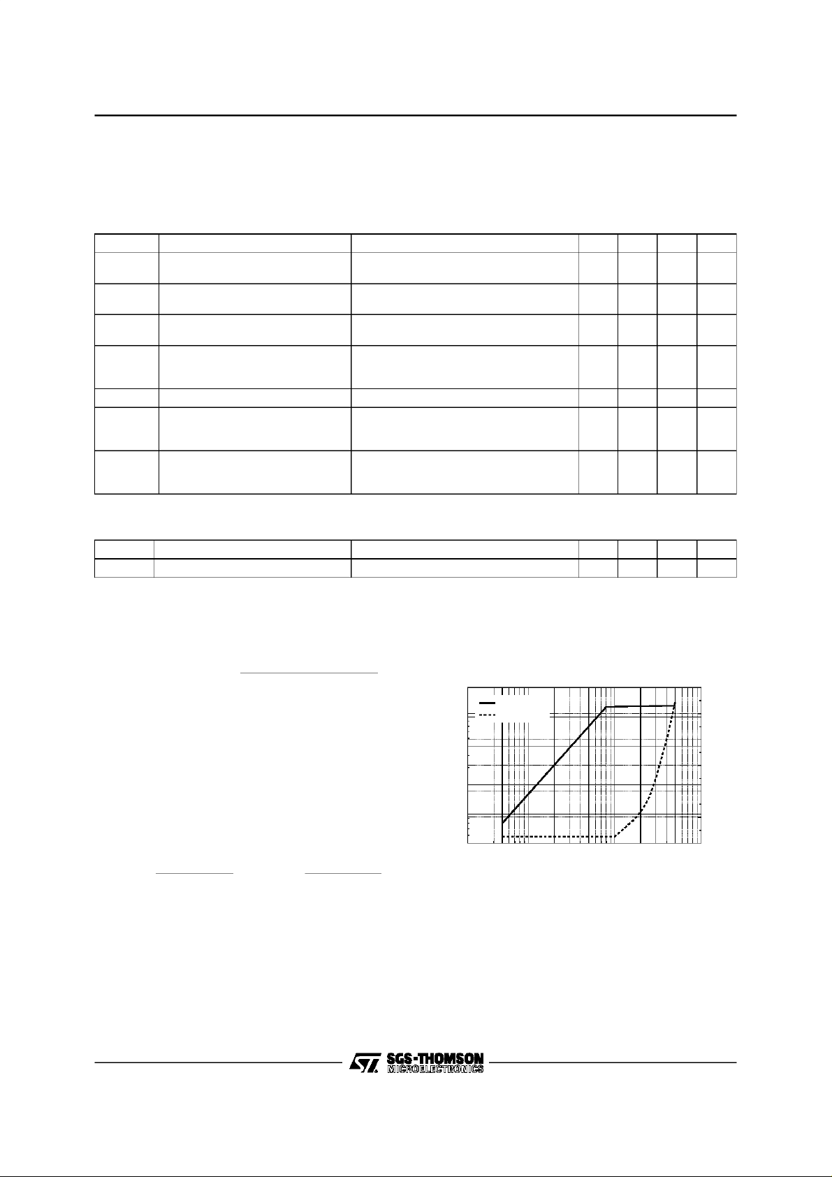
Figure 1 : SafeArea
140
120
100
80
(mA)
L
60
I
40
20
0
02468101214
VL(V)
7092-03.EPS
5/24
Page 6
TEA7092
DC CHARACTERISTICS (T
BetweenI
) =RS x (40E-6+0.5E-3xIL) +RSLP/55 x (IL- 5.6E-3).
V
L(IL
=8mA and IL= 20mAthe DC slopeis fixed by RS and RSLP :
L
For linecurrenthigherthan20mAthe slopeis fixed by RSLP: V
=25°C,see Test 1)
amb
)=VL(20E-3)+ RSLP/55x(IL- 20E-3).
L(IL
Symbol Parameter Test Conditions Min. Typ. Max. Unit
4.1
4.7
V
V
I
LSQ
Line Voltagein Speech Mode IL= 20mA
L1
Line Voltageafter Having Sent
L2
0010101 Mask Code
Loudspeaker Amplifier Quiescent
Bias Current
Unstabilized Supply :
I(VMC)1
I(V
MC
V
RMC
(V
L-VLS
(V
L-VLS
I
LS1
- Startup Current
)2
- UnregulatedInput Current
Stabilized Microprocessor Supply IL= 20mA, I(V
DropVoltage V
I
LS
)1
)2
Loudspeaker CurrentSupply VLS=2V
RETURN LOSS (T
=25°C,see Test 2
amb
= 90mA
I
L
6.6
IL= 20mA 1.6 2.5 V
VLS= 4.5V 1.1 2.2 mA
= 20 mA, VLSno connect, VMC= 2.4V
I
L
V
RMC
V
RMC
LAC
IL= 20mA
I
L
I
L
I
L
= 2.4V
= 3.75V
=0V
RMS
= 90mA
= 20mA
= 90mA
) = -1.8or 0mA 3.2 3.5 3.75 V
RMC
10215
117013
5.25
7.5
8.4VV
2.7 3.6mAmA
1.1
1.3
1.8
2.3VV
77
Symbol Parameter Test Conditions Min. Typ. Max. Unit
RLoss Return Loss I
= 20mA, f = 1000Hz 20 23 dB
L
mA
mA
7092-03.TBL
7092-04.TBL
TRANSMIT CHARACTERISTICS
The maximum gain Gtl is adjustable between 44
and 56dB versusRGT value
Gtl = 20 x log
= internal impedance at Pin VL#8kΩ.
Z
IN
( RZ// RL + R3 ) // Z
820 x
RGT// 50kΩ
IN
The AGC variation is programmable through two
external resistorsconnected on Pins ILL and ISL.
ILL is the line current at which the gain is at the
maximumvalue and ISLis the line currentat which
the gain is at the maximum value minus 6dB. For
line current lower than ILL or higher than ISL, the
transmitand receivegains have a constantvalue.
The following formulas give RLL and RSL values
versus ILL and ISL.
RSL =
310
ISL− 5.6mA
and RLL =
310
ILL − 5.6mA
Tx Softclipping(see Figure 2)
Figure2 : TxSoftclipping and Distortion
at I
=20mA
L
2
V
LINE
Distortion
1
)
0.5
RMS
(V
L
V
0.2
0.1
0.05
0.2 0.5 1 2 5 10 20 100
(mV
V
MIC1-MIC2
RMS
)
50
12
10
8
6
4
2
0
) (%)
L
D(V
7092-04.EPS
6/24
Page 7
TEA7092
TRANSMIT CHARACTERISTICS (continued)
Maximum Level on Line in Tx (see Figure 3)
The minimumoperating voltage of the TEA7092is 2.5V. At low line currentvalue, when the voltageover
the TEA7092is low, thesoftclippingfunctionautomaticallylimitsthe AC dynamicto avoidto reach the 2.5V
limit on the TEA7092.
When the DCvoltageover the TEA7092is high enough, the AC dynamicis limitedat a valuefixed by the
external resistor RSOFTconnectedon PinSOFTL.
The Valueof RSOFT is performed by : RSOFT= (RS x 50E
-6
- 0.8- VacPeak)/ 40E
-6
Tx Characteristics (T
=25°C,f = 1kHz,seeTest 3)
amb
Symbol Parameter Test Conditions Min. Typ. Max. Unit
Gtl
Transmit gain in Handset Mode V
Gtsm
Transmit gain in Handsfree Mode V
Ghl
Ghfm
Gt-6dB Transmit Gain
(-6dB intransmit path)
Zmic
Zhf
Ntx
Nhf
Handset Mic Input Impedance
Handsfree MicInput Impedance
Transmit Noise in Handset Mode
Transmit Noise in Handsfree Mode
Mmic Microphone Mute V
V
Lpeak
Transmit SoftclippingLevel See Figure 2, Vem= -42dBV, IL= 20mA 1.0 1.4 1.8 Vpeak
Transmit Distortion I
Dtx1
Dtx2
Squelch on Transmit Channel (T
amb
=25°C,f = 1kHz, IL=20mA, seeTest3)
= -48dBV
em
= 20mA
I
L
= 90mA
I
L
= -28dBV, Code 0110010
hfin
= 20mA
I
L
= 90mA
I
L
= -48dBV, IL= 20mA
V
em
Code 0110110
Between Pins MIC1, MIC2
Between HFIN and V
= 20mA, Code 0110010
I
L
2kΩ between MIC1 & MIC2
2kΩ between HFIN & V
= -48dBV, IL= 20mA 60 dB
em
= 20mA, see Figure 2
L
= -48dBV
V
em
= -36dBV
V
em
REF
REF
443745394641dB
241725192621dB
567dB
301540205025kΩ
-75
-75
dB
dB
kΩ
dBmp
dBmp
1
%
5
%
The principle of the squelch is to reduce the transmitgain as soon as the amplitude of the signal on the
microphoneis lower than a fixed thresholdvoltage, VT2.
Symbol Parameter Test Conditions Min. Typ. Max. Unit
Gtlmax
Gtlmax-Gsq
Transmit Gain V
em1
V
em2
= -75dBV
= -65dBV
36
45
Gsq Gain Variation See Figure 4 / 9 dB
dB
dB
Figure 3 : Line PeakVoltage versus DC Line
Current
10
V
AC Pe a k
(V)
L
V
8
6
4
2
2.5V Min. Line Pea k Voltage
V
20 40 60 80 1000
DC Mask
AC Peak
IL(mA)
Figure4 : TransmitGain versus Microphone
AC Input Signal
Trans mit
Gain (dB)
Gtlmax
Gtlmax - Gsq
7092-05.EPS
V
em1
Dgt
V
T1
V
T2
Microphone AC Voltage
V
em2
Gst
V
(dBV)
7/24
em
7092-06.EPS
Page 8
TEA7092
RECEIVECHARACTERISTICS (T
=25°C,f = 1kHz)
amb
Symbol Parameter Test Conditions Min. Typ. Max. Unit
Eff Sidetone Efficiency Test 3, V
Gain
Test 2
Grl
Grs
Grs+6
+6dB Code [0010110]
Distortion Test 2, I
Drx1
Drx2
Nrx Noise Test 2, I
Mrx Mute Test 2, I
Z
Z
OUT
Input Impedance Between Pins SNSL & SNLL 120 150 kΩ
IN
Output Impedance 5 Ω
I
I
I
V
V
= -48dBV, IL= 20mA 26 dB
em
= 20mA
L
= 90mA
L
= 90mA
L
= 20mA
L
= -3dBV
ear
= 0dBV
ear
= 20mA -76 dBmp
L
= 20mA, VL= -9dBV 60 dB
L
5
-1.2
5
6
0.8
6
7
2.8
7
3
5
dB
dB
dB
%
%
The sidetoneof theTEA7092usestwo networks,these twonetworksareinternallymixedbetweenlongline
lengthand short line length.
The following equation givesthe sidetone impedanceversus linecurrent: ZAL = K x ZALL+ (1 - K)x ZASL
K=1forI
=ILL ;K= 0 forIL=ISL,and K varieslinear l ybetween1 and0 when ILvari esbetweenILL and ISL.
L
It is possibleto use only the standardone sidetone conceptby short-circuitedPins SNSL ans SNLL.
Gain Control Inhibition FacilityFor PABXApplication
(T
=25°C,IL=20mA, f = 1kHz / NoAGC mode selected 0010100)
amb
Symbol Parameter Test Conditions Min. Typ. Max. Unit
Gtp Transmit Gain Test 2 Gtl - 3 Gtl- 2 Gtl -1 dB
Grp Receive Gain Test 3 Grl- 3 Grl - 1.4 Grl - 0.5 dB
LOUDSPEAKERAMPLIFIER PART
LoudspeakerAmplifier Channel (T
=25°C,f = 1kHz, RLS=50Ω, Vem=0)
amb
The Loudspeakeramplifier channelhas a maximumgain of 35dBbetween Pin LSIN and Pin LSOUT. This
gain is programmablethrough the serialbus interface, 7 stepsof 4dB each.
To avoid distortion, the output level on the loudspeaker is controlled by a softclippingfunction, the time
constant of thisfeature is connectedto LSSOF pin.
Symbol Parameter Test Conditions Min. Typ. Max. Unit
GAIN VHP/Vac Test 4 IL = 20mA
GLS0 GMAX Code: (0 1 0 0 1 1 1) 33.5 35 36.5 dB
GLS1 GMAX-4dB Code: (01 0 0 1 1 0) 29.5 31 32.5 dB
GLS2 GMAX-8dB Code: (01 0 0 1 0 1) 25.5 27 28.5 dB
GLS3 GMAX-12dB Code: (01 0 0 1 0 0) 21.5 23 24.5 dB
GLS4 GMAX-16dB Code: (01 0 0 0 1 1) 17.5 19 20.5 dB
GLS5 GMAX-20db Code: (0 1 0 0 0 1 0) 13.5 15 16.5 dB
GLS6 GMAX-24dB Code: (01 0 0 0 0 1) 9.5 11 12.5 dB
GLS7 GMAX-28dB Code: (01 0 0 0 0 0) 5.5 7 8.5 dB
Mls Mute Loudspeaker Test 4 -30 dB
lsin Input Impedance 30 40 50 kΩ
PLS1
PLS2
Output Power Test 4, Gain= GLS0, V
IL= 20mA, D ≤ 2%
= 90mA, D ≤ 2%
I
L
= 0.15V
IN
RMS
13
40
18
55
mW
mW
8/24
Page 9

TEA7092
LOUDSPEAKERAMPLIFIERPART(continued)
AntiacousticFeedback (T
The antiacoustic feedback system is coupled to the microphone squelch. As soon as the level on the handset
microphoneis higherthanVT2,thetrans m it gainincreasesand theloudspeakergaindecre as es.Sothetrans mi t
andloudspeak ergai nsareneversim ultane ouslyat maximum gain,whichreduceslarseneffec t.
Symbol Parameter Test Conditions Min. Typ. Max. Unit
Dgls(0)
Antiacoustic Feedback Efficiency Code 0111100
Dgls(1)
Dgls(2)
Dgls(3)
Figure5 : LoudspeakerGain GLSversus Voltage on Microphone
=25°C, IL=20mA, see Test4)
amb
Code 0111101
Code 0111110
Code 0111111
-12
-17
-21.5
-26.5
-9.5
-14.5
-18.5
-22.5
-7
-12
-15.5
-18.5
dB
dB
dB
dB
Gtr (dB)
Gma x
Gma x - 9dB
GLS
GLS - xdB
Low Microphone
Level
3dB
VT1V
Normal Speech
9dB
T2
GLS is Programmable through the Volum e Control S ta g e
x is Programmable through the S e rialBus
(10, 15, 20, 25dB) (defaultvalue is 15dB)
High Microphone Signal
Softclipping Mode
V
SOFT
V
MIC
V
MIC
RING MODE
LoudspeakerPower Supply in Ring Mode (T
=25°C,RLS=50Ω, seeTest 5)
amb
In ring mode, it is neccessaryto convert thehigh voltage / lowcurrent power input to a low voltage / high
currentpower,outputto be able to drivea 50Ω loudspeaker,the externalswitchmode powersupply driven
by the TEA7092realizes thisfeature.
The switch mode powersupply, through externalcomponent values,fixes the impedance and the start up
thresholdlevel.
The volumecontrolinring modeisthe samethan the one usedin loudspeakingmodefor thehigheststeps,
8 stepsof 4dB, and5 morestepsof 4dBeach have beenadded,by using the code 0111011,for the lowest
one, by this way the maximum depth in ring modefor the volume control is 48dB.
Symbol Parameter Test Conditions Min. Typ. Max. Unit
40
I
LEAK1
I
LEAK2
I
RON1
I
VRSU
V
V
RMC1
V
V
RES1
V
V
RMC2
V
V
RES2
V
LS1
RI1
LS2
RI2
OUT
Leackage Current V
= 16V, I(VZP) = 0
RING
V
RING=VRSU
= 22V, I(VZP) = 20µA
130
Input Current
Start up Current 60 150 µA
LS Supply 2.8 3.05 3.5 V
Stabilized Microprocessor Supply 2.75 3 V
V
= 22V
RING
I(VZP) = 140µA, I(VLS) = 40mA
No codesent, no signal on the
loudspeaker output
Ring Indicator Output 2.7 2.95 V
Reset Output 2.7 2.95 V
LS Supply
Stabilized Microprocessor Supply 3 3.4 3.75 V
Ring Indicator Output 2.9 3.3 V
Reset Output 2.9 3.3 V
LS Output Level 5 5.4 V
= 22V, I(VZP) =250µA,
V
RING
Gain = Gain Max.,
Codes sent :
- Grouplistening
- FI = 26321Hz & n = 60
- Ring start
5 5.4 V
150
400µAµA
10 12 mA
PP
7092-07.EPS
Ring Frequency
The frequenciesof the ringare givenby :Fring =
Fi
.
n
Fi cantake one of thefollowing values: 19455Hz,21308Hz, 23551Hzor 26321Hz,and n varies between
1 and 63. Fi and n correspondto 2 codes sent on the serialbus.
9/24
Page 10

TEA7092
DTMF GENERATOR (T
Symbol Parameter Test Conditions Min. Typ. Max. Unit
Amf Tone Frequency Accuracy f = 3.58MHz, I
Llf Low Frequency GroupLine Level I
LhF Hifh Frequency Group Line Level I
Pmf Preemphasis HF/LF I
t
t
Velf
Vehf
Vllf
Vlhf
Rise Time IL= 20mA & 90mA 5 ms
R
Decay Time IL= 20mA & 90mA 5 ms
diff
Confidence Tone Level :
- Earphone Level (Low Frequency)
- Earphone Level (High Frequency)
- Loudspeaker Level (Low Frequency)
- Loudspeaker Level (High Frequency)
=25°C,see Test 3)
amb
= 90mA -0.4 0.4 %
L
= 20mA & 90mA -9.5 -8 -6.5 dBm
L
= 20mA & 90mA -7.5 -6 -4.5 dBm
L
= 20mA & 90mA 1 2 3 dB
L
= 20mA & 90mA
I
L
Code Level (0100111)
-35
-33
-10
-8
-32
-30
-7
-5
-29
-27
-4
-2
dBm
dBm
dBm
dBm
Unwantedfrequenciescomply with CEPT46-03.
SINE WAVE GENERATOR (T
=25°C,IL=20 & 90mA, see Test 3)
amb
The sine wave generator uses the same path than theDTMF generator.Sinus wave frequenciesare the
half of the DTMF frequencies.
Symbol Parameter Test Conditions Min. Typ. Max. Unit
Sfl Line Level Low Frequency Group 348 / 385 / 426 / 470Hz -18 -14 -10 dBm
Sfh LineLevel High Frequency Group 604 / 668 / 738 / 816 Hz -16 -12 -8 dBm
ERROR BEEP GENERATOR
Fi
=
The frequenciesof the error beep generatorare given by: F
EB
.
n
Fi can takeone thefollowing values : 19455Hz, 21308Hz, 23551Hz or 26321Hz,and nvariesbetween 1
and 63.
Error beepgeneratorcode generates square wavesignal in the earphone.
Error beep generator code followingby group listening code generatesquare wave signalin theearphone
and inthe loudspeaker.
10/24
Page 11

MICROCONTROLLER INTERFACE
MicrocontrollerPower Supply
The microcontroller power supply consists in a
serial regulator which generatesa 3.5V regulated
supply on V
applied on V
The V
Pin can be supplied either by the line, a
MC
battery or any DC generator.The use of V
allows to regulate the output V
Pin, from an unregulated voltage
RMC
or VLSPin.
MC
voltage for an
RMC
MC
input
LCD display. With no load,the quiescentcurrent,
is 60µA. Foran outputcurrent of 1.8mA,the typical
drop voltage between V
MC
and V
RMC
Pins is
150mV.
MicrocontrollerControl Signals
RESET : This output is setting to “1”when V
RMC
reachesthe 2.6V threshold level.This outputgoes
back to ”0” :
-IfV
goesbelow 2.5Vor
RMC
- If the Reset code (0010111) is sent on theserial
bus interface and if PONoutput is at level ”0”.
Whenthe Reset code hasbeen previouslysent,
Pin RESETgoes back toan high level,if V
RMC
is
Figure 6 : MicroprocessorPower Supply Block Diagram
TEA7092
higher thantherise threshold, onlyon ariseedge
of PON signal. If this PON rise edge does not
appear,the RESETPinremains at low logic level
even if V
WhenPONoutput isat level”1”, the Resetcode is
inhibited.
PON : This output goes high when V
the 2.6Vthreshold level and the line currentvalue
is upper than 12mA. As soon as theReset output
is atlevel ”1”, the4mAline currentthresholddetector can be sent through the serial bus interface
(0111001) to check if the line current value is between 4 and 12mA.
RI/VI :
- In Ringmode : This output goes to level ”1” if :
• Pin RSU > 19V
• Pin V
- In Off-Hookmode : This output manages the line
current variation indicator for transfer function
and thisinformationis usedbythemicrocontroller
to managethe transfer from one telephonesetto
an other one connected in parallel on the same
line.
goes upper 2.6V.
RMC
> 2.6V
RMC
RMC
reaches
3
V
L
3mA I
>1M
Ω
Switch Closed if:
V
V
> 2.5V or
RMC
>20V
RSU
LS
V
LS
1
+
Ring Information
C1
11
12
8
RESET
PON
V
RMC
+
> 12m A(01110 00) or
I
L
> 4mA(0111001)
I
L
2.5V
C8
135k
Ω
2
V
+
MC
1.2V
90k
Ω
C2
7092-08.EPS
11/24
Page 12

TEA7092
MICROCONTROLLER INTERFACE (continued)
Reset and Power On
Figure 7 : TelephoneSet Poweredfrom the Line,IL>I
Without Using the RESET Code Through the Se rial Bus Interface
AABCD DE
IL
I
REF1
VMC
5
2.7
REF1
, without Batteries
t
V
RMC
3.5
2.6
PON
RESE T
Us ing the RES ET Code Through the Serial Bus Interfa ce
IL
AB CD DEDFA
I
REF1
VMC
5
2.7
V
RMC
3.5
2.6
t
t
t
t
t
t
PON
RESE T
A: ON-HOOK
B : START UP + S PEEC H
C:PULSEDIALING
D : SP EECH or DTMF
E : LINE BREAKEXCHANGE DURATION
F : LINE BREAKEXCHANGE DURATION> td
td : DELAYFIXED BY THE MICROCONTROLLER
12/24
tdtd
Re set code (0010111) sent by
the microcontroller.
t
t
t
7092-09.EPS
Page 13

TEA7092
MICROCONTROLLER INTERFACE (continued)
MicrocontrollerStabilizedSupply (T
Symbol Parameter Test Conditions Min. Typ. Max. Unit
V
RMC1
V
RMC2
Ivmcq1
Ivmcq2
Ivmcq3
Output Voltage I(V
Quiescent Current
I(V
MC
) - I(V
RMC
)
=25°C, IL= 0mA)
amb
RMC
I(V
RMC
V
MC=VRMC
Oscillator ON, I(V
Code 0111010 I(V
) = -1.8mA, VMC= 4V, VLS=0V
) = 0, VMC= 0V, VLS=4V
+ 0.3V
)=0
RMC
) = -1.8mA
RMC
)=0
I(V
RMC
3.2
3.2
3.5
3.5
250
95
50
3.75
3.75VV
400
200
120
µA
µA
µA
RESET (T
=25°C,IL=0mA)
amb
Symbol Parameter TestConditions Min. Typ. Max. Unit
= 1mA, VMC=4V
I
V
RESL
V
RESH
PON (T
Low Threshold
High Threshold
=25°C)
amb
RESET
V
V
RMC
RMC
= 0.66 x V
= 0.8 x V
RMC1
RMC1
V
RMC
- 0.4
0.4 V
Symbol Parameter TestConditions Min. Typ. Max. Unit
= -1mA
I
V
V
PONH1
V
PONH2
PONL
Low Threshold
High Threshold
High Threshold
RI/VI ,Hold Function (T
amb
=25°C)
PON
Code (0111000), I
Code (0111000), I
Code (0111001), I
= 8mA
L
= 20mA
L
= 8mA
L
V
0.4 V
- 0.4
RMC
- 0.4
V
RMC
Symbol Parameter TestConditions Min. Typ. Max. Unit
V
V
RIVIL
RIVIH
Low Threshold
High Threshold
IL= 90mA, Code (0011010)
= 70mA V
I
L
RMC
- 0.4
0.4 V
V
V
V
V
13/24
Page 14

TEA7092
MICROCONTROLLER INTERFACE (continued)
Serial Bus Interface (data and clock)
The serial bus uses 7 bits, a standard 8 bit word
can be sent, the TEA7092 take care only of the
seven first bits.
The differentcodes are :
- The ring start up code
- The ring frequencycontrol code
- The mode codes :
• Handsetmode
• Grouplistening mode
• Handsfreemode
- The operatingcodes (these codes are used under each codemode) :
• Speech
• Dialing
• Microphonemute
• Earphone/Microphonemute
• Error beep
• Sine wavehigh frequency
• Sine wavelow frequency
- The data codes (DTMF, sinus wave, ring frequency,error beep frequency codes) :
Thesedata codes arestoredinside theTEA7092
and are used as soon as an operating code is
sent,dialing,errorbeep,sinewaveorringmelody
controlor ring start upcode.
- The configuration codes (those codes are ”flipflop” codes) :
• AGC/noAGC
• No mask / mask
Figure 8 : 7 Bit Codes Dataand Clock Input Timing
• Normal gain/normal gain +6dB, on receive
channel
• Twosidetone network/one sidetone network
• Squelch/Nosquelch
• Line current variation initialization (No trans-
fer/Transfer)
• Minus 21dB in Ring Mode
• Minus 6dB in SendingMode
• OscillatorStand-by
For instance: The first time that the +6dB codeis
sent,thereceivegainincreasesof+6dB.Ifitissent
again,the receive gain goesbackto normalvalue.
- Theloudspeakerlevel control codes
- Theresetcodeto inializetheTEA7092andto set
the resetoutput to ”0” lowlogic level
- TheInit code to initializethe TEA7092, software
initialization to set the TEA7092 in the start up
condition.
- Thestart up condition of the TEA7092is :
• Handsetmode.
• Speech.
• No mask.
• AGC in transmitand receivechannels.
• Normalgain on receivechannel.
• Squelchon transmit channel.
• Twosidetone networks.
• No transfer.
• OscillatorON.
• PON line threshold current: 12mA.
• Anti-acousticfeed-backattenuation: 15dB.
Ik Data
14/24
Datas will change during Clk = 1
t1 t2t3 t4 t5
ata
Synchro
a0 a1 a2 a3 a4 a5 a6
t1 = t2 = t4 = t5 = 1µs
t3 = 2µs
7092-10.EPS
Page 15

MICROCONTROLLER INTERFACE (continued)
Note : In the tablesin thefollowingpages, the default codes are in Bold.
The Mode Codes
Codes
a6 a5 a4 a3 a2 a1 a0
0
0
0
1
1
1
1
1
1
0
0
0
0
0
0
0
0
1
0
Handset Mode
1
Group Listening Mode
0
Handsfree Mode
The OperatingCodes Related to Mode Codes
Codes
a6 a5 a4 a3 a2 a1 a0
0
0
0
0
0
0
0
0
0
0
0
0
0
0
1
1
1
1
1
1
1
0
0
0
0
1
1
1
0
0
0
0
1
1
1
0
0
1
1
0
0
1
0
Speech
1
Dialing
0
Mute Tx & Rx
1
Mute Tx
0
Error Beep
1
Sine Wave High Frequencies
0
Sine Wave Low Frequencies
The ConfigurationCodes (toggle codes)
Codes
a6 a5 a4 a3 a2 a1 a0
0
0
0
0
0
0
0
0
0
0
0
0
0
0
1
1
1
1
1
1
1
0
0
0
1
1
1
1
1
1
1
0
0
0
0
0
0
1
0
0
1
1
0
AGC / no AGC
1
No Mask / Mask
0
Normal Receive Gain / +6dB
0
Two Sidetones / Fixed Up (3/4 x ZALL +1/4 x ZASL)
1
Squelch / No Squelch
0
No Transfer / Transfer Request
1
Two Sidetones / One Sidetone (ZASL)
TEA7092
Remarks
Remarks
Remarks
The OtherCodes
Codes
a6 a5 a4 a3 a2 a1 a0
0
0
0
0
0
0
0
0
0
0
0
0
0
0
0
1
1
1
1
1
1
1
1
1
1
1
1
1
0
1
1
1
1
1
1
1
1
1
1
0
0
1
1
1
1
1
1
1
0
1
1
0
0
1
0
0
0
1
1
1
1
1
0
0
0
0
1
0
0
0
0
0
1
1
1
1
1
1
1
Ring Start
1
Reset Control
0
Initialization Code
0
Line Threshold Current 12mA
1
Line Threshold Current 4mA
0
Dgls(1) 10dB
1
Dgls(2) 15dB
0
Dgls(3) 20dB
1
Dgls(4) 25dB
0
Transmit Gain -6dB
1
-21dB Attenuation in Ring Mode
0
Oscillator Stand-by
1
Ring Melody Control
Remarks
15/24
Page 16

TEA7092
MICROCONTROLLER INTERFACE (continued)
HFIN Input Selection
For answeringmachine or cordless connectionit canbe requested to select HFIN input without enabling
the loudspeaker.For this the followingprocedureshould be sent :
- Handsfreecode 0110010.
- Tx& Rx mutes0010010.
- HFINinput select 0110111.
To go backto handsfreemode, send :
- Speechcode 0010000.
To go backto handsetmode, send :
- Speechcode 0010000.
- Handsetcode 0110000.
The LoudspeakerControl Code
Codes
a6 a5 a4 a3 a2 a1 a0
0
0
0
0
0
0
0
0
1
1
1
1
1
1
1
1
0
0
0
0
0
0
0
0
0
0
0
0
0
0
0
0
0
0
0
0
1
1
1
1
0
0
1
1
0
0
1
1
0
Gmax -28dB
1
Gmax -24dB
0
Gmax -20dB
1
Gmax -16dB Loudspeaker
0
Gmax -12dB Level Control
1
Gmax -8dB
0
Gmax -4dB
1
Gmax
Remarks
The DataCodes
These codes are used inthree differentways, dependingof the operatingcode sent after the data codes:
- In DTMFdialing : Data code+Dialingcode
- In Single sine wave : Data code+Sinewave high frequencies(or Sinewave low frequencies)
- In Ring mode, to program the Fi parameter,the Data code is following by the divider code n. Fi and n
codes fix the ring output frequency.
Codes DTMF Dialing Mode
a6 a5 a4 a3 a2 a1 a0 Key DTMF Frequencies
0
0
0
0
0
0
0
0
0
0
0
0
0
0
0
0
0
0
0
0
0
0
0
0
0
0
0
0
0
0
0
0
0
0
0
0
0
0
0
0
0
0
0
0
0
0
0
0
0
0
0
0
0
1
0
1
0
1
0
1
0
1
0
1
0
1
0
1
0
0
1
0
1
1
0
1
0
1
1
1
1
0
0
0
0
0
1
0
1
1
0
1
0
1
1
1
1
“2”
1
“1”
0
“A”
1
“3”
0
“8”
1
“7”
0
“C”
1
“9”
0
“5”
1
“4”
0
“B”
1
“6”
0
“0”
1
“*”
0
“D”
1
“#”
1336Hz + 697Hz
1209Hz + 697Hz
1633Hz + 697Hz
1477Hz + 697Hz
1336Hz + 852Hz
1209Hz + 852Hz
1633Hz + 852Hz
1477Hz + 852Hz
1336Hz + 770Hz
1209Hz + 770Hz
1633Hz + 770Hz
1477Hz + 770Hz
1336Hz + 941Hz
1209Hz + 941Hz
1633Hz + 941Hz
1477Hz + 941Hz
Sine Wave Generator Fi
348 or 604Hz
426 or 738Hz
385 or 668Hz
470 or 816Hz
19455Hz
23551Hz
21308Hz
26321Hz
16/24
Page 17

TEA7092
MICROCONTROLLER INTERFACE (continued)
ProgrammableDivider for Ring Frequencies
Ring Frequencies Ring Frequencies
Fi codes (Hz) / * Notes (Hz) Fi codes (Hz) / * Notes (Hz)
Divider
Codes
1010000
1010001
1010010
1010011
1010100
1010101
1010110
1010111
1011000
1011001
1011010
1011011
1011100
1011101
1011110
1011111
1100000
1100001
1100010
1100011
1100100
1100101
1100110
1100111
If requested,the high frequenciescorresponding to n varied between 1 to 15 or Dividercodes 100XXXX
are accessible.
n
16
17
18
19
20
21
22
23
24
25
26
27
28
29
30
31
32
33
34
35
36
37
38
39
26321
000XX10
1645
1548.3
1462.3
1385.3
1316
1253.4
1196.4
1144.4
1096.7
1052.8
1012.3
974.8
940
907.6
* 877.4
849.1
822.5
797.6
774.1
752
731.1
711.4
692.7
674.9
23551
000XX11
1471.9
1385.3
1308.4
1239.5
1177.5
1121.5
1070.5
1024
981.3
942
905.8
872.3
841.1
812.1
* 785
759.7
* 736
713.7
692.7
672.9
654.2
636.5
* 619.8
603.9
21308
000XX00
1331.7
1253.4
1183.8
1121.5
1065.4
1014.7
968.5
926.4
887.8
852.3
819.5
789.2
761
734.8
710.3
687.3
665.9
645.7
626.7
608.8
591.9
575.9
560.7
546.4
19455
000XX01
1215.9
1144.4
1080.8
1023.9
972.7
926.4
884.3
845.9
810.6
778.2
748.3
720.6
* 694.8
670.9
648.5
627.6
608
589.5
572.2
* 555.9
540.4
525.8
512
498.8
Divider
Codes
1101000
1101001
1101010
1101011
1101100
1101101
1101110
1101111
1110000
1110001
1110010
1110011
1110100
1110101
1110110
1110111
1111000
1111001
1111010
1111011
1111100
1111101
1111110
1111111
n
40
41
42
43
44
45
46
47
48
49
50
51
52
53
54
55
56
57
58
59
60
61
62
63
26321
000XX10
* 658
642
626.7
612.1
598.2
584.9
572.2
560
548.3
537.2
526.4
516.1
506.2
496.6
487.4
478.6
470
461.8
453.8
446.1
* 438.7
431.5
424.5
417.8
23551
000XX11
* 588.8
574.4
560.7
547.7
535.2
* 523.4
512
501.1
490.6
480.6
471
461.8
452.9
444.4
436.1
428.2
420.5
413.2
406
399.2
* 392.5
386.1
379.8
373.8
21308
000XX00
532.7
519.7
507.3
* 495.5
484.3
473.5
* 463.2
453.4
443.9
434.9
426.2
417.8
409.8
402
394.6
387.4
380.5
373.8
* 367.4
361.1
355.1
* 349.3
343.7
338.2
19455
000XX01
486.4
474.5
463.2
452.4
442.2
432.3
422.9
* 413.9
405.3
397
389.1
381.5
374.1
367.1
360.3
353.7
347.4
341.3
335.4
* 329.7
324.2
318.9
313.8
308.8
OperatingModes
TheTEA7092can workin 1 of the 3 modes:
- Handset,
- Grouplistening,
- Handsfree.
In each mode the operatingcodes determine the
operationsheld by thecircuit as soonas this code
is received:
For instance DTMF dialing begins as soon as the
dialingcode is received.
The configurationcodes operate in each modeof
operation: forinstanceif the No AGCcode issent,
the AGCinhibitionwill work in the 3 modes: Handset, Grouplistening and Handsfree.
DTMF Dialing
To dialin DTMF thefollowi ngcodesequenceis sent :
- DTMF: 000XXXX.
- Dialingcode : 0010001.
- Mute or SPEECH code :0010010 or 0010000
(to end DTMF mode).
The duration of the DTMF signal is fixed by the
duration between DIALING code and MUTE or
SPEECHcode
Note : DTMF code automatically mutes the microphone.
Sine Wave Codes
To generate a melody the following sequence of
codes is sent :
- Frequencycode : 000XXXX.
- SINE WAVE code : 0011101or 0011110(low or
high frequency).
- SPE ECHcode:0010000(toendSINEWAVEmode).
The duration of the melody is being set by the
durationbetween SINEWAVE codeand SPEECH
code.
Note : SINE WAVE code automatically mutes the microphone.
PULSEDialing
The pulse dialing function is performed by the
microcontrollerthrough the highvoltage stage.
The voltage over the TEA7092during dialing can
be reducedby sendingthe MASK code 0010101.
Torecover the normalspeechvoltageat the end of
dialingthe maskcode mustbe sentagain.
17/24
Page 18

TEA7092
MICROCONTROLLER INTERFACE (continued)
RING Mode
- Ringfrequencygenerator:
In ring mode, to generatethe ring melody in the
loudspeaker,the followingsequence is sent :
• LOUDSPEAKERLEVEL: 0100XXX.
• Fi DATA : 000XXXX.
• DIVIDERDATA : 1XXXXXX.
• GROUPLISTENINGCODE : 0110001.
• RING START : 0010001.
• SPEECH : 0010000 (To stop the ring mode
when off-hookis detected,PON = 1).
To change the ring frequency only Fi data and
dividerdata are sent again.
- Ringindicatorinput (RI/VI) :
In ring mode theTEA7092generatesa high logic
level on pin RI/VI, as soon as the voltage on pin
RSU is higher than 19V, and the voltage on pin
is higher than 2.6V. When the voltage on
V
RMC
pin V
goes high.
Ring Melody Control
The melodycan be checkedinoff-hookby sending
the followingsequenceof codes :
- LOUDSPEAKERLEVEL : 0100XXX.
- Fi data : 000XXXX.
- DIVIDERdata : 1XXXXXX.
- RINGMELODYCONTROL : 0110011.
To change the melody or the level, only loudspeakerlevel,Fidataand ndivider data haveto be
sent. To stop the ring melody, a speech code
0010000 issent.
Figure 9 : TimeDiagram of Transfer Request
is higher than 2.6V,the RESEToutput
RMC
ErrorBeep
Errorbeepcouldbe usedto signalizewrong operations(memoryempty,re-dialempty,storetoomany
digits in a memory...) or for other procedures,like
melody.To generate the error beep, the following
sequenceof codesis sent :
- Fi data: 000XXXX.
- DIVIDER data : 1XXXXXX.
- ERRORBEEP code : 0011100.
To stop the error beep a speech code 0010000is
sent. The errorbeep is a square wave sent onthe
earphone, if it is requested to send it also in the
loudspeaker,the Group listeningcode shouldalso
be sent.
Line Current VariationDetection
The TEA7092 has a line currentvariation detector.
This feature memorizes the line current value.
Whenthe transferrequestcodeis sent,and if a the
current inside the TEA7092decreases of 15% or
more of theline currentvalue, due for exampleto
a telephoneset off-hookedin parallel on the same
line, the output RI/VI goes HIGH to prevent the
associated microcontroller. Oscillator should be
ON, and it is preferableto mute the transmit and
receive paths to avoid current variation due to ac
signals.
- TRANSFER REQUEST: 0011010.
If the Transfer request code is sent again, the
current memorizationis disabled.
RI/VI
RI/VI
18/24
Transfert Request
t0
Line CurrentMemorizationActivated
Flip-Flop Operating
t0
Line CurrentMemorizationActivated
µPSend theCode (0011010)
µPSend theCode (0011010)
LineCurrentMemorizationCancelled
LineCurrent Variation
(if> 15%of IL)
7092-11.EPS
Page 19

TEA7092
COMPONENT LIST
Reference Part Reference Part Reference Part Reference Part
DC Mask CLL, CSL 33pF Rring 47Ω C26 100µF/16V
RS 82kΩ Resistors RLS 50Ω C27 150nF
RSLP 2.2kΩ R1 220kΩ Rear 300Ω C30 1µF
Return Loss R3 30Ω Capacitors C38 22nF
RZ 620Ω R4 3kΩ C1 68µF/16V C41 470pF
Tx Path R5 3kΩ C2 470µF/6V C44 47µF/6V
RGT 1540Ω R6 220kΩ C3 10µF/63V Others
RSOFT 51kΩ R7 100kΩ C4 47nF D1,D2,D3, D4 1N4004
Rx path R8 1.5MΩ C5 47nF DS1 BYW10-60
RGR1 39kΩ R9 1.5MΩ C6 470nF DS2 BAT43
RGR2 39kΩ R10 10kΩ C7 1nF Z1 BZX55C 47V
DTMF Path R11 12kΩ C8 10µF/6V Z2 BZX55C8.2V
CDT 47nF/1% R17 220kΩ C9 47nF Z3 BZX55C 12V
CDT2 3.3nF R23 2kΩ C15 220nF Q1 BC556B
A.G.C. R25 2kΩ C16 220nF Q2 BC546B
RLL 15kΩ R27 910kΩ C17 470nF Q4 BF393
RSL 4.7kΩ R29 30kΩ C18 1µF M1 BSS 92
Sidetone Networks R39 1.5kΩ C22 47nF L1 1mH
RLL1, RSL1 0 R40 47kΩ C24 47nF
RLL2, RSL2 30kΩ R41 30kΩ C25 47nF Quartz 3.58MHz (Ri < 100Ω)
(R < 4Ω/Imax = 400mA)
7092-05.TBL
19/24
Page 20

TEA7092
Test 1
C
L
I
L
R
L
RZ
RLL2
ZALL
R4
V
L
R3
R5
CLL
RSL2
CSL
ZASL
C16 C1 5
19
3
RS
V
L
RECIN
30
V
S
26
V
CC
22
HFIN
40
RSU
39
SWP
38
VZP
SOFTL
28
AGND
GND
32 33 3435 3637
43 42 41
SNLL
SNSL
REF
REF
SLP
MIC1
V
I
31
29
MIC2
TSOFT
GTR
7 89
23 2425
21
27
To Pin
V
TEA7092
DTMF1
DTMF2
I
I
PON
RESET
Logic
Con tro l
SW2
PON
SW3
1112 13141516
RESET
CC
DATA
CLK
I
RI
V
RI/VI
10
LSOUT
RI/VI
LSSOF
C44
44
R6
6
RLS
C6
5
GREC
EAR+
EAR-
ILL
ISL
RCO
OSC
VMCV
2
LSIN
REOUT
ASC
ASQ
V
REFL
V
RMC
C5
R17
C17
C9
C4
20
C18
18
17
4
1
LS
C26
Test 2
I
L
RZ
C30
C25
R29
RSLP
RSOFT
IL+i
AC
C
L
V
AC
V
R3
R4
L
R5
C16 C1 5
RS
3
V
L
RECIN
30
V
S
26
V
CC
22
HFIN
C22
40
RSU
39
SWP
38
VZP
SOFTL
28
AGND
GND
32 33 3435 3637
43 42 41
SNLL
REF
REF
V
SLP
I
29
31
151619
R23
SNSL
R27
C24
RLL2
CLL
RSL2
CSL
C27
RGT
ZALL
ZASL
CDT1
CDT2
To P in
V
CC
RGR2
RGR1
Logic
Con tr o l
PON
RLL
REAR
7 BitSeria l Cod e
DATA
RESET
RSL
3.58MHz
I
V
VMC
Grl = 20 log a t ILL, Grs = 20 log at ILm
Mea r = 20 log
10 0kHz
CLK
Rlos s =20 log
101112 1 314
RI/VI
V
RMC
MC
+
+
V
ear
V
L
VL(0010 000)
V
Z+600
Z - 600
LSOUT
LSSOF
I
VRMC
(0010 010)
L
44
6
V
LS
+
I
VLS
7092-12.EPS
V
ear
V
L
V
AC
Z=
I
AC
C44
R6
V
HP
RLS
C6
5
LSIN
20
OSC
VMCV
2
REOUT
ASC
ASQ
V
RMC
REFL
V
18
17
4
1
LS
TEA7092
MIC1
MIC2
TSOFT
GTR
DTMF1
23 2425
21
27
DTMF2
7 89
GREC
EAR+
EAR-
ILL
ISL
RCO
R17
C5
C18
C17
C9
C4
C1
20/24
C26
C30
R25
RSOFT
C25
R29
RSLP
R23
R27
C24
C27
RGT
CDT1
CDT2
RGR2
RGR1
REAR
V
EAR
RLL
RSL
3.58MHz
C8C2
7092-13.EPS
Page 21

Test 3
I
L
RZ
C26
C30
TEA7092
V
= 0Vat 20mA, Vem=0V
IL+i
AC
C
L
L
R
V
R3
R4
L
R5
C16 C1 5
R25
RS
3
V
L
RECIN
30
V
S
26
V
CC
22
HFIN
C22
40
RSU
39
SWP
V
hfin
38
VZP
SOFTL
28
REF
AGND
GND
V
43 42 41
32 33 3435 3637
RSOFT
29
R29
151619
SNLL
REF
SLP
MIC1
I
31
23 2425
RSLP
C25
SNSL
R23
MIC2
V
R27
em
C24
CLL
RSL2
CSL
27
RLL2
ZALL
ZASL
To P in
V
Logic
Con tr o l
CC
PON
TEA7092
TSOFT
GTR
DTMF1
21
RGT
DTMF2
7 89
CDT1
CDT2
C27
RGR2
GREC
RGR1
EAR+
RESET
EAR-
REAR
V
7 Bit Se rialC ode
100kHz
DATA
ILL
EAR
RLL
RSL
hfin
Grl = 20 log at ILL
Gts m = 20 log at 9 0 mA
Mmic= 20 log
Eff = 20 log
101112 1314
CLK
RI/VI
ISL
RCO
OSC
3.58MHz
VMCV
2
V
L
V
em
V
L
V
em
VL(001000 0)
V
(001001 1)
L
V
ear
,
V
em
LSOUT
LSSOF
LSIN
REOUT
ASC
ASQ
V
REFL
V
LS
RMC
C8C2
Ghfm = 20 log
C44
44
R6
6
C6
5
C5
20
18
R17
17
4
1
C18
C17
V
L
V
hfin
V
RLS
HP
C9
C4
C1
Test 4
I
L
RZ
C26
RLL2
ZALL
RLL1
V
L
R3
RSL1
CLL
RSL2
CSL
ZASL
C16 C15
3
RS
V
L
30
26
22
40
39
38
28
C30
RECIN
V
S
V
CC
HFIN
RSU
SWP
VZP
SOFTL
REF
AGND
GND
V
32 33 3435 3637
43 42 41
RSOFT
29
R29
C25
151619
SNLL
SNSL
REF
SLP
MIC1
I
31
RSLP
MIC2
TSOFT
GTR
23 2425
R23
R27
21
27
C24
V
RGT
em
C27
7 Bit S e rial Code
Logic
PON
(011001/01000 00)
1112 1314
RESET
DATA
100kHz
CLK
To P in
V
CC
Co ntro l
TEA7092
DTMF1
DTMF2
7 89
CDT1
CDT2
RGR2
GREC
RGR1
EAR+
REAR
EAR-
ILL
ISL
V
EAR
RLL
RSL
Gls = 20 log
Dgls = 20 log
MuteLS = 2 0 log
10
RI/VI
RCO
OSC
3.58MHz
V
HP
V
AC
VHP(Vem= -75d BV)
VHP(Vem= -65d BV)
LSOUT
LSSOF
LSIN
REOUT
ASC
ASQ
V
REFL
V
RMC
VMCV
2
2
V
HP
Pls =
RLS
V
(cod e 0100111)
HP
VHP(cod e 0110000)
C44
44
R6
6
C6
5
C5
20
C18
18
R17
17
C17
4
1
LS
C1
C8C2
7092-14.EPS
V
RLS
HP
V
AC
C9
C4
21/24
7092-15.EPS
Page 22

TEA7092
Test 5
Logic
Con tr ol
3
R
RING
30
V
R1
R11R39
C3
Q1
Q2
Z2
SWP
V
V
RING
+
I
RING
V
RS U
+
I
RS U
)
ZP
I(V
S
26
V
CC
22
HFIN
40
RSU
39
SWP
38
VZP
28
SOFTL
ZP
V
32
AGND
C38
L1
)
LS
DS1
LS
V
I(V
19
V
L
SNLL
SNSL
RECIN
TEA7092
REF
REF
GND
43 42 41
SLP
MIC1
V
I
29
MIC2
TSOFT
23 2425
31
21
27
7 Bit Serial Co de
100kHz
1112 13141516
PON
GTR
DATA
RESET
DTMF1
DTMF2
GREC
79
EAR+
CLK
EAR-
IRI
VRI
10
RI/VI
LSOUT
LSSOF
REOUT
ILL
ISL
RCO
OSC
33 3435 3637
VMCV
28
LSIN
RMC
ASC
ASQ
V
REFL
C44
44
R6
6
C6
5
20
18
17
C4
4
1
V
LS
C1
C8
R41
C41
V
RCO
3.58MHz
RLS
V
HP
7092-16.EPS
22/24
Page 23

TYPICALAPPLICATION
TEA7092
DS2
R8R10
Z3
MICROCONTROLLER
ZALC
RSL2
To Pin
RSL1
CSL
R5
R3
KEYBOARD
ZALL
RLL1
RLL2
CLL
R4
R7 R9
Q4
181920
ASC
R17
C4
C17
17
ASQ
Loud-
speaker
C18
C5
C6
R6
C44
5
6
44
LSIN
LSSOF
LSOUT
RI/VI
101112 13141516
CLK
REOUT
DATA
RESET
PON
C1
1
4
LS
V
REFL
V
RMC
V
MC
V
2
OSC
RCO
ISL
ILL
C2 C8
3.58MHz
RSL
RLL
C41
R41
Earphone
EAREAR+
CC
V
GREC
RGR1
RGR2
CDT2
DTMF2
C16 C15
TEA7092
SNSL
SNLL
RECIN
L
3
V
VCCVS
26
30
HFIN
22
RSU
40
SWP
39
VZP
38
REF
REF
SOFTL
28
DTMF1
GTR
TSOFT
MIC2
MIC1
SLP
I
V
GND
AGND
7 89
21
27
23 2425
31
29
CDT1
RGT
C27
R27
Microphone
RSLP
R29
C25
43 42 41
32 33 3435 3637
RSOFT
Z4
Hookswitch
D1 D2
2.2kΩ
FM1
1
+ LINE+ RING
R38
RS
R40
C38
RZ
C30
D3 D4
Q1
R11R39
Q2
LINE
R1
C26
C3
DS1
L1
Z2
Z1
7092-17.EPS
23/24
Page 24

TEA7092
PACKAGE MECHANICALDATA
44 PINS- PLASTICQUADFLAT PACK(THIN)
D
D1
2333
34
A
A2
A1
22
0.10mm
.004
SeatingPlane
B
C
Dimensions
B
44
1
e
11
TQFP44
E3D3E1
12
E
L1
L
K
Millimeters Inches
Min. Typ. Max. Min. Typ. Max.
A 1.60 0.063
A1 0.05 0.15 0.002 0.006
A2 1.35 1.40 1.45 0.053 0.055 0.057
B 0.30 0.35 0.40 0.012 0.014 0.016
C 0.09 0.20 0.004 0.008
D 12.00 0.472
D1 10.00 0.394
D3 8.00 0.315
e 0.80 0.031
E 12.00 0.472
E1 10.00 0.394
E3 8.00 0.315
K0
o
(Min.), 7o(Max.)
L 0.45 0.60 0.75 0.018 0.024 0.030
L1 1.00 0.039
Information furnished is believed to be accurate and reliable. However, SGS-THOMSON Microelectronics assumes no responsibility
for the consequences of use of such information nor for any infringement of patents or other rights of third parties which may result
from its use. Nolicence isgranted by implication or otherwise under any patent or patent rights of SGS-THOMSON Microelectronics.
Specifications mentioned in this publication are subject to change without notice. This publication supersedes and replaces all
information previously supplied. SGS-THOMSON Microelectronics products are not authorized for use as critical components inlife
support devices or systems without express written approval of SGS-THOMSON Microelectronics.
PMTQFP44.EPS
TQFP44A.TBL
24/24
1996 SGS-THOMSON Microelectronics - All RightsReserved
Purchase of I2C Components ofSGS-THOMSON Microelectronics, conveys a license under the Philips
2
I
C Patent. Rights to use these components in a I2C system, is granted provided that the system conforms to
2
the I
C Standard Specifications as defined by Philips.
SGS-THOMSON Microelectronics GROUP OF COMPANIES
Australia - Brazil -Canada - China -France - Germany - Hong Kong - Italy -Japan - Korea - Malaysia - Malta - Morocco
The Netherlands - Singapore - Spain - Sweden - Switzerland - Taiwan - Thailand - United Kingdom - U.S.A.
 Loading...