

Page 1

INTEGRATED CIRCUITS
DATA SH EET
TEA6321
Sound fader control circuit
Preliminary specification
Supersedes data of August 1993
File under Integrated Circuits, IC01
1995 Dec 19
Page 2
Philips Semiconductors Preliminary specification
Sound fader control circuit TEA6321
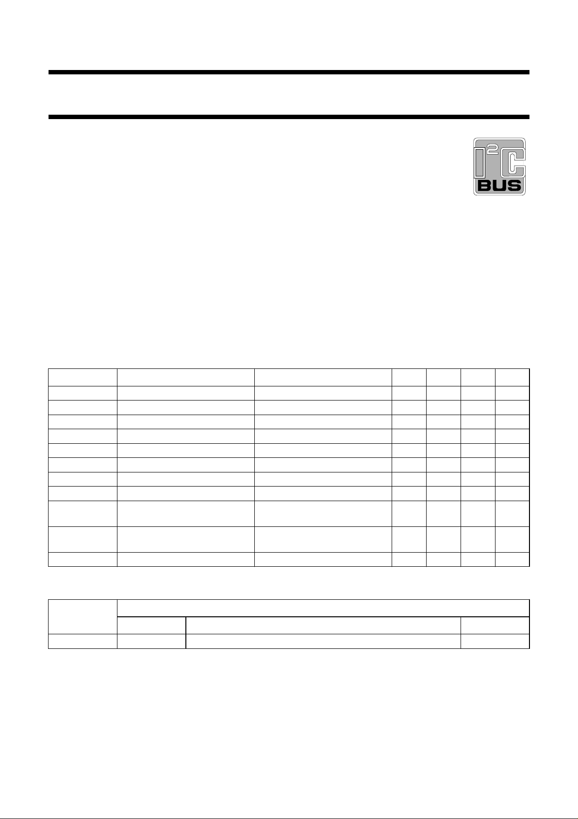
FEATURES
• Source selector for four stereo and one mono inputs
• Interface for noise reduction circuits
• Interface for external equalizer
• Volume, balance and fader control
• Special loudness characteristic automatically controlled
in combination with volume setting
• Bass control with equalizer filters
• Treble control
• Mute control at audio signal zero crossing
2
• Fast mute control via I
C-bus
• Fast mute control via pin
• I2C-bus control for all functions
• Power supply with internal power-on reset.
GENERAL DESCRIPTION
The sound fader control circuit TEA6321 is an I
2
C-bus
controlled stereo preamplifier for car radio hi-fi sound
applications.
QUICK REFERENCE DATA
SYMBOL PARAMETER CONDITIONS MIN. TYP. MAX. UNIT
V
CC
I
CC
V
o(rms)
G
v
G
step(vol)
G
bass
G
treble
G
step(treble)
(S+N)/N signal-plus-noise to noise ratio V
supply voltage 7.5 8.5 9.5 V
supply current VCC= 8.5 V − 26 − mA
maximum output voltage level VCC= 8.5 V; THD ≤ 0.1% − 2000 − mV
voltage gain −86 − +20 dB
step resolution (volume) − 1 − dB
bass control −18 − +18 dB
treble control −12 − +12 dB
step resolution (treble) − 1.5 − dB
= 2.0 V; Gv= 0 dB;
o
− 105 − dB
unweighted
RR
100
ripple rejection V
< 200 mV; f = 100 Hz;
r(rms)
− 75 − dB
Gv=0dB
α
cs
channel separation 250 Hz ≤ f ≤ 10 kHz; Gv=0dB 90 96 − dB
ORDERING INFORMATION
TYPE
NUMBER
NAME DESCRIPTION VERSION
PACKAGE
TEA6321T SO32 plastic small outline package; 32 leads; body width 7.5 mm SOT287-1
1995 Dec 19 2
Page 3
1995 Dec 19 3
BLOCK DIAGRAM
Philips Semiconductors Preliminary specification
Sound fader control circuit TEA6321
C
8.2 nF
20 kΩ
C
KVL
220 nF
2.2 kΩ
150 nF
270 nF
3.4 k
270 nF
Ω
5.6 nF
m
10 nF
MUTE
input
left
source
input
mono
source
input
right
source
GND
100 µF
V
CC
47 µF
9 x 220 nF
C
KIN
V
ref
21
31
19
16
15
13
11
14
22
20
18
17
POWER
SUPPLY
2
10 8
SOURCE
SELECTOR
23 25
C
KVL
8.2 nF
220 nF
20 kΩ
9
VOLUME I
+20 to −31 dB
LOUDNESS
LEFT
VOLUME I
+20 to −31 dB
LOUDNESS
RIGHT
24
150 nF
2.2 kΩ
7
6
BASS
LEFT
±18 dB
LOGIC
BASS
RIGHT
±18 dB
26 27
270 nF 270 nF
3.4 k
512
MUTE
FUNCTION
ZERO CROSS
DETECTOR
TREBLE
LEFT
±12 dB
TREBLE
RIGHT
±12 dB
TEA6321
28
Ω
5.6 nF
VOLUME II
0 to −55 dB
BALANCE
FADER REAR
VOLUME II
0 to −55 dB
BALANCE
FADER FRONT
I2C-BUS
RECEIVER
VOLUME II
0 to −55 dB
BALANCE
FADER FRONT
VOLUME II
0 to −55 dB
BALANCE
FADER REAR
32
29
30
MED838
3
output
left
4
SCL
1
SDA
output
right
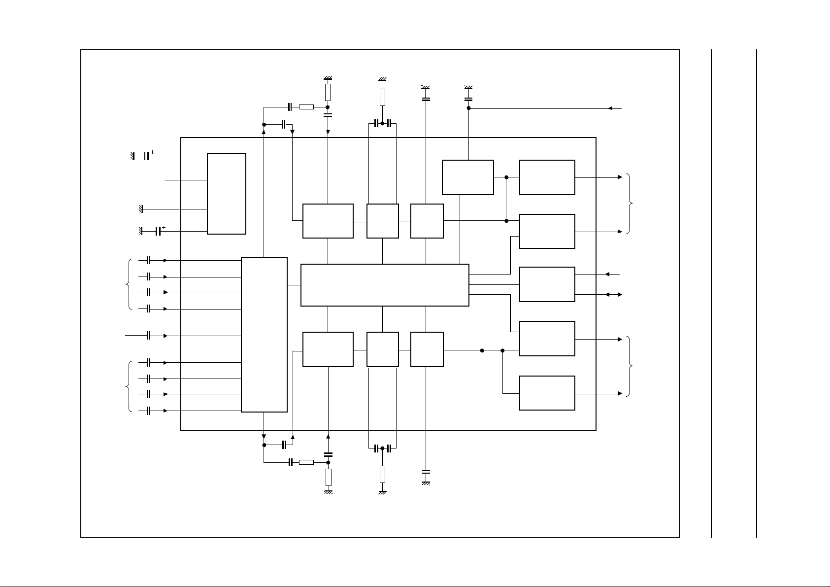
Fig.1 Block diagram.
handbook, full pagewidth
Page 4
Philips Semiconductors Preliminary specification
Sound fader control circuit TEA6321
PINNING
SYMBOL PIN DESCRIPTION
SDA 1 serial data input/output
GND 2 ground
OUTLR 3 output left rear
OUTLF 4 output left front
TL 5 treble control capacitor left channel
or input from an external equalizer
B2L 6 bass control left channel or output to
an external equalizer
B1L 7 bass control, left channel
IVL 8 input volume I, left control part
ILL 9 input loudness, left control part
QSL 10 output source selector, left channel
IDL 11 input D left source
MUTE 12 mute control
ICL 13 input C left source
IMO 14 input mono source
IBL 15 input B left source
IAL 16 input A left source
IAR 17 input A right source
IBR 18 input B right source
CAP 19 electronic filtering for supply
ICR 20 input C right source
V
ref
21 reference voltage (0.5VCC)
IDR 22 input D right source
QSR 23 output source selector right channel
ILR 24 input loudness right channel
IVR 25 input volume I, right control part
B1R 26 bass control right channel
B2R 27 bass control right channel or output
to an external equalizer
TR 28 treble control capacitor right channel
or input from an external equalizer
OUTRF 29 output right front
OUTRR 30 output right rear
V
CC
31 supply voltage
SCL 32 serial clock input
handbook, halfpage
1
SDA
2
GND
TL
B2L
B1L
IVL
ILL
QSL
IDL
MUTE
ICL
IMO
IBL
IAL
3
4
5
6
7
8
9
10
11
12
13
14
15
16
TEA6321
MED839
OUTLR
OUTLF
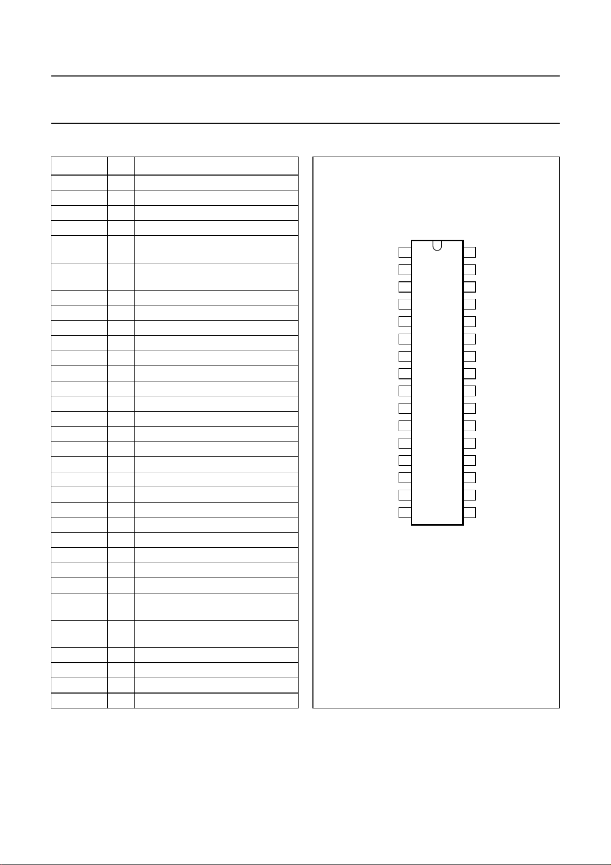
Fig.2 Pin configuration.
32
31
30
29
28
27
26
25
24
23
22
21
20
19
18
17
SCL
V
CC
OUTRR
OUTRF
TR
B2R
B1R
IVR
ILR
QSR
IDR
V
ref
ICR
CAP
IBR
IAR
1995 Dec 19 4
Page 5

Philips Semiconductors Preliminary specification
Sound fader control circuit TEA6321
FUNCTIONAL DESCRIPTION
The source selector selects one of 4 stereo inputs or the
mono input. The maximum input signal voltage is
V
= 2 V. The outputs of the source selector and the
i(rms)
inputs of the following volume control parts are available at
pins 8 and 10 for the left channel and pins 23 and 25 for
the right channel. This offers the possibility of interfacing a
noise reduction system.
The volume control function is split into two sections:
volume I control block and volume II control block.
The control range of volume I is between +20 dB and
−31 dB in steps of 1 dB. The volume II control range is
between 0 dB and −55 dB in steps of 1 dB. Although the
theoretical possible control range is 106 dB
(+20 to −86 dB), in practice a range of 86 dB
(+20 to −66 dB) is recommended. The gain/attenuation
setting of the volume I control block is common for both
channels.
The volume I control block operates in combination with
the loudness control. The filter is linear when the maximum
gain for the volume I control (+20 dB) is selected. The filter
characteristic increases automatically over a range of
32 dB down to a setting of −12 dB. That means the
maximum filter characteristic is obtained at −12 dB setting
of volume I. Further reduction of the volume does not
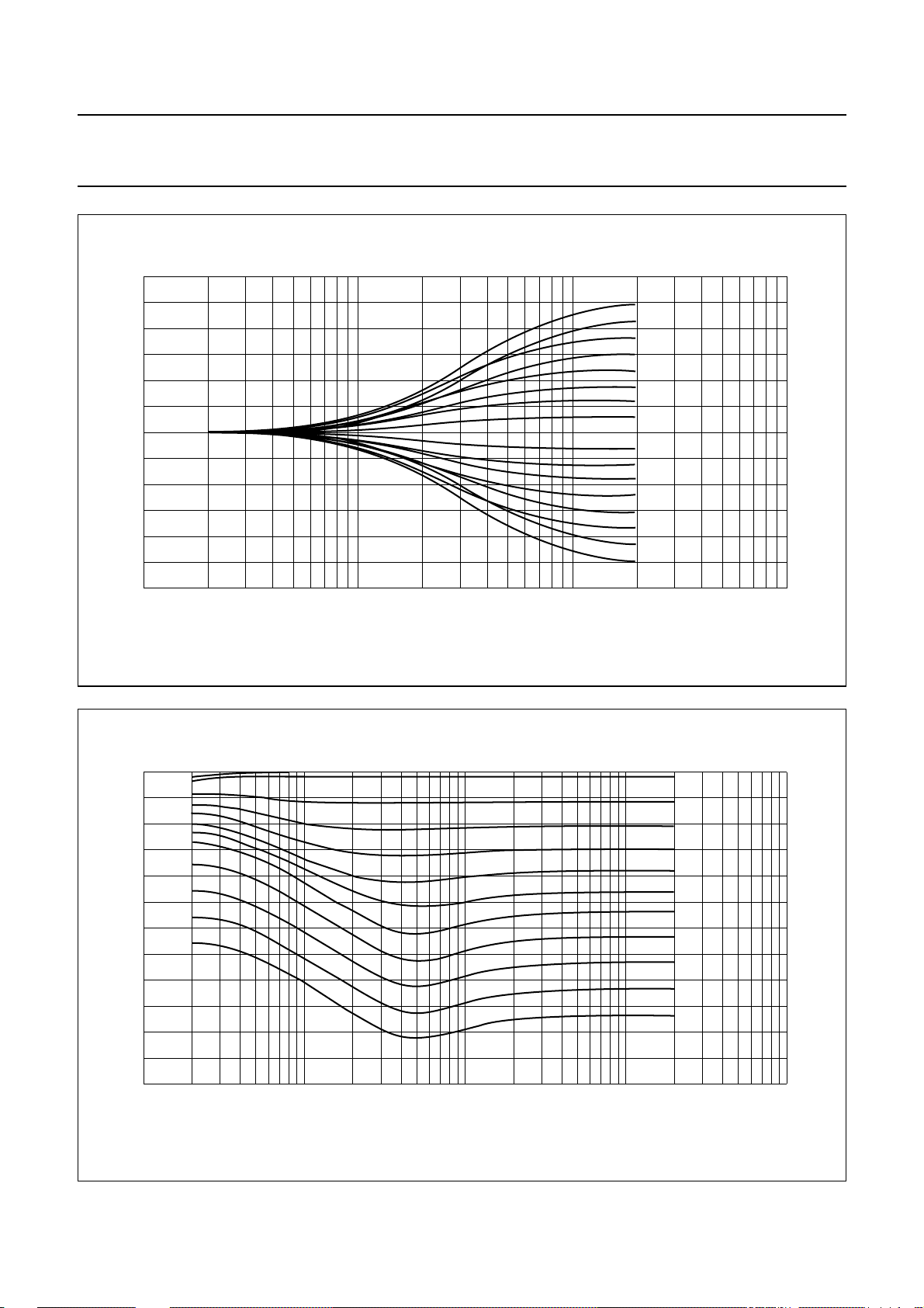
further influence the filter characteristic (see Fig.5). The
maximum selected filter characteristic is determined by
external components. The proposed application gives a
maximum boost of 17 dB for bass and 4.5 dB for treble.
2
The loudness may be switched on or off via I
C-bus control
(see Table 7).
The volume I control block is followed by the bass control
block. An external filter for each channel in combination
with internal resistors, provides the frequency response of
the bass control (see Fig.3). The adjustable range is
between −18 and +18 dB in steps of 1.8 dB at 46 Hz.
Both loudness and bass control result in a maximum bass
boost of 35 dB for low volume settings.
The treble control block offers a control range between
−12 and +12 dB in steps of 1.5 dB at 15 kHz. The filter
characteristic is determined by a single capacitor of 5.6 nF
for each channel in combination with internal resistors
(see Fig.4).
The basic step width of treble control is 3 dB. The
intermediate steps are obtained by switching 1.5 dB boost
and 1.5 dB attenuation steps.
The bass and treble control functions can be switched off
via I2C-bus. In this event the internal signal flow is
disconnected. The connections B2L and B2R are outputs
and TL and TR are inputs for inserting an external
equalizer.
The last section of the circuit is the volume II block. The
balance and fader functions are performed using the same
control blocks. This is realized by 4 independently
controllable attenuators, one for each output. The control
range of these attenuators is 55 dB in steps of 1 dB with an
additional mute step.
The circuit provides 3 mute modes:
2
1. Zero crossing mode mute via I
C-bus using
2 independent zero crossing detectors (ZCM,
see Tables 2 and 9 and Fig.16).
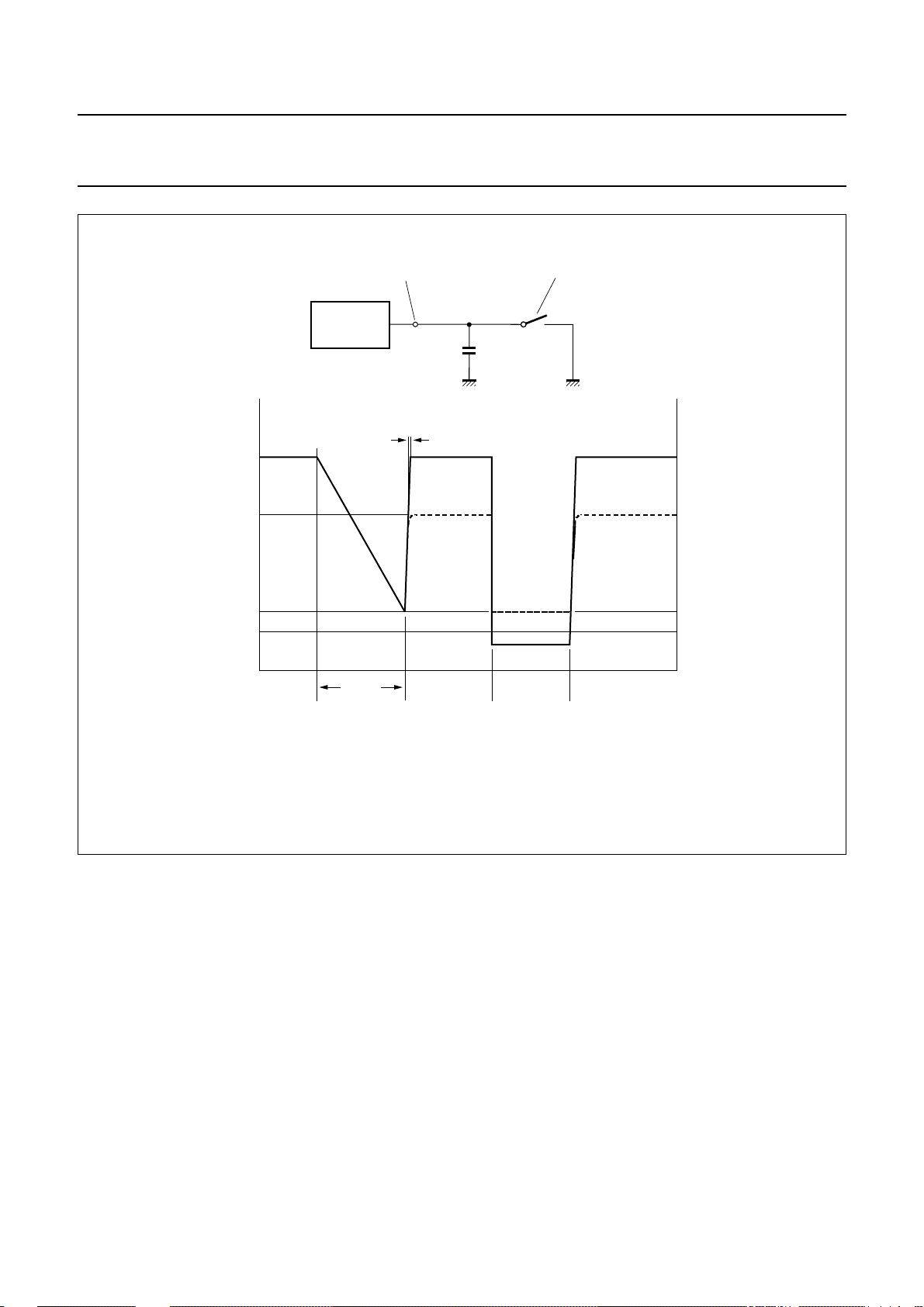
2. Fast mute via MUTE pin (see Fig.10).
3. Fast mute via I2C-bus either by general mute (GMU,
see Tables 2 and 9) or volume II block setting
(see Table 4).
The mute function is performed immediately if ZCM is
cleared (ZCM = 0). If the bit is set (ZCM = 1) the mute is
activated after changing the GMU bit. The actual mute
switching is delayed until the next zero crossing of the
audio frequency signal. As the two audio channels (left and
right) are independent, two comparators are built-in to
control independent mute switches.
To avoid a large delay of mute switching when very low
frequencies are processed, the maximum delay time is
limited to typically 100 ms by an integrated timing circuit
and an external capacitor (Cm= 10 nF, see Fig.10). This
timing circuit is triggered by reception of a new data word
for the switch function which includes the GMU bit. After a
discharge and charge period of an external capacitor the
muting switch follows the GMU bit if no zero crossing was
detected during that time.
The mute function can also be controlled externally. If the
mute pin is switched to ground all outputs are muted
immediately (hardware mute). This mute request
overwrites all mute controls via the I2C-bus for the time the
pin is held LOW. The hardware mute position is not stored
in the TEA6321.
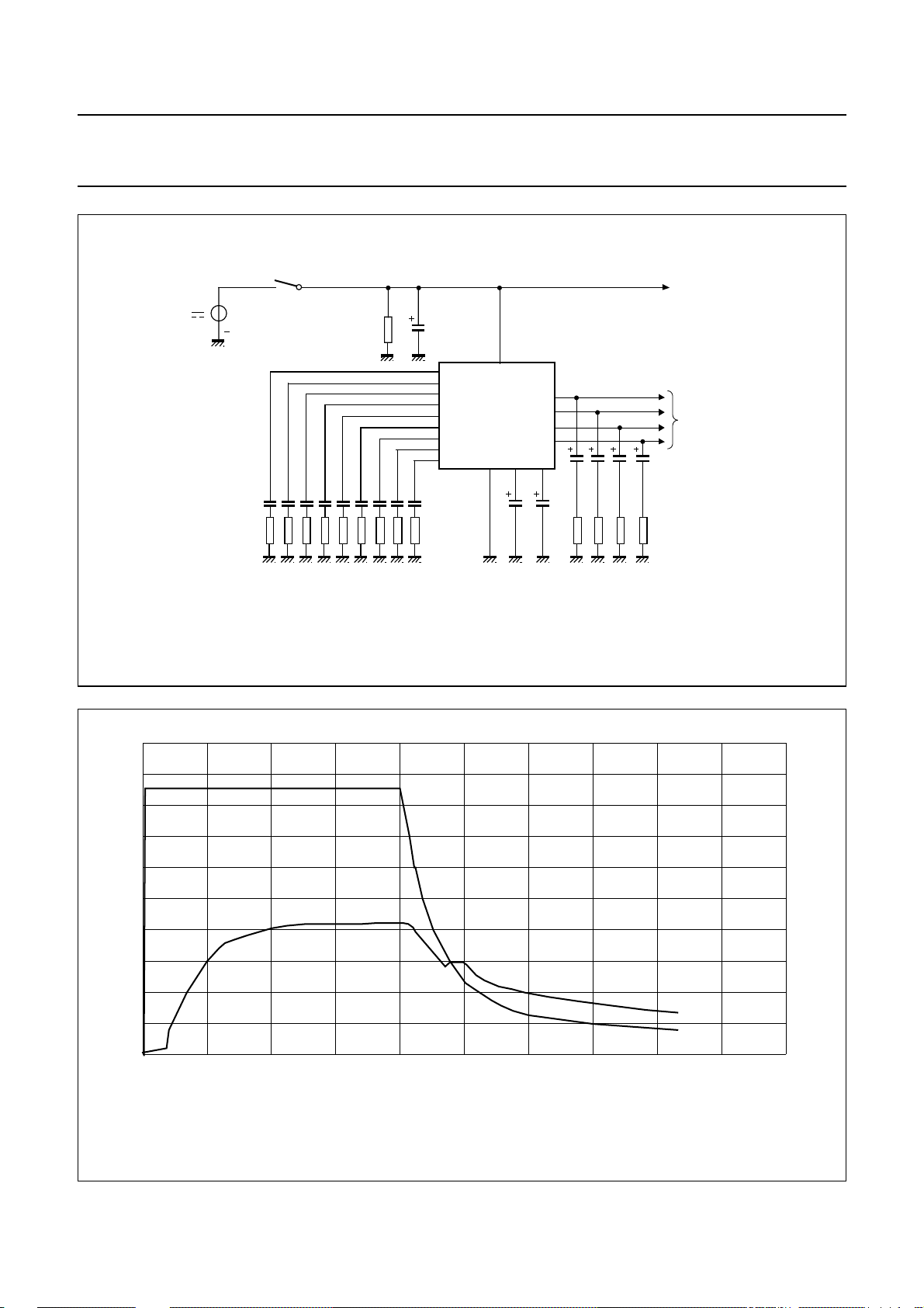
For the turn on/off behaviour the following explanation is
generally valid. To avoid AF output caused by the input
signal coming from preceding stages, which produces
output during drop of VCC, the mute has to be set before
the VCC will drop. This can be achieved by I2C-bus control
or by grounding the MUTE pin.
For use where is no mute in the application before turn off,
a supply voltage drop of more than 1 × VBE will result in a
mute during the voltage drop.
1995 Dec 19 5
Page 6

Philips Semiconductors Preliminary specification
Sound fader control circuit TEA6321
The power supply should include a VCC buffer capacitor,
which provides a discharging time constant. If the input
signal does not disappear after turn off the input will
become audible after certain time. A 4.7 kΩ resistor
discharges the VCC buffer capacitor, because the internal
The hardware mute function is favourable for use in Radio
Data System (RDS) applications. The zero crossing mute
avoids modulation plops. This feature is an advantage for
mute during changing presets and/or sources (e.g. traffic
announcement during cassette playback).
current of the IC does not discharge it completely.
LIMITING VALUES
In accordance with the Absolute Maximum Rating System (IEC 134).
SYMBOL PARAMETER CONDITIONS MIN. MAX. UNIT
V
CC
V
n
supply voltage 0 10 V
voltage at pins 1 and 3 to 32 to
0VCCV
pin 2
T
amb
T
stg
V
es
operating ambient temperature −40 +85 °C
storage temperature −65 +150 °C
electrostatic handling note 1
Note
1. Human body model: C = 100 pF; R = 1.5 kΩ; V ≥ 2 kV. Charge device model: C = 200 pF; R = 0 Ω; V ≥ 500 V.
1995 Dec 19 6
Page 7

Philips Semiconductors Preliminary specification
Sound fader control circuit TEA6321
CHARACTERISTICS
VCC= 8.5 V; RS= 600 Ω; RL=10kΩ; CL= 2.5 nF; AC coupled; f = 1 kHz; T
linear; treble linear; fader off; balance in mid position; loudness off; unless otherwise specified.
SYMBOL PARAMETER CONDITIONS MIN. TYP. MAX. UNIT
V
CC
I
CC
V
DC
supply voltage 7.5 8.5 9.5 V
supply current − 26 33 mA
internal DC voltage at inputs and
outputs
V
ref
G
V
o(rms)
v(max)
internal reference voltage at pin 21 − 4.25 − V
maximum voltage gain RS=0Ω; RL= ∞ 19 20 21 dB
output voltage level for
at the power output stage THD ≤ 0.1%; see Fig.11 − 2000 − mV
P
max
start of clipping THD = 1% 2300 −−mV
R
=2kΩ; CL= 10 nF;
L
THD=1%
V
f
ro
i(rms)
input sensitivity Vo= 2000 mV; Gv=20dB − 200 − mV
roll-off frequency C
= 220 nF;
KIN
C
= 220 nF; Zi=Z
KVL
low frequency (−1 dB) 60 −−Hz
low frequency (−3 dB) 30 −−Hz
high frequency (−1 dB) 20000 −−Hz
C
= 470 nF;
KIN
C
= 100 nF; Zi=Z
KVL
low frequency (−3 dB)
α
cs
channel separation Vi= 2 V; frequency range
250 Hz to 10 kHz
THD total harmonic distortion frequency range
20 Hz to 12.5 kHz
Vi= 100 mV; Gv=20dB − 0.1 − %
V
= 1 V; Gv=0dB − 0.05 0.15 %
i
V
= 2 V; Gv=0dB − 0.1 − %
i
= 2 V; Gv= −10 dB − 0.1 − %
V
i
RR ripple rejection V
r(rms)
< 200 mV
f = 100 Hz 70 76 − dB
f = 40 Hz to 12.5 kHz − 66 − dB
(S+N)/N signal-plus-noise to noise ratio unweighted;
20 Hz to 20 kHz RMS;
V
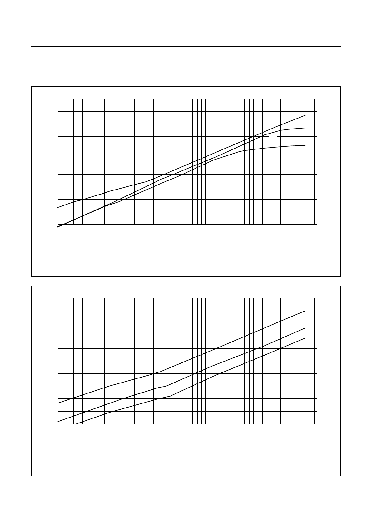
= 2.0 V; see Figs 6 and 7
o
CCIR468-2 weighted; quasi
peak; V
= 2.0 V
o
G
=0dB − 95 − dB
v
=12dB − 88 − dB
G
v
G
=20dB − 81 − dB
v
=25°C; gain control Gv= 0 dB; bass
amb
3.83 4.25 4.68 V
2000 −−mV
i(min)
17 −−Hz
i(typ)
90 96 − dB
− 105 − dB
1995 Dec 19 7
Page 8
Philips Semiconductors Preliminary specification
Sound fader control circuit TEA6321
SYMBOL PARAMETER CONDITIONS MIN. TYP. MAX. UNIT
P
no(rms)
α
ct
Source selector
Z
i
α
S
V
i(rms)
V
offset
Z
o
R
L
C
L
G
v
Control part (source selector disconnected; source resistance 600 Ω)
Z
i
Z
o
R
L
C
L
R
DCL
V
i(rms)
V
no
CR
tot
G
step
noise output power (RMS value)
mute position; note 1 −−10 nW
only contribution of TEA6321;
power amplifier for 6 W
crosstalk
V
20
bus p p–()
-------------------------- -log
V
o rms()
between bus
note 2 − 110 − dB
inputs and signal outputs
input impedance 25 35 45 kΩ
input isolation of one selected
source to any other input
maximum input voltage
(RMS value)
DC offset voltage at source
f = 1 kHz − 105 − dB
f = 12.5 kHz − 95 − dB
THD < 0.5%; VCC= 8.5 V − 2.15 − V
THD < 0.5%; V
= 7.5 V − 1.8 − V
CC
−−10 mV
selector output by selection of any
inputs
output impedance − 80 120 Ω
output load resistance 10 −−kΩ
output load capacity 0 − 2500 pF
voltage gain, source selector − 0 − dB
input impedance volume input 100 150 200 kΩ
input impedance loudness input 25 33 40 kΩ
output impedance − 80 120 Ω
output load resistance 2 −−kΩ
output load capacity 0 − 10 nF
DC load resistance at output to
4.7 −−kΩ
ground
maximum input voltage
THD < 0.5% − 2.15 − V
(RMS value)
noise output voltage CCIR468-2 weighted; quasi
peak
G
=20dB − 110 220 µV
v
G
=0dB − 33 50 µV
v
G
= −66 dB − 13 22 µV
v
mute position − 10 −µV
total continuous control range − 106 − dB
recommended control range − 86 − dB
step resolution − 1 − dB
step error between any adjoining
−−0.5 dB
step
1995 Dec 19 8
Page 9
Philips Semiconductors Preliminary specification
Sound fader control circuit TEA6321
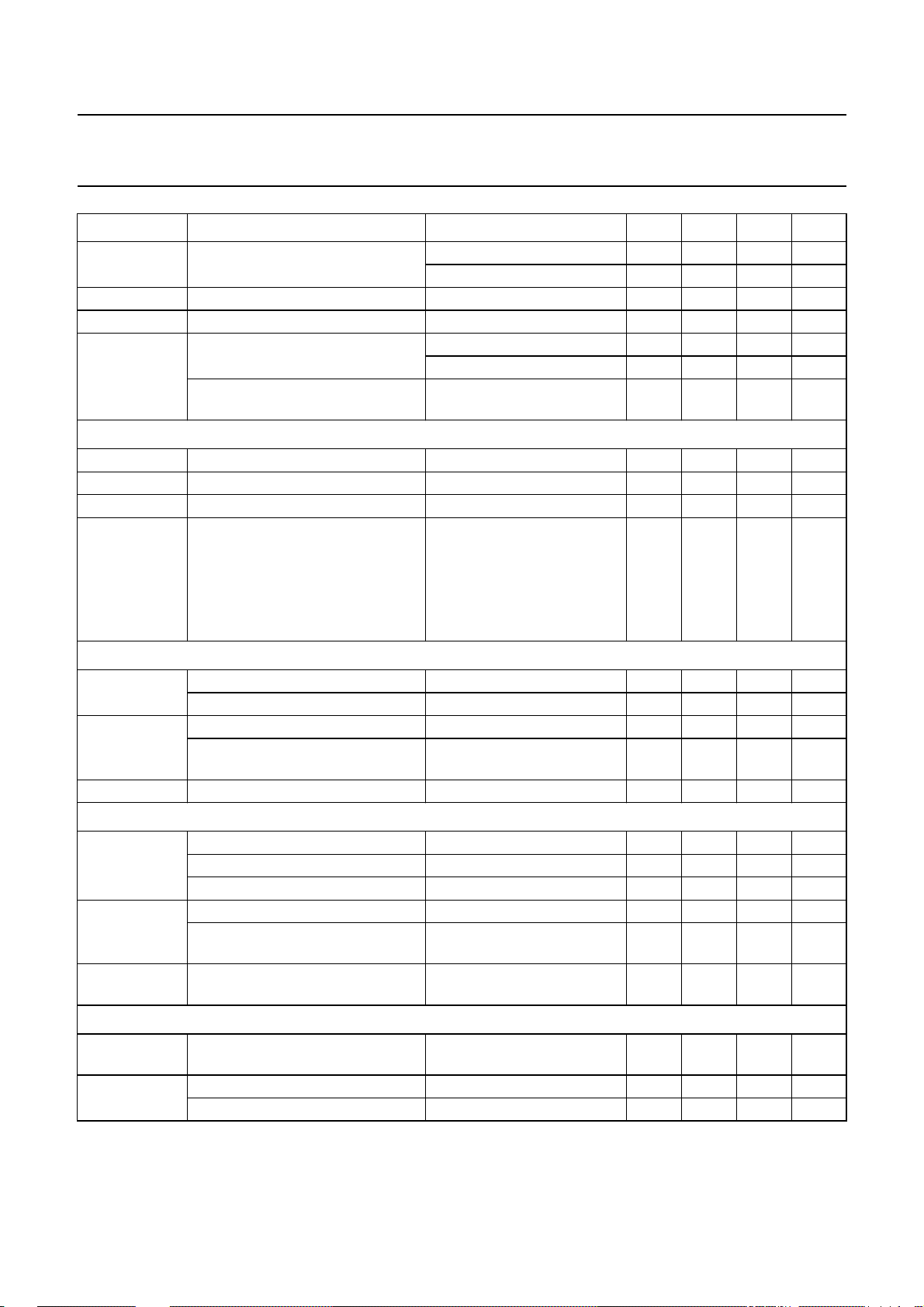
SYMBOL PARAMETER CONDITIONS MIN. TYP. MAX. UNIT
∆G
a
∆G
t
MUTE
att
V
offset
Volume I control and loudness
CR
vol
G
v
G
step
L
Bmax
attenuator set error Gv= +20 to −50 dB −−2dB
G
=−51 to −66 dB −−3dB
v
gain tracking error Gv= +20 to −50 dB −−2dB
mute attenuation see Fig.10 100 110 − dB
DC step offset between any
adjoining step
DC step offset between any step to
Gv=0to−66 dB − 0.2 10 mV
G
=20to0dB − 215mV
v
=0to−66 dB −−10 mV
G
v
mute
continuous volume control range − 51 − dB
voltage gain −31 − +20 dB
step resolution − 1 − dB
maximum loudness boost loudness on; referred to
loudness off; boost is
determined by external
components
f = 40 Hz − 17 − dB
f = 10 kHz − 4.5 − dB
Bass control
G
bass
bass control, maximum boost f = 46 Hz 16 18 19 dB
maximum attenuation f = 46 Hz 16 18 19 dB
G
step
step resolution (toggle switching) f = 46 Hz − 1.8 − dB
step error between any adjoining
step
V
offset
DC step offset in any bass position −−20 mV
Treble control
G
treble
treble control, maximum boost f = 15 kHz 11 12 13 dB
maximum attenuation f = 15 kHz 11 12 13 dB
maximum boost f > 15 kHz −−15 dB
G
step
step resolution (toggle switching) f = 15 kHz − 1.5 − dB
step error between any adjoining
step
V
offset
DC step offset in any treble
position
Volume II, balance and fader control
CR continuous attenuation fader and
volume control range
G
step
step resolution − 12dB
attenuation set error −−1.5 dB
f = 46 Hz −−0.5 dB
f = 15 kHz −−0.5 dB
−−10 mV
53.5 55 56.5 dB
1995 Dec 19 9
Page 10
Philips Semiconductors Preliminary specification
Sound fader control circuit TEA6321
SYMBOL PARAMETER CONDITIONS MIN. TYP. MAX. UNIT
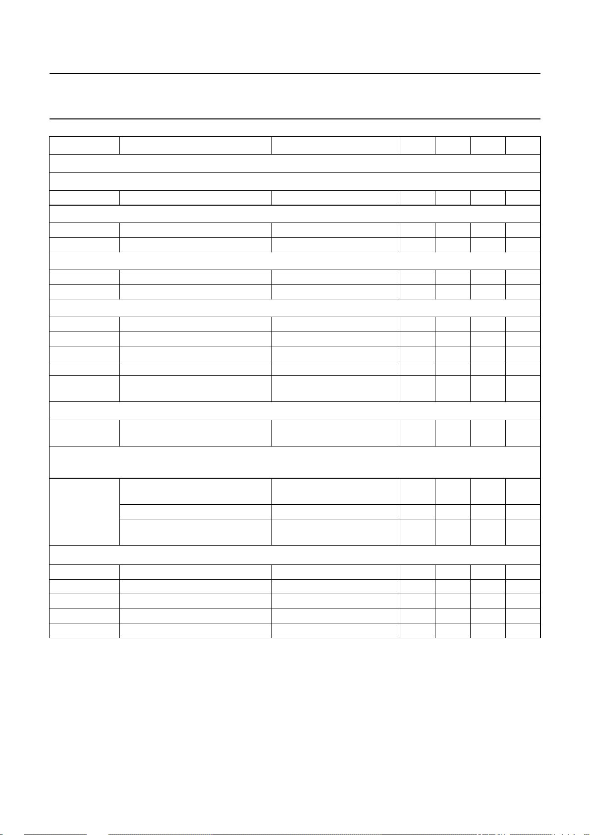
Mute function (see Fig.10)
ARDWARE MUTE
H
V
sw
mute active
V
swLOW
I
i
mute passive: level internally defined
V
swHIGH
t
d(mute)
ZERO CROSSING MUTE
I
d
I
ch
V
swDEL
t
d
V
wind
mute switch level (2 × VBE) − 1.45 − V
input level −−1.0 V
input current V
=1V −300 −−µA
swLOW
saturation voltage −−VCCV
delay until mute passive −−0.5 ms
discharge current 0.3 0.6 1.2 µA
charge current −300 −150 −µA
delay switch level (3 × VBE) − 2.2 − V
delay time Cm=10nF − 100 − ms
window for audio signal zero
− 30 40 mV
crossing detection
Muting at power supply drop
V
CCdrop
supply drop for mute active − V19−
− V
0.7
2
Power-on reset (when reset is active the GMU-bit (general mute) is set and the I
C-bus receiver is in reset
position)
V
CC
increasing supply voltage start of
−−2.5 V
reset
end of reset 5.2 6.5 7.2 V
decreasing supply voltage start of
4.2 5.5 6.2 V
reset
Digital part (I
V
iH
V
iL
I
iH
I
iL
V
oL
2
C-bus pins); note 3
HIGH level input voltage 3 − 9.5 V
LOW level input voltage −0.3 − +1.5 V
HIGH level input current −10 − +10 µA
LOW level input current −10 − +10 µA
LOW level output voltage IL=3mA −−0.4 V
Notes to the characteristics
1. The indicated values for output power assume a 6 W power amplifier at 4 Ω with 20 dB gain and a fixed attenuator
of 12 dB in front of it. Signal-to-noise ratios exclude noise contribution of the power amplifier.
2. The transmission contains: total initialization with MAD and subaddress for volume and 8 data words, see also
definition of characteristics, clock frequency = 50 kHz, repetition burst rate = 400 Hz, maximum bus signal
amplitude = 5 V (p-p).
3. The AC characteristics are in accordance with the I2C-bus specification. This specification,
use it”
, can be ordered using the code 9398 393 40011.
“The I2C-bus and how to
1995 Dec 19 10
Page 11

Philips Semiconductors Preliminary specification
Sound fader control circuit TEA6321
I2C-BUS PROTOCOL
2
C-bus format
I
(1)
S
SLAVE ADDRESS
Notes
1. S = START condition.
2. SLAVE ADDRESS (MAD) = 1000 0000.
3. A = acknowledge, generated by the slave.
4. SUBADDRESS (SAD), see Table 1.
5. DATA, see Table 1.
6. P = STOP condition.
Table 1 Second byte after MAD.
(2)
(3)
A
SUBADDRESS
(4)
(3)
A
DATA
(5)
(3)
A
(6)
P
FUNCTION BIT
765432
(1)
(1)
1
(1)
0
Volume/loudness V 00000000
Fader front right FFR 00000001
Fader front left FFL 00000010
Fader rear right FRR 00000011
Fader rear left FRL 00000100
Bass BA 00000101
Treble TR 00000110
Switch S 00000111
Note
1. Significant subaddress.
MSB LSB
1995 Dec 19 11
Page 12

Philips Semiconductors Preliminary specification
Sound fader control circuit TEA6321
Table 2 Definition of third byte after MAD and SAD
FUNCTION BIT
MSB LSB
76543210
Volume/loudness V ZCM
Fader front right FFR X
Fader front left FFL X
Fader rear right FRR X
Fader rear left FRL X
Bass BA X
Treble TR X
Switch S GMU
(1)
(4)
(4)
(4)
(4)
(4)
(4)
(11)
LOFF
(4)
X
(4)
X
(4)
X
(4)
X
(4)
X
(4)
X
(4)
X
(2)
V5
FFR5
FFL5
FRR5
FRL5
(4)
X
(4)
X
(4)
X
(3)
(6)
(8)
(5)
(7)
V4
FFR4
FFL4
FRR4
FRL4
BA4
TR4
(4)
X
(3)
(5)
(6)
(7)
(8)
(9)
(10)
Notes
1. Zero crossing mode.
2. Switch loudness on/off.
3. Volume control.
4. Don’t care bits (logic 1 during testing).
5. Fader control front right.
6. Fader control front left.
7. Fader control rear right.
8. Fader control rear left.
9. Bass control.
10. Treble control.
11. Mute control for all outputs except the outputs OVL and OVR (general mute).
12. Source selector control.
V3
FFR3
FFL3
FRR3
FRL3
BA3
TR3
(4)
X
(3)
(9)
(10)
(6)
(5)
(7)
(8)
V2
FFR2
FFL2
FRR2
FRL2
BA2
TR2
SC2
(3)
(9)
(10)
(12)
(5)
(6)
(8)
(7)
V1
FFR1
FFL1
FRR1
FRL1
BA1
TR1
SC1
(3)
(10)
(12)
(9)
(6)
(8)
(5)
(7)
V0
FFR0
FFL0
FRR0
FRL0
BA0
TR0
SC0
(3)
(5)
(6)
(7)
(8)
(9)
(10)
(12)
1995 Dec 19 12
Page 13

Philips Semiconductors Preliminary specification
Sound fader control circuit TEA6321
Table 3 Volume I setting
G
v
(dB)
Loudness on: the increment of the loudness characteristics is linear at every volume step in the range from
+20 to −11 dB
+20 111111
+19 111110
+18 111101
+17 111100
+16 111011
+15 111010
+14 111001
+13 111000
+12 110111
+11 110110
+10 110101
+9 110100
+8 110011
+7 110010
+6 110001
+5 110000
+4 101111
+3 101110
+2 101101
+1 101100
0 101011
−1 101010
−2 101001
−3 101000
−4 100111
−5 100110
−6 100101
−7 100100
−8 100011
−9 100010
−10 100001
−11 100000
V5 V4 V3 V2 V1 V0
DATA
1995 Dec 19 13
Page 14
Philips Semiconductors Preliminary specification
Sound fader control circuit TEA6321
G
v
(dB)
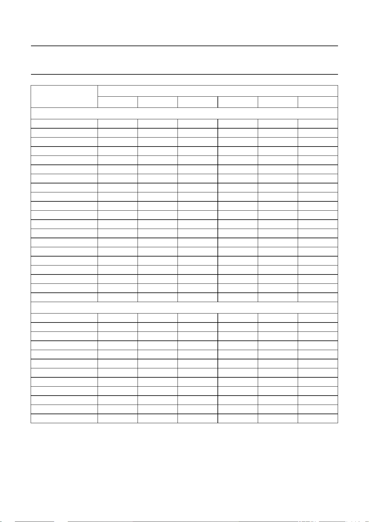
Loudness characteristic is constant in a range from −11 dB to −31 dB
−12 011111
−13 011110
−14 011101
−15 011100
−16 011011
−17 011010
−18 011001
−19 011000
−20 010111
−21 010110
−22 010101
−23 010100
−24 010011
−25 010010
−26 010001
−27 010000
−28 001111
−29 001110
−30 001101
−31 001100
V5 V4 V3 V2 V1 V0
DATA
Repetition of steps in a range from −28 dB to −31 dB
−28 001011
−29 001010
−30 001001
−31 001000
−28 000111
−29 000110
−30 000101
−31 000100
−28 000011
−29 000010
−30 000001
−31 000000
1995 Dec 19 14
Page 15

Philips Semiconductors Preliminary specification
Sound fader control circuit TEA6321
Table 4 Volume II setting (fader and balance); note 1
DATA
FRR5 FRR4 FRR3 FRR2 FRR1 FRR0
G
v
(dB)
0 111111
−1 111110
−2 111101
−3 111100
−4 111011
−5 111010
−6 111001
−7 111000
−8 110111
−9 110110
−10 110101
−11 110100
−12 110011
−13 110010
−14 110001
−15 110000
−16 101111
−17 101110
−18 101101
−19 101100
−20 101011
−21 101010
−22 101001
−23 101000
−24 100111
−25 100110
−26 100101
−27 100100
−28 100011
−29 100010
−30 100001
−31 100000
−32 011111
−33 011110
−34 011101
FRL5 FRL4 FRL3 FRL2 FRL1 FRL0
FFL5 FFL4 FFL3 FFL2 FFL1 FFL0
FFR5 FFR4 FFR3 FFR2 FFR1 FFR0
1995 Dec 19 15
Page 16

Philips Semiconductors Preliminary specification
Sound fader control circuit TEA6321
DATA
FRR5 FRR4 FRR3 FRR2 FRR1 FRR0
G
v
(dB)
−35 011100
−36 011011
−37 011010
−38 011001
−39 011000
−40 010111
−41 010110
−42 010101
−43 010100
−44 010011
−45 010010
−46 010001
−47 010000
−48 001111
−49 001110
−50 001101
−51 001100
−52 001011
−53 001010
−54 001001
−55 001000
mute 0 0 0 1 1 1
mute 0 0 0 1 1 0
mute 0 0 0 1 0 1
mute 0 0 0 1 0 0
mute 0 0 0 0 1 1
mute 0 0 0 0 1 0
mute 0 0 0 0 0 1
mute 0 0 0 0 0 0
FRL5 FRL4 FRL3 FRL2 FRL1 FRL0
FFL5 FFL4 FFL3 FFL2 FFL1 FFL0
FFR5 FFR4 FFR3 FFR2 FFR1 FFR0
Note
1. For a particular range the data is always the same, only the subaddress changes.
1995 Dec 19 16
Page 17

Philips Semiconductors Preliminary specification
Sound fader control circuit TEA6321
Table 5 Bass setting
G
bass
(dB)
BA4 BA3 BA2 BA1 BA0
DATA
+18.0 11111
+16.2 11110
+18.0 11101
+16.2 11100
+18.0 11011
+16.2 11010
+14.4 11001
+12.6 11000
+10.8 10111
+9.0 10110
+7.2 10101
+5.4 10100
+3.6 10011
+1.8 10010
(1)
0
(2)
0
10001
10000
−1.8 01111
−3.6 01110
−5.4 01101
−7.2 01100
−9.0 01011
−10.8 01010
−12.6 01001
−14.4 01000
−16.2 00111
−18.0 00110
−16.2 00101
−18.0 00100
note 3 00011
note 3 00010
note 3 00001
notes 3 and 4 00000
Notes
1. Recommended data word for step 0 dB.
2. Result of 1.8 dB boost and 1.8 dB attenuation.
3. The last four bass control data words mute the bass response.
4. The last bass control and treble control data words (00000) enable the external equalizer connection.
1995 Dec 19 17
Page 18

Philips Semiconductors Preliminary specification
Sound fader control circuit TEA6321
Table 6 Treble setting
G
(dB)
treble
TR4 TR3 TR2 TR1 TR0
DATA
+12.0 11111
+10.5 11110
+12.0 11101
+10.5 11100
+12.0 11011
+10.5 11010
+12.0 11001
+10.5 11000
+9.0 10111
+7.5 10110
+6.0 10101
+4.5 10100
+3.0 10011
+1.5 10010
(1)
0
(2)
0
10001
10000
−1.5 01111
−3.0 01110
−4.5 01101
−6.0 01100
−7.5 01011
−9.0 01010
−10.5 01001
−12.0 01000
note 3 00111
note 3 00110
note 3 00101
note 3 00100
note 3 00011
note 3 00010
note 3 00001
notes 3 and 4 00000
Notes
1. Recommended data word for step 0 dB.
2. Result of 1.5 dB boost and 1.5 dB attenuation.
3. The last eight treble control data words select treble output.
4. The last treble control and bass control data words (00000) enable the external equalizer connection.
1995 Dec 19 18
Page 19
Philips Semiconductors Preliminary specification
Sound fader control circuit TEA6321
Table 7 Loudness setting
CHARACTERISTIC DATA LOFF
With loudness 0
Linear 1
Table 8 Selected input
DATA
FUNCTION
SC2 SC1 SC0
Stereo inputs IAL and IAR 1 1 1
Stereo inputs IBL and IBR 1 1 0
Stereo inputs ICL and ICR 1 0 1
Stereo inputs IDL and IDR 1 0 0
Mono input IMO 0 X
(1)
Note
1. X = don’t care bits (logic 1 during testing).
20
handbook, full pagewidth
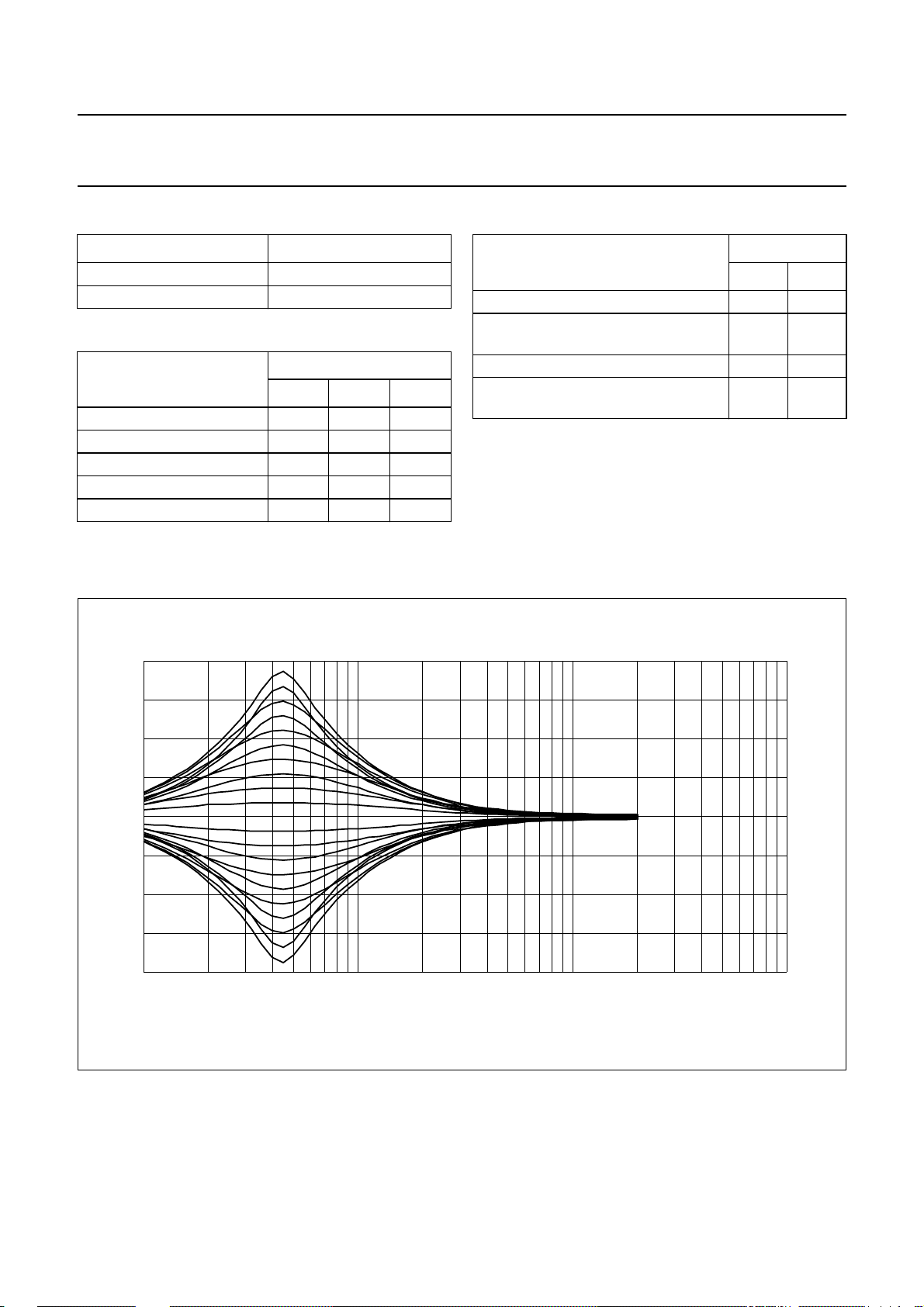
G
bass
(dB)
Table 9 Mute mode
DATA
FUNCTION
GMU ZCM
Direct mute off 0 0
Mute off delayed until the next zero
01
crossing
Direct mute 1 0
Mute delayed until the next zero
11
crossing
(1)
X
MED840
10
−10
−20
0
2
10
10
3
10
f (Hz)
4
10
Fig.3 Bass control.
1995 Dec 19 19
Page 20
Philips Semiconductors Preliminary specification
Sound fader control circuit TEA6321
15
handbook, full pagewidth
G
treble
(dB)
10
5
0
−5
−10
−15
10
32
10
Fig.4 Treble control.
MED424
4
10
f (Hz)
5
10
20
handbook, full pagewidth
G
v
(dB)
10
0
−10
−20
−30
−40
10
2
10
10
Fig.5 Volume control with loudness (including low roll-off frequency).
1995 Dec 19 20
MED425
3
4
10
f (Hz)
5
10
Page 21
Philips Semiconductors Preliminary specification
Sound fader control circuit TEA6321
100
handbook, full pagewidth
S/N
(dB)
90
80
70
60
50
−4
10
(1) Vi= 2.0V.
(2) Vi= 0.5V.
(3) Vi= 0.2V.
−3
10
−2
10
−1
10
1
Fig.6 Signal-to-noise ratio; noise weighted: CCIR468-2, quasi peak.
MED426
(1)
(2)
(3)
Po (W)
10
110
handbook, full pagewidth
S/N
(dB)
100
90
80
70
60
−4
10
(1) Unweighted RMS.
(2) CCIR468-2 RMS.
(3) CCIR468-2 quasi peak.
−3
10
−2
10
Fig.7 Signal-to-noise ratio; Vi= 2 V; P
MED427
(1)
(2)
(3)
−1
10
=6W.
max
1
Po (W)
10
1995 Dec 19 21
Page 22
Philips Semiconductors Preliminary specification
Sound fader control circuit TEA6321
200
handbook, full pagewidth
noise
(µV)
150
100
50
0
−70 −50 −30 −10 10
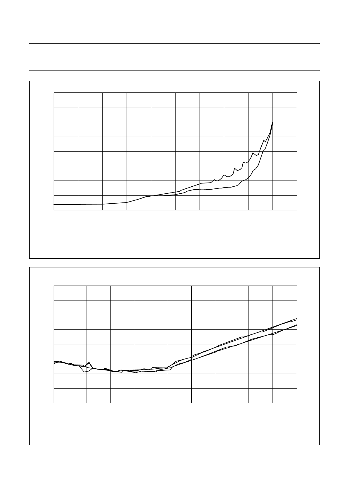
Stereo/mono inputs.
(1) Loudness on.
(2) Loudness off.
(1)
(2)
Fig.8 Noise output voltage; CCIR468-2, quasi peak.
gain (dB)
MED428
30
−60
handbook, full pagewidth
(dB)
−80
−100
−120
−140
MED429
2
10
3
10
2 x 10
3
5 x 10
3
4
10
f (Hz)
2 x 10
45020 500200
Fig.9 Muting.
1995 Dec 19 22
Page 23
Philips Semiconductors Preliminary specification
Sound fader control circuit TEA6321
handbook, full pagewidth
delay switch
mute switch
level
level
V
8.5
(1)
1.45
(V)
CC
U
2.2
TEA6321
zero crossing
mute start
hardware mute switchmute pin 12
ICH = −150 µA
ID = 0.6 µA
0.5 ms delay until
mute passive
100 ms
end of delay hard muteonhard mute
Cm = 10 nF
I
(µA)
0
−150
MED841
t (ms)
off
(1) Typically 2.2 V; referenced to 3 × V
BE
Fig.10 Mute function diagram.
1995 Dec 19 23
Page 24
Philips Semiconductors Preliminary specification
Sound fader control circuit TEA6321
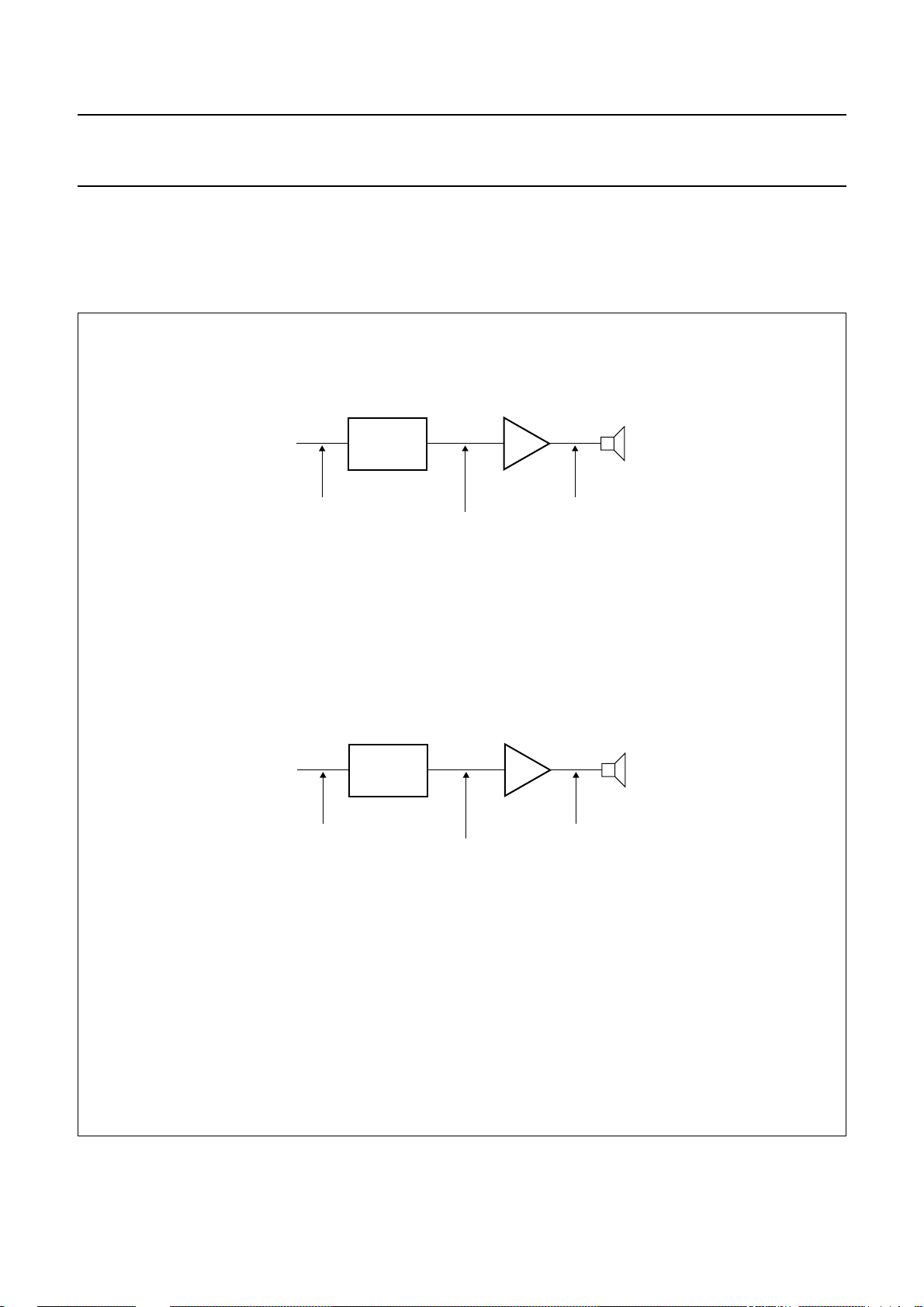
If the 20 dB gain is not required for the maximum volume
position, it will be an advantage to use the maximum boost
gain and then increased attenuation in the last section,
Volume II.
handbook, halfpage
TEA6321
= 200 mV
I(min)
Vo = 2 V for P
Therefore the loudness will be at the correct place and a
lower noise and offset voltage will be achieved.
POWER STAGE
G = 20 dB
P
= 100 W at 4 ΩV
(max)
(max)
MBE910
a.
a. Gain volume I = 20 dB (G
b. Gain volume I = 20 dB (G
handbook, halfpage
= 200 mV
I(min)
TEA6321
Vo = 1 V for P
POWER STAGE
G = 26 dB
P
= 100 W at 4 ΩV
(max)
(max)
MED842
b.
); gain volume II = 0 dB; fader and balance range = 55 dB.
v(max)
); gain volume II = −6 dB global setting; fader and balance range now 49 dB, previously 55 dB.
v(max)
Fig.11 Level diagram.
1995 Dec 19 24
Page 25
Philips Semiconductors Preliminary specification
Sound fader control circuit TEA6321
handbook, full pagewidth
+
V
8.5 V
9 × 220 nF
9 × 600 Ω
V
P
CC
4.7 kΩ
inputs
470 µF
16
15
13
11
14
17
18
20
22
31
TEA6321
21921
47
3
4
29
30
100
µFµF
+8.5 V to
oscilloscope
outputs to
oscilloscope
4 × 4.7 µF
4 × 10 kΩ
MED843
Fig.12 Turn-on/off power supply circuit diagram.
10
handbook, full pagewidth
(V)
8
6
4
2
0
01234
(1) VCC.
(2) VO.
(1)
(2)
Fig.13 Turn-on/off behaviour.
t (s)
MED433
5
1995 Dec 19 25
Page 26
Philips Semiconductors Preliminary specification
Sound fader control circuit TEA6321
handbook, full pagewidth
3.4 k
Ω
220 nF
100 µF
VCC = 8.5 V
10 kΩ
1000 µF
V
P
0.2 V (RMS)
0.1 µF
47 µF
10 8 5 12
21
31
2
19
270 nF
270 nF
5.6 nF
76
TEA6321
10 nF
32
1
SCL
SDA
handbook, full pagewidth
V
p
470 µF
600 Ω
input A to D left and right
and input mono
220 nF
23 25 28
220 nF
26 27
270 nF 270 nF
3.4 k
Ω
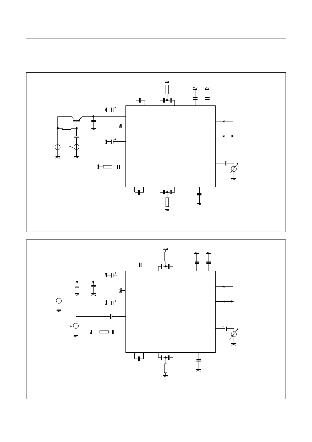
Fig.14 Test circuit for power supply ripple rejection (RR).
Ω
3.4 k
270 nF
76
TEA6321
5.6 nF
V
V
i
= 8.5 V
CC
0.1 µF
600 Ω
100 µF
47 µF
220 nF
220 nF
220 nF
10 8 5 12
21
31
2
19
input A to D right and left
input A to D left and right
and input mono
270 nF
output right
output left
front and rear
5.6 nF
output left
output right
front and rear
32
1
10 nF
4.7 µF
MED844
4.7 µF
V
SCL
SDA
O
V
O
23 25 28
220 nF
270 nF 270 nF
Fig.15 Test circuit for channel separation (αcs).
1995 Dec 19 26
26 27
3.4 k
5.6 nF
Ω
MED845
Page 27
Philips Semiconductors Preliminary specification
Sound fader control circuit TEA6321
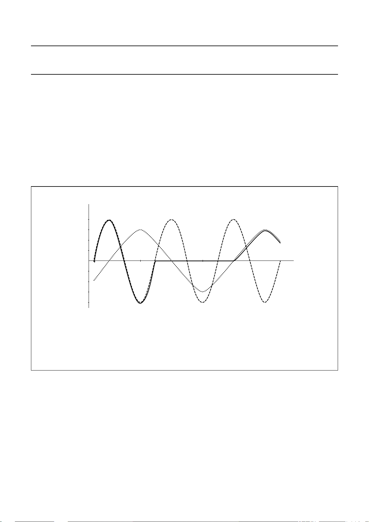
Selection of input signals by using the zero crossing
mute mode
A selection from input A (IAL) to input B (IBL) left sources
produces a modulation click depending on the difference
of the signal values at the time of switching.
At t
the maximum possible difference between signals is
1
7 V(p-p) (see Fig.16) and gives a large click. Using the
cross detector no modulation click is audible.
For example: The selection is enabled at t1, the
microcontroller sets the zero cross bit (ZCM = 1) and then
the mute bit (GMU = 1) via the I2C-bus. The output signal
handbook, full pagewidth
V
4
3
2
1
0
−1
−2
−3
t
1
follows the input A signal, until the next zero crossing
occurs and then activates mute.
After a fixed delay time at t
, the microcontroller sends the
2
bits for input switching and mute inactive.
The output signal remains muted until the next signal zero
crossing of input B (IBL) occurs, and then follows that
signal.
The delay time t2− t1 is e.g. 40 ms. Therefore the capacity
Cm= 3.3 nF. The zero cross function is working at the
lowest frequency of 40 Hz determined by the Cm capacitor.
MED436
(1)
(2)
t
2
(3)
t
(1) Input A (IAL).
(2) Output.
(3) Input B (IBL).
−4
Fig.16 Zero cross function; only one channel shown.
1995 Dec 19 27
Page 28
Philips Semiconductors Preliminary specification
h
Sound fader control circuit TEA6321
Loudness filter calculation example
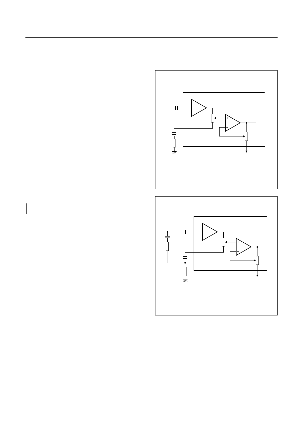
Figure 17 shows the basic loudness circuit with an
external low-pass filter application. R1 allows an
attenuation range of 21 dB while the boost is determined
by the gain stage V2. Both result in a loudness control
range of +20 to −12 dB.
Defining f
as the frequency where the level does not
ref
change while switching loudness on/off. The external
resistor R3 for f
=
R3 R1
--------------------110
→∞ can be calculated as:
ref
G
v
------ 20
10
–
. With G
G
v
------ 20
= −21 dB and R1 = 33 kΩ,
v
R3 = 3.2 kΩ is generated.
For the low-pass filter characteristic the value of the
external capacitor C1 can be determined by setting a
specific boost for a defined frequency and referring the
at f
gain to G
1
--------------------j ωC1()
as indicated above.
v
ref
R1 R3+()10
=
-------------------------------------------------------------110
–
G
------ 20
G
v
------ 20
R3–×
v
For example: 3 dB boost at f = 1 kHz
G
v=Gv(ref)
+ 3 dB = −18 dB; f = 1 kHz and C1 = 100 nF.
If a loudness characteristic with additional high frequency
boost is desired, an additional high-pass section has to be
included in the external filter circuit as indicated in the
block diagram. A filter configuration that provides
AC coupling avoids offset voltage problems.
Figure 18 shows an example of the loudness circuit with
bass and treble boost. The calculation of this network is
numeric.
handbook, halfpage
C
KVL
C1
R3
andbook, halfpage
8.2 nF
20 kΩ
150 nF
2.2 kΩ
0 dB
8
V
1
R1
33 kΩ
9
V
2
Fig.17 Basic loudness circuit.
220 nF
0 dB
8
V
1
R1
33 kΩ
9
MED846
R2
MED437
V
2
R2
Fig.18 Loudness circuit with bass and treble boost.
1995 Dec 19 28
Page 29
Philips Semiconductors Preliminary specification
Sound fader control circuit TEA6321
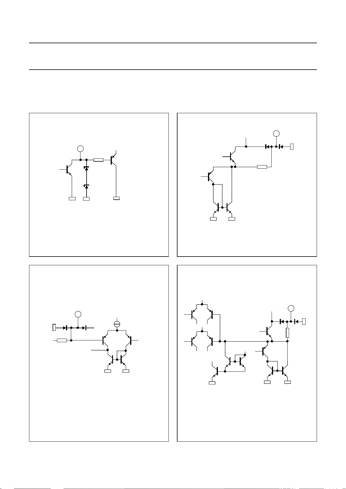
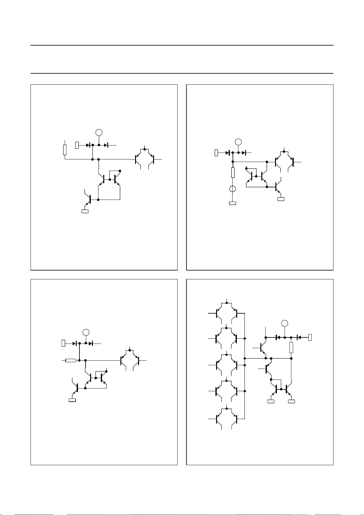
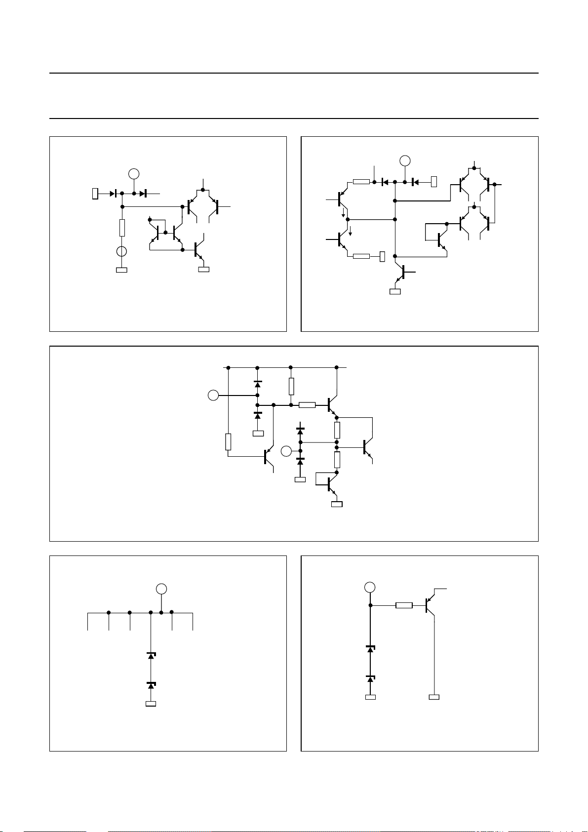
INTERNAL PIN CONFIGURATIONS
Values shown in Figs 19 to 31 are typical DC values;
VCC= 8.5 V.
3
+
1
5 V
1.8 kΩ
80 Ω
MBE911
4.25 V
Fig.19 Pin 1: SDA (I2C-bus data).
5
4.25 V
+
2.4 kΩ
+
MBE913
MBE912
Fig.20 Pins 3, 4, 29, 30: output signals.
+
6
4.25 V
80 Ω
MBE914
Fig.21 Pins 5 and 28: treble control capacitors.
1995 Dec 19 29
Fig.22 Pins 6 and 27: bass control capacitor outputs.
Page 30
Philips Semiconductors Preliminary specification
Sound fader control circuit TEA6321
7
3.52 kΩ
4.25 V
+
150 kΩ
4.25 V
MBE915
8
4.25 V
+
MED847
Fig.23 Pins 7 and 26: bass control capacitor inputs.
9
4.25 V
+
1.12 kΩ
MBE905
Fig.24 Pins 8 and 25: input volume 1, control part.
+
10
4.25 V
80 Ω
MBE906
Fig.25 Pins 9 and 24: input loudness, control part.
1995 Dec 19 30
Fig.26 Pins 10 and 23: output source selector.
Page 31
Philips Semiconductors Preliminary specification
Sound fader control circuit TEA6321
12
8.5 V
MBE908
constant
2.2 V
35 kΩ
4.25 V
11
4.25 V
+
1.3 kΩ
+
maximum
200µA
0.6 µA
constant
MBE907
4.5 kΩ
Fig.27 Pins 11, 13 to 18, 20, 22: inputs.
8.5 V
19
5 kΩ
Fig.29 Pin 19: filtering for supply; pin 21: reference voltage.
31
apply +8.5 V to this pin
4.25 V
21
4.7 kΩ
300 Ω
+
Fig.28 Pin 12: mute control.
+
3.4 kΩ
3.4 kΩ
MED439
32
5 V
1.8 kΩ
MBE909
Fig.30 Pin 31: supply voltage.
1995 Dec 19 31
MED440
Fig.31 Pin 32: SCL (I2C-bus clock).
Page 32
Philips Semiconductors Preliminary specification
Sound fader control circuit TEA6321
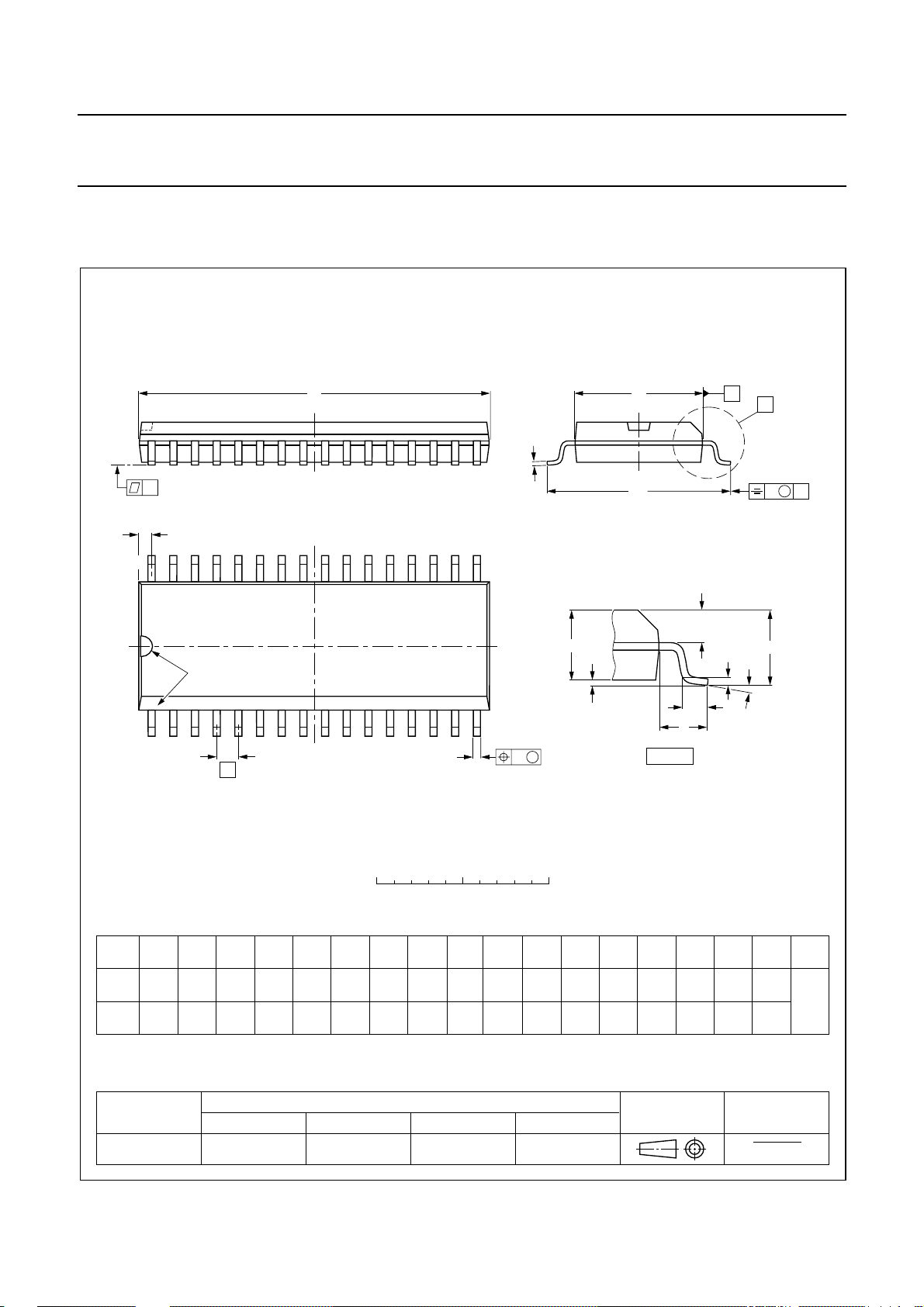
PACKAGE OUTLINE
SO32: plastic small outline package; 32 leads; body width 7.5 mm
D
c
y
Z
32
pin 1 index
1
e
17
16
w M
b
p
SOT287-1
E
H
E
A
2
A
1
L
detail X
A
X
v M
A
Q
(A )
L
p
A
3
θ
0 5 10 mm
scale
DIMENSIONS (inch dimensions are derived from the original mm dimensions)
mm
OUTLINE
VERSION
SOT287-1
A
max.
2.65
0.10
A
0.3
0.1
0.012
0.004
1
A2A3b
2.45
0.25
2.25
0.096
0.01
0.086
IEC JEDEC EIAJ
0.49
0.36
0.02
0.01
p
0.27
0.18
0.011
0.007
UNIT
inches
Note
1. Plastic or metal protrusions of 0.15 mm maximum per side are not included.
(1)E(1)
cD
20.7
20.3
0.81
0.80
REFERENCES
7.6
7.4
0.30
0.29
1.27
0.050
1995 Dec 19 32
eHELLpQZywv θ
10.65
10.00
0.419
0.394
1.4
0.055
1.1
0.4
0.043
0.016
1.2
1.0
0.047
0.039
0.25 0.1
0.25
0.010.01
EUROPEAN
PROJECTION
0.004
(1)
0.95
0.55
0.037
0.022
ISSUE DATE
95-01-25
97-05-22
o
8
o
0
Page 33

Philips Semiconductors Preliminary specification
Sound fader control circuit TEA6321
SOLDERING
Introduction
There is no soldering method that is ideal for all IC
packages. Wave soldering is often preferred when
through-hole and surface mounted components are mixed
on one printed-circuit board. However, wave soldering is
not always suitable for surface mounted ICs, or for
printed-circuits with high population densities. In these
situations reflow soldering is often used.
This text gives a very brief insight to a complex technology.
A more in-depth account of soldering ICs can be found in
our
“IC Package Databook”
Reflow soldering
Reflow soldering techniques are suitable for all SO
packages.
Reflow soldering requires solder paste (a suspension of
fine solder particles, flux and binding agent) to be applied
to the printed-circuit board by screen printing, stencilling or
pressure-syringe dispensing before package placement.
Several techniques exist for reflowing; for example,
thermal conduction by heated belt. Dwell times vary
between 50 and 300 seconds depending on heating
method. Typical reflow temperatures range from
215 to 250 °C.
(order code 9398 652 90011).
During placement and before soldering, the package must
be fixed with a droplet of adhesive. The adhesive can be
applied by screen printing, pin transfer or syringe
dispensing. The package can be soldered after the
adhesive is cured.
Maximum permissible solder temperature is 260 °C, and
maximum duration of package immersion in solder is
10 seconds, if cooled to less than 150 °C within
6 seconds. Typical dwell time is 4 seconds at 250 °C.
A mildly-activated flux will eliminate the need for removal
of corrosive residues in most applications.
Repairing soldered joints
Fix the component by first soldering two diagonallyopposite end leads. Use only a low voltage soldering iron
(less than 24 V) applied to the flat part of the lead. Contact
time must be limited to 10 seconds at up to 300 °C. When
using a dedicated tool, all other leads can be soldered in
one operation within 2 to 5 seconds between
270 and 320 °C.
Preheating is necessary to dry the paste and evaporate
the binding agent. Preheating duration: 45 minutes at
45 °C.
Wave soldering
Wave soldering techniques can be used for all SO
packages if the following conditions are observed:
• A double-wave (a turbulent wave with high upward
pressure followed by a smooth laminar wave) soldering
technique should be used.
• The longitudinal axis of the package footprint must be
parallel to the solder flow.
• The package footprint must incorporate solder thieves at
the downstream end.
1995 Dec 19 33
Page 34
Philips Semiconductors Preliminary specification
Sound fader control circuit TEA6321
DEFINITIONS
Data sheet status
Objective specification This data sheet contains target or goal specifications for product development.
Preliminary specification This data sheet contains preliminary data; supplementary data may be published later.
Product specification This data sheet contains final product specifications.
Limiting values
Limiting values given are in accordance with the Absolute Maximum Rating System (IEC 134). Stress above one or
more of the limiting values may cause permanent damage to the device. These are stress ratings only and operation
of the device at these or at any other conditions above those given in the Characteristics sections of the specification
is not implied. Exposure to limiting values for extended periods may affect device reliability.
Application information
Where application information is given, it is advisory and does not form part of the specification.
LIFE SUPPORT APPLICATIONS
These products are not designed for use in life support appliances, devices, or systems where malfunction of these
products can reasonably be expected to result in personal injury. Philips customers using or selling these products for
use in such applications do so at their own risk and agree to fully indemnify Philips for any damages resulting from such
improper use or sale.
PURCHASE OF PHILIPS I
2
C COMPONENTS
Purchase of Philips I
components in the I2C system provided the system conforms to the I2C specification defined by
Philips. This specification can be ordered using the code 9398 393 40011.
2
C components conveys a license under the Philips’ I2C patent to use the
1995 Dec 19 34
Page 35

Philips Semiconductors Preliminary specification
Sound fader control circuit TEA6321
NOTES
1995 Dec 19 35
Page 36

Philips Semiconductors – a worldwide company
Argentina: IEROD, Av. Juramento 1992 - 14.b, (1428)
BUENOS AIRES, Tel. (541)786 7633, Fax. (541)786 9367
Australia: 34 Waterloo Road, NORTH RYDE, NSW 2113,
Tel. (02)805 4455, Fax. (02)805 4466
Austria: Triester Str. 64, A-1101 WIEN, P.O. Box 213,
Tel. (01)60 101-1236, Fax. (01)60 101-1211
Belgium: Postbus 90050, 5600 PB EINDHOVEN, The Netherlands,
Tel. (31)40-2783749, Fax. (31)40-2788399
Brazil: Rua do Rocio 220 - 5
CEP: 04552-903-SÃO PAULO-SP, Brazil,
P.O. Box 7383 (01064-970),
Tel. (011)821-2333, Fax. (011)829-1849
Canada: PHILIPS SEMICONDUCTORS/COMPONENTS:
Tel. (800) 234-7381, Fax. (708) 296-8556
Chile: Av. Santa Maria 0760, SANTIAGO,
Tel. (02)773 816, Fax. (02)777 6730
China/Hong Kong: 501 Hong Kong Industrial Technology Centre,
72 Tat Chee Avenue, Kowloon Tong, HONG KONG,
Tel. (852)2319 7888, Fax. (852)2319 7700
Colombia: IPRELENSO LTDA, Carrera 21 No. 56-17,
77621 BOGOTA, Tel. (571)249 7624/(571)217 4609,
Fax. (571)217 4549
Denmark: Prags Boulevard 80, PB 1919, DK-2300
COPENHAGEN S, Tel. (45)32 88 26 36, Fax. (45)31 57 19 49
Finland: Sinikalliontie 3, FIN-02630 ESPOO,
Tel. (358)0-615 800, Fax. (358)0-61580 920
France: 4 Rue du Port-aux-Vins, BP317,
92156 SURESNES Cedex,
Tel. (01)4099 6161, Fax. (01)4099 6427
Germany: P.O. Box 10 51 40, 20035 HAMBURG,
Tel. (040)23 53 60, Fax. (040)23 53 63 00
Greece: No. 15, 25th March Street, GR 17778 TAVROS,
Tel. (01)4894 339/4894 911, Fax. (01)4814 240
India: Philips INDIA Ltd, Shivsagar Estate, A Block,
Dr. Annie Besant Rd. Worli, Bombay 400 018
Tel. (022)4938 541, Fax. (022)4938 722
Indonesia: Philips House, Jalan H.R. Rasuna Said Kav. 3-4,
P.O. Box 4252, JAKARTA 12950,
Tel. (021)5201 122, Fax. (021)5205 189
Ireland: Newstead, Clonskeagh, DUBLIN 14,
Tel. (01)7640 000, Fax. (01)7640 200
Italy: PHILIPS SEMICONDUCTORS S.r.l.,
Piazza IV Novembre 3, 20124 MILANO,
Tel. (0039)2 6752 2531, Fax. (0039)2 6752 2557
Japan: Philips Bldg 13-37, Kohnan 2-chome, Minato-ku, TOKYO 108,
Tel. (03)3740 5130, Fax. (03)3740 5077
Korea: Philips House, 260-199 Itaewon-dong,
Yongsan-ku, SEOUL, Tel. (02)709-1412, Fax. (02)709-1415
Malaysia: No. 76 Jalan Universiti, 46200 PETALING JAYA,
SELANGOR, Tel. (03)750 5214, Fax. (03)757 4880
Mexico: 5900 Gateway East, Suite 200, EL PASO, TX 79905,
Tel. 9-5(800)234-7381, Fax. (708)296-8556
th
floor, Suite 51,
Netherlands: Postbus 90050, 5600 PB EINDHOVEN, Bldg. VB,
Tel. (040)2783749, Fax. (040)2788399
New Zealand: 2 Wagener Place, C.P.O. Box 1041, AUCKLAND,
Tel. (09)849-4160, Fax. (09)849-7811
Norway: Box 1, Manglerud 0612, OSLO,
Tel. (022)74 8000, Fax. (022)74 8341
Pakistan: Philips Electrical Industries of Pakistan Ltd.,
Exchange Bldg. ST-2/A, Block 9, KDA Scheme 5, Clifton,
KARACHI 75600, Tel. (021)587 4641-49,
Fax. (021)577035/5874546
Philippines: PHILIPS SEMICONDUCTORS PHILIPPINES Inc.,
106 Valero St. Salcedo Village, P.O. Box 2108 MCC, MAKATI,
Metro MANILA, Tel. (63) 2 816 6380, Fax. (63) 2 817 3474
Portugal: PHILIPS PORTUGUESA, S.A.,
Rua dr. António Loureiro Borges 5, Arquiparque - Miraflores,
Apartado 300, 2795 LINDA-A-VELHA,
Tel. (01)4163160/4163333, Fax. (01)4163174/4163366
Singapore: Lorong 1, Toa Payoh, SINGAPORE 1231,
Tel. (65)350 2000, Fax. (65)251 6500
South Africa: S.A. PHILIPS Pty Ltd.,
195-215 Main Road Martindale, 2092 JOHANNESBURG,
P.O. Box 7430, Johannesburg 2000,
Tel. (011)470-5911, Fax. (011)470-5494
Spain: Balmes 22, 08007 BARCELONA,
Tel. (03)301 6312, Fax. (03)301 42 43
Sweden: Kottbygatan 7, Akalla. S-164 85 STOCKHOLM,
Tel. (0)8-632 2000, Fax. (0)8-632 2745
Switzerland: Allmendstrasse 140, CH-8027 ZÜRICH,
Tel. (01)488 2211, Fax. (01)481 77 30
Taiwan: PHILIPS TAIWAN Ltd., 23-30F, 66, Chung Hsiao West
Road, Sec. 1. Taipeh, Taiwan ROC, P.O. Box 22978,
TAIPEI 100, Tel. (886) 2 382 4443, Fax. (886) 2 382 4444
Thailand: PHILIPS ELECTRONICS (THAILAND) Ltd.,
209/2 Sanpavuth-Bangna Road Prakanong,
Bangkok 10260, THAILAND,
Tel. (66) 2 745-4090, Fax. (66) 2 398-0793
Turkey:Talatpasa Cad. No. 5, 80640 GÜLTEPE/ISTANBUL,
Tel. (0212)279 27 70, Fax. (0212)282 67 07
Ukraine: Philips UKRAINE, 2A Akademika Koroleva str., Office 165,
252148 KIEV, Tel.380-44-4760297, Fax. 380-44-4766991
United Kingdom: Philips Semiconductors LTD.,
276 Bath Road, Hayes, MIDDLESEX UB3 5BX,
Tel. (0181)730-5000, Fax. (0181)754-8421
United States:811 East Arques Avenue, SUNNYVALE,
CA 94088-3409, Tel. (800)234-7381, Fax. (708)296-8556
Uruguay: Coronel Mora 433, MONTEVIDEO,
Tel. (02)70-4044, Fax. (02)92 0601
Internet: http://www.semiconductors.philips.com/ps/
For all other countries apply to: Philips Semiconductors,
International Marketing and Sales, Building BE-p,
P.O. Box 218, 5600 MD EINDHOVEN, The Netherlands,
Telex 35000 phtcnl, Fax. +31-40-2724825
SCDS47 © Philips Electronics N.V. 1995
All rights are reserved. Reproduction in whole or in part is prohibited without the
prior written consent of the copyright owner.
The information presented in this document does not form part of any quotation
or contract, is believed to be accurate and reliable and may be changed without
notice. No liability will be accepted by the publisher for any consequence of its
use. Publication thereof does not convey nor imply any license under patent- or
other industrial or intellectual property rights.
Printed in The Netherlands
513061/1100/02/pp36 Date of release: 1995 Dec 19
Document order number: 9397 750 00534
 Loading...