

Page 1
TEA2130
TV AND SATELLITE DECOD ER SC ANN ING PR OCESSO R
.
AUTOMATIC TIME CONSTANT SWITCHING
FOR VCR
.
DIGITAL VIDEO IDENTIFICATION CIRCUIT
.
500kHz RESONATOR OSCILLA T OR
.
NO LINE AND FRAME OSCILLATOR ADJUSTMENT
.
DUAL PLL FOR LINE DEFLECTION
.
SUPER SANDCASTLE OUTPUT
.
AUTOMATIC 50Hz/60Hz STANDARD IDENTIFICATION
.
EXCELLENT INTE RLACING CONTROL
.
FRAME SAFETY INPUT
.
FRAME SAWTOOTH GENERATOR
.
FULLY ESD A ND LATCH-UP PROT ECT E D
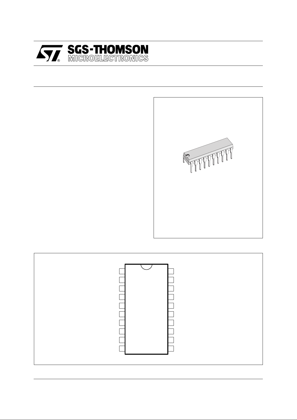
DIP20
(Plastic Package)
DESCRIP TION
The TEA2130 is a complete (horizontal and vertical) deflection processor, for TV applications and
all applications which require a flexible, high performance scanning processor (Satellite Decoder,
Video Multimedia).
PIN CONNECTIONS
REFERENCE VOLTAGE
VCR DETECTOR OUTPUT
Φ1 FILTER
GROUND
V
FRAME SAFETY INPUT
IDENTIFICATION OUTPUT
LINE SAW-TOOTH
CURRENT REFERENCE
LINE MONOSTABLE CAPACITOR
CC
1
2
3
4
5
6
7
8
9
10
20
19
18
17
16
15
14
13
12
11
ORDER CODE : TEA2130
NOISE MEASUREMENT OUTPUT
VIDEO INPUT
50% CAPACITOR
VCO INPUT
FRAME SAW-TOOTH GENERATOR
FRAME SAW-TOOTH OUTPUT
2 FILTER
Φ
LINE FLYBACK INPUT
SUPER SANDCASTLE OUTPUT
LINE OUTPUT
September 1993
2130-01.EPS
1/8
Page 2
TEA2130
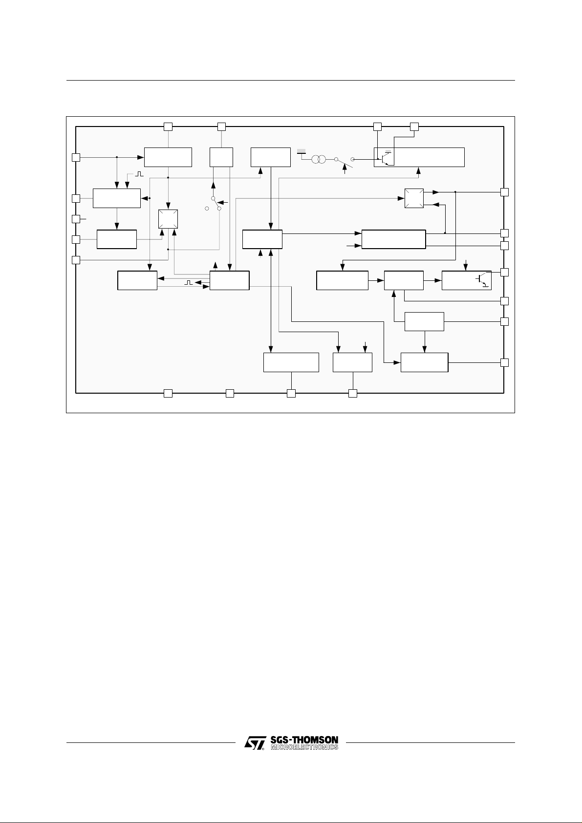
BLOCK DIAGRAM
19
20
1
2
3
NOISE
MEASURMENT
V /2
CC
AUTO VCR
SWIT CH
2µs
DIGITAL MU T
LINE SYNCHRO
SEPARATOR
LS
Φ
1
2µs
Mute
GND
V
REF
500kHz
Burst
ϕ1
1718
VCO
500kHz
Mute
LINE LOGIC
V
CC
ϕ2
FRAME
SEPARATOR
FRAME
LOGIC
Mute
FRAME SECURITY
DETECTION
50/60Hz
6754
Ident 60Hz
Burst
PHASE CONTR O L
LINE OUTPUT
50/60Hz &
MUT OUTPUT
FRAME SAWTOOTH
SUPER SAND
CASTL E G ENERATO R
LINE
MONOST
1.3V
REFERENCE
Mute
RAZ
LINE SAWTOOTH
GENERATOR
1516
GENERATOR
RAZ
Φ
2
VOLTAGE
Inhibition
LINE
OUTPUT
1.3V
14
13
12
11
10
9
8
2130-02.EPS
GENERAL DES CRI PTI O N
Introd uction
This integrated c ircuit us es high dens ity I2L bipolar
technology and combines analog signal processing with digital processing.
Timing signals are obtained from a voltage-c ontrolled oscillator (VCO) operating at 500kHz by means
of a cheap ceramic resonator. This avoid the frequency adjustment normally required with line and
frame oscillators.
A chain of dividers and appropriate logic circuitry
produces very accurate defined sampling pulses
and the necessary timing signals.
Internal Functi o ns
- Horizontal scanning processor
- Frame scanning proc essor
- B class frame output stage using an external
power amplifier with flyback generator
- Line and frame synchronization separation
- Dual phase-locked loop horizontal scanning
- High performance frame and line sync hronization
with interlacing control.
- Supersandcastle generator with reduced burst
gate pulse for 60Hz
- Automatic 50Hz / 60Hz standard identification
- Frame saw-tooth generator
- Digital video identification circuit
- Very steady free running mode of the line and
frame oscillator when no video is detected. This
allows on screen display without phase Jitter in
research mode of the tuner
- Automatic VCR mode recognition for time constant switching
- Frame safety input
WORKING DES CRI PT IO N
Synchronization Separator
Line synchronization separator is clamped to black
level of input video signal with synchronization
pulse bottom level measurement.
The synchronization pulses are divided centrally
between the black level and the synchronization
pulse bottom level, to improve performance on
video signal in noise conditions.
2/8
Page 3

TEA2130
Frame Synchronizatio n
Frame synchroniz ation is fully integrate d (no external capacitor required).
The frame timing identification logic permits automatic adaptation to 50-60Hz standards or non-interlaced video.
An automatic synchronization window width system provides:
- Fast frame capture (7.3ms wide window)
- Good noise immunity (0.4ms narrow window)
The internal generator starts the discharge of the
sawtooth generator capacitor, so that it is not disturbed by line flyback effects .
Thanks to the logic control, the beginning of the
charge phase does not depend on any disturbing
effect of the line flyback . A 32µs timing is automatically applied on standardized transmissions for
perfect interlacing.
In VCR mode, the discharge time is controlled by
an internal monostable independent of the line
frequency and gives a direct frame synchronization.
Horizontal Scanning
The horizontal scanning frequency is obtained from
the 500kHz VCO.
The circuit uses two PL L:
- The first one controls the frequency
- The second one controls the relative phase of the
output line pulse and the line flyback signals.
The output pulse has a constant duration of 29µs,
independent of V
and of any delay in switching-
CC
off the scanning transistor.
Supersandcastle Generator
This output delivers a 3 level synchronization signal:
- Burst level
- Line blanking level
- Frame blanking level
In the event of vertical scanning failure, the frame
blanking level goes high to protect the tube.
Frame Scanning
The current to charge the frame sawtooth generator is automatically switched to 60Hz operation t o
maintain constant amplitude.
Automatic VCR Mode Recog n ition for Tim e
Constant Switching
- A third phase comparator is used to detect VCR
signals and to switch the φ1 short time constant.
- A noise level measurement is realized on the
video synchronization pulse to inhibit the short
time constant if the noise level is superior to an
adjustable threshold.
- VCR signals are detected if peak to peak signal
on pin 2 is superior to an internal threshold.
This threshold is depending on the noise level. So
with a no noisy video signal, the auto VCR switch
sensitivity is maximum, and it decreases when th e
noise increases.
- The sensitivity of the noise gate and the auto VCR
switch is adjustable by external resistance.
- Long and short time constants can be selected
manually by Pin 20.
Digital Video Ident ificati on
A digital circuit controls the identification signal.
When identification signal is low, the line oscillator
is set on a reference frequency . When identificat ion
signal is high, φ1 is locked and the c atch ing phase
can start. So that, the TEA2130 allowed on screen
displays in a steady way even without video signal
(during tuner research for example).
Identificati o n Ou tp ut
The identification function provides three different
levels :
- 0V : No video identification
- 6V : 60Hz video identification
- 12V : 50Hz video identification
This information may be used for timing research
in the case of frequency or voltage s ynthetizer type
receivers and for audio muting.
ABSOLUTE MAXIMUM RATINGS
Symbol Parameter Value Unit
CC
16
11
13
AMB
Supply Voltage 13.5 V
Pulse/Frame Sawtooth Generator Voltage VCC - 3 V
Output Current 40 mA
Input Current ± 5 mA
Operating Ambient Temperature 0 , + 70
V
V
I
I
T
THERMAL DATA
Symbol Parameter Value Unit
R
th(j-a)
Junction-ambient Thermal Resistance 80
o
o
C/W
C
2130-01.TBL
2130-02.TBL
3/8
Page 4

TEA2130
ELECTRICAL CHARACT E RIS TICS (T
= 25oC; VCC = 12V; Pulse duration 50% of the amplitude)
amb
Symbol Parameter Test conditions Min. Typ. Max. Unit
Supply Voltage 12 V
Supply Current Without load in pins 7-12-15 20 29 40 mA
Starting Voltage for Line Output VCC rising 7 7.5 V
V
CC
Switch-off Voltage for Line Output V
decreasing 6.5 V
CC
VIDEO INPUT (Pin 19)
Video Signal Amplitude Z source < 220Ω 0.2 1 3 V
Push out Current During the synch. pulse - 40 - 32 - 24 µA
Pull in Current During the line 3 5 7 µA
50% SYNCH. PULSE CLAMP (Pin 18)
Push out Current During the synch. pulse - 960 - 350 - 40 µA
Pull in Current During the line 15 23 32 µA
φ 1 AND φ 3 COMPARATOR (Pin 2- Pin 3)
Short Time Output Current Identification high ± 1.1 ± 1.5 ± 2mA
Long Time Output Current Identification high ± 0.30 ± 0.48 ± 0.65 mA
VCO (Pin 17)
Catching Range Ceramic CSB 503B
= 470Ω
R
SERIAL
15.40 15.92 kHz
Transfer Characteristic ∆F pin 11/∆V pin 3 2 kHz/V
Free Running Frequency Without video signal 15.6 15.9 16.2 kHz
VIDEO IDENTIFICATION AND STANDARD OUTPUT (Pin 7)
No video on Pin 19 R
/GND = 5kΩ 0 500 mV
LOAD
60Hz video 5.5 6 6.5 V
50Hz video 10.5 11.3 V
REFERENCE VOLTAGE (Pin 1)
Output voltage I
Output impedance ∆I
= 0 5.5 6 6.5 V
1
= ± 50µA 400 600 800 Ω
1
Max output current 200 µA
AUTO VCR SWITCH (Pin 2)
V Switching threshold /V
time ct2 on ϕ1 PM Active above
Short
1
Threshold
● With no noise on the video
(V20 < 6V)
● With noise on video
(6V < V
< 7.3V
20
± 0.2 ± 0.3 ± 0.4 V
0.69 x V20 - 3.85 V
NOISE GATE (Pin 20)
Measure sampling time On the synch. pulse bottom 1 2 3 µs
Max. push out current Vnoise = 0.4V
Video Signal
2V
PP
VCR mode inhibition threshold
(long time cte)
Active above threshold
Voltage hysteresis
, F = 1MHz on
PP
Measure bandwidth (-3dB) High cut frequency
Low cut frequency
Short time constant manual
Active under threshold 4.5 5 5.5 V
6.9 7.3
350 µA
7.5 V
100
2
0.7
MHz
MHz
switching threshold
PP
mV
2130-03.TBL
4/8
Page 5

TEA2130
ELECTRICAL CHARACT E RIS TICS (cont i nued)
(T
= 25oC; VCC = 12V; Pulse duration 50% of the amplitude)
amb
Symbol Parameter Test conditions Min. Typ. Max. Unit
φ 2 COMPARATOR (Pin 14)
Output current During line flyback ± 300 ± 500 ± 700 µA
Delay between φ 2 falling edge
and the middle video sync. pulse
LINE MONOSTABLE (Pin 10)
Charge current Line output high - 67 µA
Discharge current Line output low 170 µA
Flip-Flop threshold Falling edge on the line output 1.3 V
LINE OUTPUT (Pin 11)
Low level I
Pulse duration R
φ 2 adjustment range Controlled by V
LINE SAW-TOOTH (Pin 8)
Charge Current R
Discharge Current 3.5 7 mA
Discharge Duration Controlled by logic VCO 500kHz 6.5 µs
LINE FLYBACK INPUT (Pin 13)
Blanking Line Threshold Active above threshold 0.35 0.4 0.6 V
φ 2 Loop Threshold and Line
Output Inhibition (Pin 11)
Input Current - 0.4V < V
SUPER SANDCASTLE GENERATOR (Pin 12)
Burst Level R
Line Blanking Level 4 4.5 5 V
Frame Blanking Level 2 2.5 3 V
Delay between the midde of the
video sync. pulse and the rising
edge of the burst (t
)
1
= 500 kHz 2.2 2.7 3.2 µs
F
VCO
= 20 mA 1 V
11
= 3.32kΩ , C10 = 1.5nF 27 29.5 32 µs
9
compared with
video signal
= 3.32 kΩ - 200 - 180 - 150 µA
9
14
15 18 µs
Active above threshold 2.7 3 3.3 V
< 0.4V
0.4V < V13 < 3V
3V < V
= 2.2 kΩ to ground 9 V
L
13
13
- 20
- 10
-10
- 5
- 4
- 4
- 1
2.45 2.8 3.15 µs
µA
µA
µA
t
1
2130-03.EPS
Burst Pulse Duration
● 50Hz
● 60Hz
4.1
3.6
4.4
3.9
4.7
4.2
µs
µs
Line Blanking Duration Fixed by flyback
Signal pin 13
Frame Blanking Duration Fixed by the logic 21 Line
2130-04.TBL
5/8
Page 6

TEA2130
ELECTRICAL CHARACT E RIS TICS (cont i nued)
T
= 25oC; VCC = 12V; Pulse duration 50% of the amplitude
amb
Symbol Parameter Test conditions Min. Typ. Max. Unit
FRAME SAW-TOOTH GENERATOR
Low DC Voltage 1.1 1.3 1.45 V
Discharge Current 15 60 mA
60Hz Internal Current - 10 - 8 - 6 µA
FRAME LOGIC SYNCH.
Free Running Period Without video signal 315 Line
Synchronization Windows Identification low
CURRENT REFERENCE (Pin 9)
Voltage R9 = 3.32 kΩ (1%) 1.2 1.3 1.4 V
V
9
Max. Temperature Shift ∆T = 80
FRAME SAFETY INPUT (Pin 6)
Switching Threshold Actived without negative pulse
Output current - 35 - 50 - 67 µA
Identification 60Hz high
VCR mode
o
C ± 1%
during frame blanking time for
permanent frame blanking on SSC
output Pin 12
247
247
247
361
277
361
Line
Line
Line
1.3 V
2130-05.TBL
6/8
Page 7

TYPICAL TV APPLICATION
TEA2130
4.7nF
VIDEO
INPUT
BNC
10µF
VERTICAL OUT
HORIZONTAL FLYBACK INPUT
SSC OUT
Ω
10k
3.32k
Ω
10k
1%
VERTICAL FEEDBACK
Ω
HORIZONTAL OUT
47nF
2.2k
Ω
1kΩ
470kΩ
MUTE & 50/60Hz OUT
3.3nF 1.5nF
22nF
Line Flyback
10 V
PP
22k
Ω
HORIZONTAL
POSITION
V
CC
2130-04.EPS
4.7MΩ
220nF
1nF
+200V DC
2.2
Ω
2.2k
Ω
C5B503B
Ω
470
J1
100nF
220nF
75
Ω
20 19 18 17 16 15 14 13 12
TEA2130
12345
100kΩ470kΩ
4.7nF
33nF
2.2µF
2.7kΩ
3.9kΩ
67891110
100nF
1000µF
V
CC
+12V
100k
1nF
Ω
TYPICAL SYNC SEPARA T OR APPLICATION
C5B503B
470Ω
4.7nF
VIDEO
INPUT
470k
J1
BNC
Ω
10µF
100nF
220nF
75
Ω
20 19 18 17 16 15 14 13 12
TEA2130
12345
100k
Ω
4.7nF
33nF
2.2µF
3.9k
2.7k
Ω
Ω
+12V
V
CC
2.7kΩ
3.3nF
100nF
1000µF
+5V
10kΩ
6
7891110
NC
V
3.32k
1%
CC
VERTICAL OUT
Ω
LINE SYNC OUTPUT
2.2kΩ
NC
MUTE & 50/60Hz OUT
10kΩ
2130-05.EPS
7/8
Page 8

TEA2130
PACKAGE MECHANICAL DATA
20 pins - PLASTIC DIP
I
a1
L
Z
e3
b
B
e
E
Z
D
20 11
F
110
Dimensions
Min. Typ. Max. Min. Typ. Max.
a1 0.254 0.010
B 1.39 1.65 0.055 0.065
b 0.45 0.018
b1 0.25 0.010
D 25.4 1.000
E 8.5 0.335
e 2.54 0.100
e3 22.86 0.900
F 7.1 0.280
i 3.93 0.155
L 3.3 0.130
Z 1.34 0.053
Millimeters Inches
b1
PM-DIP20.EPS
DIP20.TBL
Information furnished i s believed to be accurate and rel iabl e. However, S GS-THOMSON Microel ectroni cs assumes no responsibil ity
for the consequences of use of such information nor for any infringement of patents or other rights of third parties which may result
from its use. No licence is granted by implication or otherwise under any patent or patent rights of SGS-THOMSON Microelectronics.
Specifications mentioned in this publication are subject to change without notice. This publication supersedes and replaces all
information previously supplied. SGS-THOMSON Microelectronics products are not authorized for use as critical components in life
support devices or systems without express written approval of SGS-THOMSON Microelectronics.
© 1994 SGS-THOMSON Microelec tronics - All Rights Reserved
2
Purchase of I
2
C Patent. Rights to use these components in a I2C system, is granted provided that the system conforms to
I
Australia - Brazil - China - France - Germany - Hong Kong - Italy - Japan - Korea - Malaysia - Malta - Morocco
The Netherlands - Singapore - Spain - Sweden - Switzerland - Taiwan - Thailand - United Kingdom - U.S.A.
C Components of SGS-THOMSON Microelectronics, conveys a license under the Philips
2
C Standard Specifications as defined by Philips.
the I
SGS-THOMSON Microelectronics GROUP OF COMPANIES
8/8
 Loading...