

Page 1
HORIZONTALAND VERTICALDEFLECTIONMONITOR
.
DIRECTLINE DARLINGTON DRIVE
.
DIRECTFRAME-YOKEDRIVE (± 1A)
.
COMPOSITE VIDEO SIGNAL INPUT CAPABILITY
.
FRAME OUTPUT PROTECTION AGAINST
SHORT CIRCUITS
.
PLL
.
HORIZONTAL OSCILLATOR FREQUENCY
RANGEFROM 15kHz TO 100kHz
.
VERTICAL OSCILLATOR FREQUENCY
RANGEFROM 30Hz TO 120Hz
.
VERYFEWEXTERNALCOMPONENT
.
VERYLOWCOST POWERPACKAGE
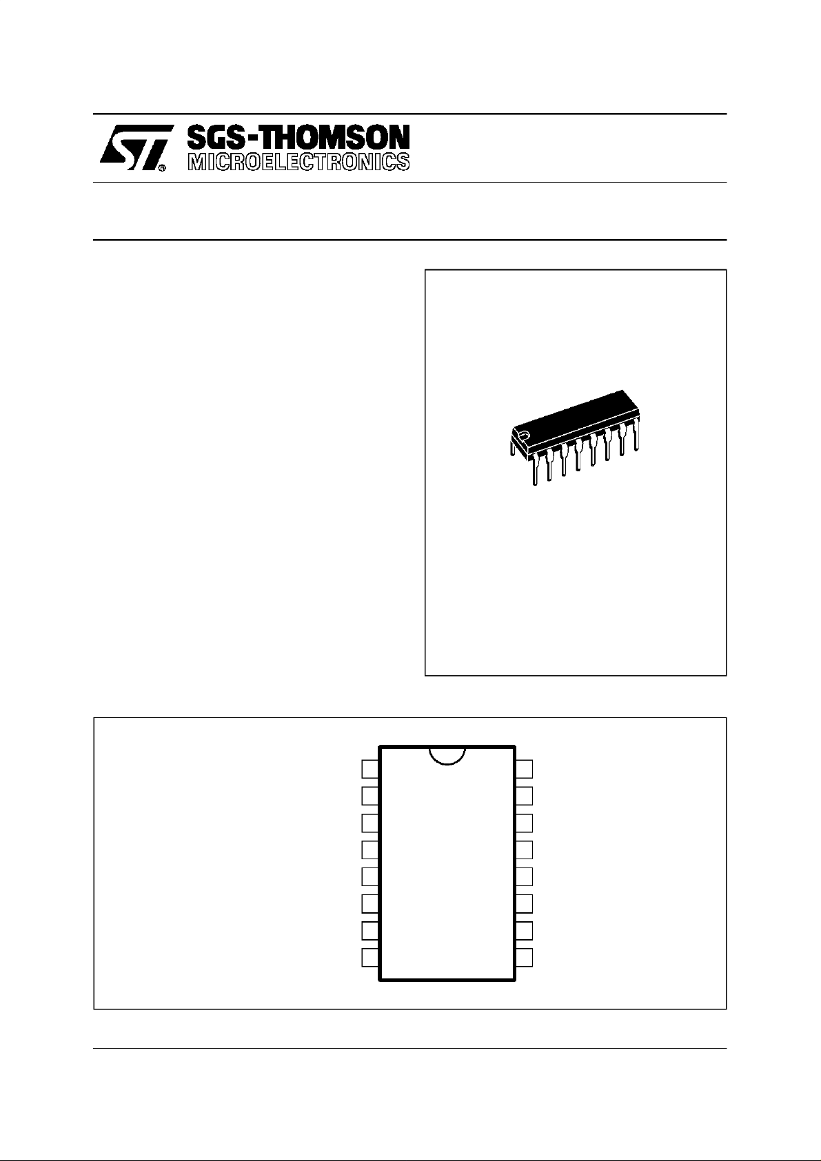
TEA2037A
POWERDIP (8+8)
(Plastic Package)
ORDER CODE : TEA2037A
DESCRIPTION
The TEA2037Aisanhorizontaland verticaldeflection circuit.It uses the same concept as TEA2117
but optimisedfor small screens,for a verylow cost
solution.
PINCONNECTIONS
FRAME OSCILLATOR
FLYBACK GENERATORSUPPLY
FRAMEFLYBACK
GROUND
GROUND
INVERTING INPUT
FRAMEPOWER SUPPLY
FRAME OUTPUT
1
2
3
4
5
6
7
8
16
15
14
13
12
11
10
9
V
CC1
VIDEO INPUT
LINE OUTPUT
GROUND
GROUND
LINE FLYBACK
PHASEDETECTOR
LINE OSCILLATOR
September 1996
2037A-01.EPS
1/9
Page 2
TEA2037A
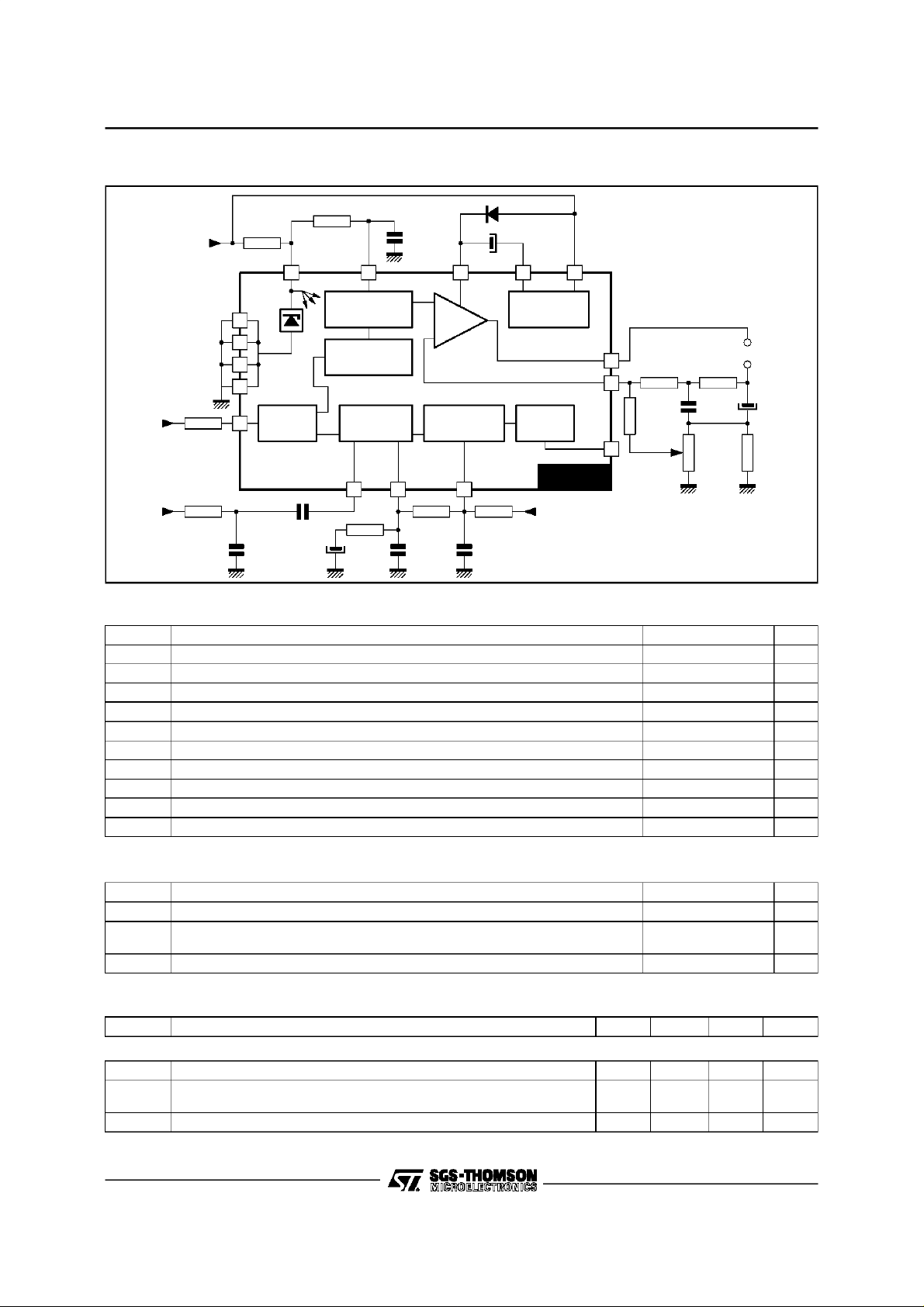
BLOCK DIAGRAM
16
4
5
12
13
INPUT
15
STAGE
123
FRAME
OSCILLATOR
FRAME
FRAME-SYNC.
OSCILLATOR
SEPARATOR
PHASE
DETECTOR
7
+
POWER
STAGE
-
LINE
OSCILLATOR
FLYBACK
GENERATOR
OUTPUT
STAGE
8
6
14
Yoke
TEA2037A
91011
V
CC1
ABSOLUTE MAXIMUM RATINGS
Symbol Parameter Value Unit
V
V
V
I
V
I
p14
I
C14
T
SupplyVoltage 30 V
CC1
Flybcak Generator SupplyVoltage 35 V
2
Frame Power Supply Voltage 60 V
7
Frame Output Current (non repetitive) ± 1.5 A
8nr
I
Frame Output Current (continuous) ± 1A
8
LineOutput Voltage(external) 60 V
14
LineOutput Peak Current 0.8 A
LineOutput Continuous Current 0.4 A
Storage Temperature -40, +150
stg
T
Max. Operating Junction Temperature +150
j
2037A-02.EPS
o
C
o
C
2037A-01.TBL
THERMALDATA
Symbol Parameter Value Unit
R
th (j-c)
R
th (j-a)
ELECTRICALCHARACTERISTICS (T
Symbol Parameter Min. Typ. Max. Unit
SUPPLY (shunt regulator) (Pin 16)
I
CC1
V
∆V
LPS Starting Threshold for Line Output Pulses 5 V
2/9
Junction-case Thermal Resistance Max. 15
Junction-ambient Thermal Resistance
(soldered on a 35µm thick 45cm
Recommended Junction Temperature Max. 120
T
j
2
PC board copper area)
=25oC)
amb
Typ. 45
SupplyCurrent 10 20 mA
SupplyVoltage (I
CC1
VoltageVariation (I
CC1
= 15mA)
CC1
: 10mA to20mA)
CC1
9
-280
9.8
50
10.5
+280VmV
o
C/W
o
C/W
o
C
2037A-02.TBL
2037A-03.TBL
Page 3
TEA2037A
ELECTRICALCHARACTERISTICS (T
=25oC) (continued)
amb
Symbol Parameter Min. Typ. Max. Unit
VIDEO INPUT (Pin 15)
V
Reference Voltage (I15=-1µA) 1.4 1.75 2 V
15
MWF Minimum Width of Frame Pulse (when synchronized with TTL Signal) 50 µs
V
Sync Bottom to Black Level (R
IN
= 560kΩ) 0.2 0.3 V
SYNC 15
LINE OSCILLATOR (Pin 9)
LT9 Low Threshold Voltage 2.8 3.2 3.6 V
HT9 High ThresholdVoltage 5.4 6.6 7.8 V
BI9 Bias Current 100 nA
DR9 Discharge Impedance 1.0 1.4 1.8 kΩ
FLP1 Free Running Line Period
(R = 34.9kΩ Tied to V
CC1
, C= 2.2nF Tied to Ground)
62 64 66 µs
FLP2 Free Running Line Period (R = 13.7kΩ, C= 2.2nF) 27 µs
OT9 Oscillator Threshold for Line OutputPulse Triggering 4.6 V
∆F
∆θ
Horizontal Frequency Driftwith Temperature (see application Fig. 8) 2 Hz/
LINE OUTPUT (Pin 14)
LV14 Saturation Voltage (I
= 200mA) 1.1 1.6 V
14
OPW Output Pulse Width (line period = 64µs) 20 22 24 µs
LINE FLYBACK INPUT (Pin11)
V
Bias Voltage 1.8 2.4 3.2 V
11
Z11 InputImpedance 4.5 5.8 8 kΩ
PHASE DETECTOR
I
Output Current during Synchro Pulse 250 450 800 µA
10
RI10 Current Ratio (positive/negative) 0.95 1 1.05
LI10 Leakage Current -2 +2 µA
CV10 ControlRange Voltage 2.60 7.10 V
FRAME OSCILLATOR (PIn 1)
LT1 Low Threshold Voltage 1.6 2.0 2.3 V
HT1 High ThresholdVoltage 2.6 3.1 3.6 V
BI1 Bias Current 30 nA
DR1 Discharge Impedance 300 470 700 kΩ
FFP1 Free Running Line Period
(R = 845kΩ Tied to V
CC1
MFP Minimum Frame Period (I
, C = 180nF Tiedto Ground)
= -100µA) (with the same RC) 12.8 ms
15
20.5 23 25 ms
FFP2 Free Running Line Period (R = 408kΩ, C = 220nF) 14.3 ms
FPR Frame PeriodRatio = 1.7 1.8 1.9
FG Frame Saw-tooth Gain between Pin 1 and non-inverting Input of the
-0.4
Frame Amplifier
∆F
∆θ
Vertical Frequency Driftwith Temperature (see application Fig. 8) 4 ⋅ 10
-3
FRAME POWER SUPPLY (Pin 7)
V
Operating Voltage (with flyback generator) 10 58 V
7
I
SupplyCurrent (V7= 30V) 22 mA
7
FLYBACK GENERATOR SUPPLY (PIn 2)
V
Operating Voltage 10 30 V
2
PP
o
Hz/oC
C
2037A-04.TBL
3/9
Page 4

TEA2037A
ELECTRICALCHARACTERISTICS (T
=25oC) (continued)
amb
Symbol Parameter Min. Typ. Max. Unit
FRAME OUTPUT (PIn 8)
LV8A
LV8B
HV8A
HV8B
FV8A
FV8B
Saturation Voltage to Ground (V
= 0.1
I
8
=1A
I
8
Saturation Voltage toV
= -0.1
I
8
= -1A
I
8
7(V7
Saturation Voltage to V7 in Flyback Mode (V
= 0.1
I
8
=1A
I
8
7
= 30V)
= 30V)
8>V7
0.0.6
0.37
1.3
1.7
0.6
1
1.6
2.4
)
1.6
2.5
2.1
4.5
FLYBACK GENERATOR (Pins 2 and 3)
F2DA
F2DB
FSVA
FSVB
Flyback Transistor on (output = high state) (V
V3/2 with I
V2/3 with I
Flyback Transistor off (output = V
3 → 2
I
3 → 2
3 → 2
I
3 → 2
= 0.1A
=1A
= 0.1
=1A
- 8V) (V7=V2= 30V)
7
= 30V)
2
1.5
3.0
0.8
2.2
2.1
4.5
1.1
4.5
FCI Leakage Current Pin 2 170 µA
The TEA2037Aperforms all the video and power
functionsrequired to providesignals for the direct
driveof theline darlingtonand frame yoke.
It contains:
- A shuntregulator
- A synchronizationseparator
- An integrated frame separator without external
components
- A saw-toothgeneratorfor the frame
- A power amplifier for direct drive of frame yoke
(short circuitprotected)
- Anopenc ollectoroutputfor the linedarli ngt ondriv e
- A linephasedetectoranda voltagecontro losc illator
Theslice level ofsync-separationisfixedby value
of the externalresistors R
and R2.VRis an inter-
1
nallyfixed voltage.
Thesync-pulseallowsthe discharge of thecapaci-
tor by a 2x 1 current. Aline sync-pulseis notable
todischargethecapacitorunderV
/2. Aframesync
Z
pulse permits the complete discharge of the capacitor,so during theframesync-pulseQ3 andQ4
providecurrent for the other parts of thecircuit.
Figure2 : Frame Separator
V
Z
V
V
V
V
V
V
V
V
V
V
2037A-05.TBL
Figure1 : SynchronizationSeparator Circuit
SL1 SL2
V
R
15
R1
Video
R2
4/9
Q3
I
ST1 ST2
/2
V
Z
3I
SL1
The oscillator thresholds are internally fixed by
resistors. The discharge of the capacitor depends
on the internal resistor R4. The control voltage is
appliedon resistorR5.
2037A-03.EPS
Q4
2037A-04.EPS
Page 5

Figure3 : Line Oscillator
TEA2037A
V
CC1
Phase
R5
Comparator
Output
Figure4 : Phase Comparator
Line
Flyback
9
R4
2037A-05.EPS
currentfor the otherpart.Whenthelineflybackand
thevideosignal are synchronized,theoutputofthe
comparatorisanalternativelynegativeandpositive
current.The framesync-pulseinhibits the comparator to prevent frequency drift of the line oscillator
on the framebeginning.
Figure5
Integrated
Flyback
Sync Pulse
Output
Current
V
C
The sync-pulse drives the currentin the comparator. The line flyback integrated by the external
networkgiveson pin 11a saw tooth, theDC offset
of this saw tooth is fixed by VC. The comparator
outputprovidesapositivecurrentforthe part of the
signalon pin 11 greater thanto VC and anegative
2037A-06.EPS
ST1
10
ST2
V
CC1
11
V
C
2037A-07.EPS
5/9
Page 6

TEA2037A
Line Output (pin 14)
It isan open collectoroutput which is able to drive
pulse current of 800mA for a rapid discharging of
the darlingtonbase. The outputpulse time is22µs
for a 64µs period.
The oscillator thresholds are internally fixed by
resistors. Theoscillator is synchronizedduringthe
Figure6 : Frame Oscillator
INPUT CURRENT
COMPENSATION
1
last half free run period. The input current during
the chargeof the capacitorisless than100nA.
Frame Output Amplifier
This amplifier is able to drive directly the frame
yoke. Its output is short circuit and overload protected ;it containsalsoa thermalprotection.
V
CC1
Frame
Sync Pulse
To Frame
Amplifier
2037A-08.EPS
6/9
Page 7

TYPICALAPPLICATION FOR DISPLAY UNITS
Figure7 : Applicationwithout flyback generator and with sync-pulse drive ;yoke : 72mH, 40Ω
TEA2037A
V
28V
CC
1kΩ
100µF
V
CC1
820kΩ
180nF
372131254161
8
6
V
CC
56kΩ
470Ω
1/2W
2.2µF
Ω
47nF
10kΩ
1µF
15
22nF15k
11
2.2nF 2.2nF
3.9kΩ
TEA2037A
10 9
100kΩ
14
10Ω
33.2kΩ
V
CC1
1N414847Ω
Figure8 : Applicationwith flyback generatorand video ;yoke : 72mH, 40Ω
470k
220nF
100nF
2.2Ω
470k
Ω
Ω
1kΩ
470µF
100Ω
6.8Ω
2037A-09.EPS
Video
V
CC
28V
100nF151.5kΩ
1kΩ
100µF
47nF
1µF
V
CC1
180nF
560kΩ
22nF15kΩ
11
2.2nF 2.2nF
3.9kΩ
820kΩ
10 9
100kΩ
TEA2037A
33.2kΩ
V
CC1
1N4003
47µF
1N4148
372131254161
2.2Ω
100nF
8
470kΩ
470kΩ
1kΩ
6
14
V
CC
470Ω
10Ω
1/2W
680pF
2.2µF
220nF
56kΩ
100Ω
1N414847Ω
470µF
6.8Ω
2037A-10.EPS
7/9
Page 8

TEA2037A
TYPICALAPPLICATION FOR HIGH FREQUENCYMONITOR
CHARACTERISTICS
• Screen: 14’’ Colour
• Framedeflectionyoke : 11mH, 7Ω,
750mA peak–to–peak
• V
=+ 14Vwith flybackgenerator
CC
• Frame flyback time : 0.6ms
• Verticalfrequency: 72Hz
• Verticalfree–runningperiod: 16ms
(adjustable)
• Horizontalfrequency: 35kHz
(adjustable)
• Line flybacktime : 5.5µs
2.2kΩ
V
14V
Line
Flyback
CC
270kΩ
100µF
Sync
47nF
10kΩ
1µF
V
CC1
Ω
470k
150nF
15
22nF15kΩ
11
6.8nF 1nF
3.9kΩ
P3
470kΩ
10 9
1000µF
TEA2037A
47kΩ
• Capturerange : ± 5µs
(@ syncpulse = 4.7µs)
• Input signal : negative TTL sync(line + frame)
• Dissipatedpower : 1.4W
(heatsinkrequired)
• Adjustments:
• Verticalamplitude
• VerticalLinearity
• Vertical frequency
• Horizontalfrequency
1N4002
47µF
1N4148
372131254161
8
Frame Yoke
11mH/7Ω
330nF
P1
47kΩ
68kΩ
100Ω
39kΩ
6
14
680pF
V
CC
22kΩ
P4
22kΩ
220Ω
10Ω
1/2W
2.2µF
18kΩ
Line
Darlington
100nF
2.2Ω
180Ω
2200µF
1Ω
8/9
1N414847
V
CC1
Ω
2037A-11.EPS
Page 9

PACKAGE MECHANICALDATA
16 PINS- PLASTICPOWERDIP
TEA2037A
Dimensions
Min. Typ. Max. Min. Typ. Max.
Millimeters Inches
a1 0.51 0.020
B 0.85 1.40 0.033 0.055
b 0.50 0.020
b1 0.38 0.50 0.015 0.020
D 20.0 0.787
E 8.80 0.346
e 2.54 0.100
e3 17.78 0.700
F 7.10 0.280
I 5.10 0.201
L 3.30 0.130
Z 1.27 0.050
Information furnished isbelieved to be accurate and reliable. However,SGS-THOMSON Microelectronics assumes no responsibility
for the consequences ofuse of such information nor forany infringement of patentsor other rights of third parties which may result
from itsuse. No licence isgranted by implicationor otherwiseunder anypatent or patent rightsof SGS-THOMSON Microelectronics.
Specifications mentioned in this publication are subject to change without notice. This publication supersedes and replaces all
information previously supplied.SGS-THOMSON Microelectronics products are not authorized for use ascritical components in life
support devices or systems without express written approval of SGS-THOMSON Microelectronics.
1996 SGS-THOMSON Microelectronics - All Rights Reserved
Purchase of I
2
I
C Patent. Rights to usethese components in aI2C system, is granted provided thatthe system conforms to
Australia - Brazil - Canada - China - France - Germany -Hong Kong- Italy- Japan -Korea - Malaysia - Malta- Morocco
The Netherlands - Singapore - Spain - Sweden - Switzerland - Taiwan - Thailand - United Kingdom - U.S.A.
2
C Components of SGS-THOMSON Microelectronics, conveys a licenseunder the Philips
2
the I
C Standard Specificationsas defined by Philips.
SGS-THOMSON Microelectronics GROUP OF COMPANIES
PM-DIP16.EPS
DIP16PW.TBL
9/9
 Loading...