

Page 1
INTEGRATED CIRCUITS
DATA SH EET
TDA10085HT
Single chip DVB-S/DSS channel
receiver
Product specification
Supersedes data of 2000 March 16
File under Integrated Circuits, IC02
2001 Aug 31
Page 2

Philips Semiconductors Product specification
Single chip DVB-S/DSS channel receiver TDA10085HT
CONTENTS
11 FEATURES
2 APPLICATIONS
3 GENERAL DESCRIPTION
4 ORDERING INFORMATION
5 BLOCK DIAGRAM
6 PINNING
7 LIMITING VALUES
8 THERMAL CHARACTERISTICS
9 CHARACTERISTICS
10 APPLICATION INFORMATION
11 PACKAGE OUTLINE
12 SOLDERING
12.1 Introduction to soldering surface mount
packages
12.2 Reflow soldering
12.3 Wave soldering
12.4 Manual soldering
12.5 Suitability of surface mount IC packages for
wave and reflow soldering methods
13 DATA SHEET STATUS
14 DEFINITIONS
15 DISCLAIMERS
16 PURCHASE OF PHILIPS I2C COMPONENTS
2001 Aug 31 2
Page 3

Philips Semiconductors Product specification
Single chip DVB-S/DSS channel receiver TDA10085HT
1 FEATURES
• DSS andDVB-S compliant single chip demodulator and
forward error correction
• Dual 6-bit Analog-to-Digital Converter (ADC) on-chip
• PLL that allows using a low-cost crystal
(typically 4 MHz)
• DiSEqC 1.X from 1 to 8 byte-long sequences with
modulated or unmodulated output
• DSS dish control
• Digital cancellation of ADC offset
• Simultaneous parallel and serial output interfaces
• Variable rate BPSK/QPSK coherent demodulator
• Modulation rate variable from 1 to 49 Mbauds
• Automatic gain control output
• Digital symbol timing recovery:
– Acquisition range up to 960 ppm
• Carrier offset cancellation upto onehalf of the sampling
frequency
• Digital carrier recovery:
– Acquisition range up to 12% of the symbol rate
• Half-Nyquist filters: roll-off = 0.35 for DVB and
0.2 for DSS
• Interpolating and anti-aliasing filters to handle variable
symbol rates
• Channel quality estimation
• Spectral inversion ambiguity resolution
• Viterbi decoder:
– Supported rates from 1/2 to 8/9
– Constraint length K = 7 with G1 = 1718 and
G2 = 133
– Viterbi output BER measurement
– Automatic code rate search within1/2,2/3 and6/7 in
DSS mode
– Automatic code rate search within1/2,2/3,3/4,5/
and7/8 in DVB-S mode
• Convolutional de-interleaver and Reed Solomon
decoder according to DVB and DSS specifications
• Automatic frame synchronization
• Selectable DVB-S descrambling
• I2C-bus interface
• 64-pin TQFP package
• CMOS technology (0.2 µm, 1.8 V to 3.3 V).
8
6
2 APPLICATIONS
• DVB-S receivers (ETS 300-421)
• DSS receivers.
3 GENERAL DESCRIPTION
The TDA10085 is a single-chip channel receiver for
satellite television reception matching both DSS and
DVB-S standards. The device contains a dual 6-bit flash
ADC, variable rate BPSK/QPSK coherent demodulator
andforward error correctionfunctions.The ADC interfaces
directly with I and Q analog baseband signals.
After analog-to-digital conversion, the TDA10085
implements a bank of cascadable filters as well as
anti-alias andhalf-Nyquist filters. An analog AGC signalis
generated using an amplitude estimation function. The
TDA10085 performs clock recovery at twice the baud rate
and achieves coherent demodulation without any
feedback to the localoscillator. Forwarderror correction is
built around two error-correcting codes: a Reed-Solomon
(outer code) and a Viterbi decoder (inner code). The
Reed-Solomon decoder corrects up to 8 erroneous bytes
among the N (204) bytes of one data packet.
A convolutional de-interleaver is located between the
Viterbi output and the Reed-Solomon decoder input. The
de-interleaver and Reed-Solomon decoder are
automatically synchronized according to a frame
synchronization algorithm that uses the sync pattern
presentin eachpacket. The TDA10085is controlled viaan
I2C-bus interface. The circuit operates at sampling
frequencies up to 100 MHz, can process variable
modulation rates and achieves transmission rates up to
45 Mbaud. Furthermore, for dish control applications,
hardware supports DiSEqc 1.x with control access via the
I2C-bus.
An interrupt line that can be programmed to activate on
events or on timing information is provided.
Designed in 20 micron CMOS technology and housed in a
TQFP64 package, the TDA10085 operates over the
commercial temperature range.
2001 Aug 31 3
Page 4
Philips Semiconductors Product specification
Single chip DVB-S/DSS channel receiver TDA10085HT
4 ORDERING INFORMATION
TYPE
NUMBER
NAME DESCRIPTION
PACKAGE
VERSION
TDA10085HT TQFP64 plastic thin quad flat package; 64 leads; body 10 × 10 × 1.0 mm SOT357-1
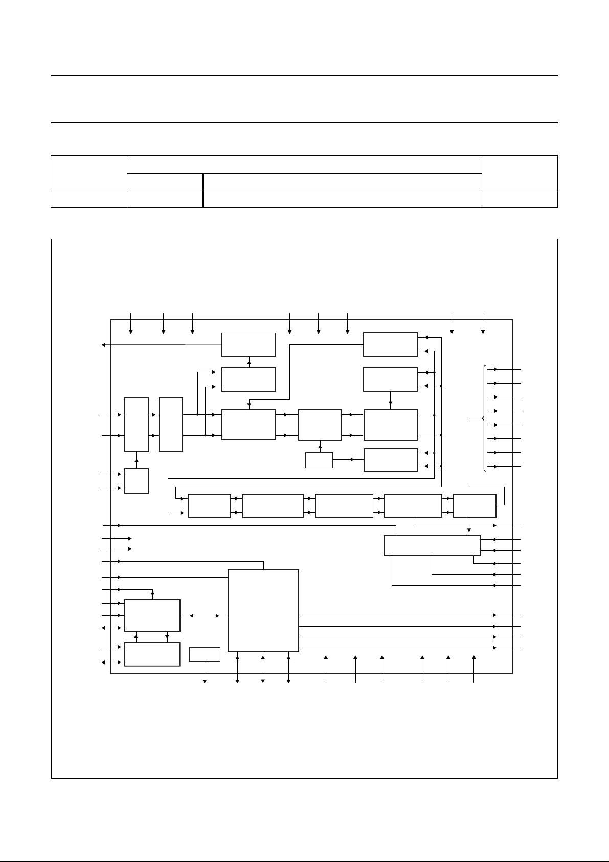
5 BLOCK DIAGRAM
handbook, full pagewidth
VAGC
VIN1
VIN2
XIN
XOUT
ENSERI
VREFN
VREFP
TMD
CLB#
SADDR0
IICDIV
SCL
SDA
SCL-0
SDA-0
VDDE57DVCC
24
30
15
ADC
12
DUAL 6-BIT
1
PLL
2
19
13
14
18
46
17
20
33
I2C-BUS
INTERFACE
32
29
I2C-BUS
28
TUNER SWITCH
VDDI
3, 8, 26,
38, 55
ADC OFFSET
CANCELLATION
VITERBI
DECODER
DISECQ
22K
PWM
ENCODER
AGC
DETECTION
COMPLEX
MULTIPLIER
DE-INTERLEAVER
PLLVCC
4
VDD3
FILTER
AVD
10
BANK
NCO
REED SOLOMON
DECODER
16
TDA10085HT
CONTROL
LOGIC
63 21 22 31 5 6
CTRL1 CTRL3 PLLGND DGDND
CTRL2
ADVD
42
CARRIER
SYNC
AGC
DETECTION
HALF-NYQUIST
FILTERS
CLOCK
SYNC
DE-SCRAMBLER
BOUNDARY SCAN
9, 25, 39,
56, 64
VSSI AVS ADVS VSSE
11
INTERFACE
43
VDDE
OUTPUT
23, 45,
58
27, 44,
57
62
DO7
61
DO6
60
DO5
59
DO4
54
DO3
53
DO2
52
DO1
51
DO0
37
FEL
34
TMS
35
TCK
36
TRST
40
TDI
41
TDO
47
PSYNC
48
UNCOR
49
DEN
50
OCLK
MGU427
Fig.1 Block diagram.
2001 Aug 31 4
Page 5
Philips Semiconductors Product specification
Single chip DVB-S/DSS channel receiver TDA10085HT
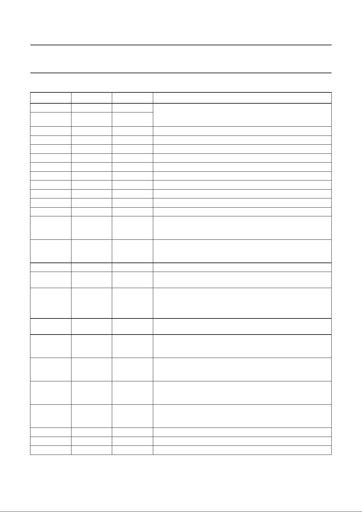
6 PINNING
SYMBOL PIN TYPE DESCRIPTION
XIN 1 I crystal oscillator input and output pins; in a typical application, a
XOUT 2 I
VDDI 3 supply digital core supply voltage (typically 1.8 V)
PLLVCC 4 supply analog supply voltage for the PLL (typically 3.3 V)
PLLGND 5 ground analog ground for the PLL
DGND 6 ground digital PLL core ground voltage; see note 2
DVCC 7 supply digital PLL core supply voltage (typically 1.8 V)
VDDI 8 supply digital ADC supply voltage (typically 1.8 V)
VSSI 9 ground digital ADC ground voltage; see note 2
VDD3 10 supply analog ADC supply voltage (typically 3.3 V)
AVS 11 ground analog ground voltage
VIN2 12 I analog signal input for channel Q; see note 1
VREFN 13 O negative analog voltage reference output (typically 1.25 V); a
VREFP 14 O positive analog voltage reference output (typically 2 V); a decoupling
VIN1 15 I analog signal input for channel I; see note 1
AVD 16 supply analog supply voltage (typically 3.3 V); a 0.1 µF decoupling capacitor
SADDR0 17 I SADDR0 input signal is the LSB of the I
TMD 18 I test input; must be connected to ground for normal operation; see
ENSERI 19 I enable serial interface input; when HIGH, the serial transport stream
IICDIV 20 I input to select the I
CTRL1 21 OD control line output 1; this pin function is directly programmable
CTRL2 22 OD control line output 2; this pin function is directly programmable
VSSE 23 ground digital ground voltage; see note 2
VDDE5 24 supply digital 5 V supply voltage; required for the 5 V tolerance of inputs
VSSI 25 ground digital core ground voltage; see note 2
fundamental oscillator crystal is connected between pins XIN and
XOUT; see note 1
decoupling capacitor (typically 0.1 µF) must be placed as close as
possible between VREFN and GND
capacitor (typically 0.1 µF) must be placed as closed as possible
between VREFP and GND
must be placed between AVD and AVS
2
C-bus address of the
TDA10085; other bits of the address are set internally to 000111,
therefore the complete I2C-bus address is (MSB to LSB):
0, 0, 0, 1, 1, 1 plus the SADDR0 bit; see note 1
note 1
is present on the boundary scan pins (TRST, TDO, TCK, TDI
and TMS); when LOW, the boundary scan pins are available; note 1
2
C-bus internal system clock frequency (depends
on the crystal frequency); internal I2C-bus clock is XIN when
IICDIV = 0 and XIN/4 if IICDIV = 1; see note 1
through the I
2
C-bus interface; default value is logic 1; open-drain
output requiring an external pull-up resistor to 3.3 V or to 5 V
through the I
2
C-bus interface; default value is logic 1; open-drain
output requiring an external pull-up resistor to 3.3 V or to 5 V
2001 Aug 31 5
Page 6

Philips Semiconductors Product specification
Single chip DVB-S/DSS channel receiver TDA10085HT
SYMBOL PIN TYPE DESCRIPTION
VDDI 26 supply digital core supply voltage (typically 1.8 V)
VDDE 27 supply digital supply voltage (typically 3.3 V)
SDA_0 28 I/OD I
SCL_0 29 OD I
VAGC 30 O or OD PWM encoded output signal for AGC; the refresh frequency of AGC
CTRL3 31 I/OD control line 3 input/open drain output; this pin function is directly
SDA 32 I/OD I
SCL 33 I I
TMS 34 I/O boundary scan mode: test mode select input/output; provides the
TCK 35 I/O boundary scan mode: test clock input/output; TCK is an independant
TRST 36 I/O boundary scan mode: testreset input/output; TRSTis an active-LOW
FEL 37 OD front-end locked output signal that goes HIGH when demodulator,
VDDI 38 supply digital core supply voltage (typically 1.8 V)
VSSI 39 ground digital core ground voltage; see note 2
TDI 40 I/O boundary scan mode: test data and instruction serial input
2
C-bus bidirectional serial input/ open drain output; equivalent to
SDA but with a high-impedance state programmable via the I2C-bus;
a pull-up resistor must be connected between this pin and DVCC
2
C-bus clock output; equivalent to SCL but with a high-impedance
state programmable via the I2C-bus; open drain output requiring an
external pull-up resistor to 5 V
information isthe sampling frequency divided by 2048, the maximum
1
signal frequency on the VAGC output is
/4× AGC sampling clock;
the VAGC output can be selected by I2C-bus to be open-drain or
have 3.3 V capability (typically, output VAGC is fed to the AGC
amplifier through a single RC network)
programmable through the I
2
C-bus interface and is an input by
default; it requires a pull-up resistor to 3.3 or 5 V, or a pull-down
resistor to GND
2
C-bus bidirectional serial data input/output; the open-drain output
requires apull-up resistor (typically 2.2 kΩ) to be connected between
SDA and 5 V for proper operation
2
C-bus clock input; nominally a square wave with a maximum
frequency of 400 kHz generated by the system I2C-bus master; see
note 1
logic levels needed to change the TAP controller from state to state
serial mode enabled (ENSERI = 1): serial TS uncorrectable output;
when not in serial mode, TMS must be set to VSS
clock used to drive the TAP controller
serial mode enabled (ENSERI = 1): TCK is the serial TS clock
output; when not in serial mode, TCK must be set to VSS
reset input to the TAP controller
serial mode enabled (ENSERI = 1): test reset input/output; TRST is
the serial TS PSYNC output; when notin serial mode, TRST must be
set to VSS
Viterbi decoder and de-interleaver are all synchronized; open-drain
output requiring an external pull-up resistor to 3.3 or 5 V; can be set
via the I
2
C-bus to be an interrupt pin
serial mode enabled (ENSERI = 1): serial TS data output; must be
set to VSS when not in serial mode
2001 Aug 31 6
Page 7

Philips Semiconductors Product specification
Single chip DVB-S/DSS channel receiver TDA10085HT
SYMBOL PIN TYPE DESCRIPTION
TDO 41 I/O boundary scan mode: test data serial output; output provided on the
falling edge of TCK
serial mode enabled (ENSERI = 1): serial TS enable input; must be
set to VSS when not in serial mode
ADVD 42 supply analog supply voltage for the 2nd PLL (typically 1.8 V)
ADVS 43 ground analog ground voltage for the 2nd PLL
VDDE 44 supply digital supply voltage (typically 3.3 V)
VSSE 45 ground digital ground voltage; see note 2
CLB# 46 I asynchronous, active LOW input that clears the TDA10085; when
CLB# goes LOWthe circuit immediately enters its RESET mode and
normal operation resumes three XIN rising edges later after CLB#
returns HIGH; at RESET, the I
initialized to their default values; the minimum width of CLB# LOW
level is three XIN clock periods; pin CLB# is not TTL, 5 V tolerant
PSYNC 47 O packet sync output signal goes HIGH on a rising edge of OCLK each
time the first byte of a packet is provided
UNCOR 48 O uncorrectable packet output signal goes HIGH on a rising edge of
OCLK when the packet provided is uncorrectable
DEN 49 O data enable; this output signal is HIGH when there is valid data on
bus DO[7:0]
OCLK 50 O output clock for the parallel DO[7:0] outputs; OCLK is generated
internally and depends on which interface type is selected
DO0 51 O transport stream data output bits; part of the 8-bit parallel data output
DO1 52 O
DO2 53 O
after demodulation, Viterbi decoding, de-interleaving, RS decoding
and de-scrambling; possible output interfaces are three parallel and
two serial
DO3 54 O
VDDI 55 supply digital core supply voltage (typically 1.8 V)
VSSI 56 ground digital core ground voltage; see note 2
VDDE 57 supply digital supply voltage (typically 3.3 V)
VSSE 58 ground digital ground voltage; see note 2
DO4 59 O transport stream data output bits; part of the 8-bit parallel data output
DO5 60 O
DO6 61 O
after demodulation, Viterbi decoding, de-interleaving, RS decoding
and de-scrambling; possible output interfaces are three parallel and
two serial
DO7 62 O
22K 63 O 22 kHz output used to control the antenna LNB (output is controlled
2
via the I
C-bus interface)
VSSI 64 ground digital core ground voltage; see note 2
2
C-bus register contents are all
Notes
1. TTL, 5 V tolerant input (if VDDE5 is connected to 5 V).
2. DGND, VSSI and VSSE can be connected to the same ground plane.
2001 Aug 31 7
Page 8

Philips Semiconductors Product specification
Single chip DVB-S/DSS channel receiver TDA10085HT
handbook, full pagewidth
VSSI
22K
DO7
DO6
DO5
DO4
VSSE
VDDE
VSSI
VDDI
DO3
DO2
DO1
DO0
OCLK
DEN
64
63
62
61
60
59
58
57
56
55
54
53
52
51
50
49
XIN
XOUT
VDDI
PLLVCC
PLLGND
DGND
DVCC
VDDI
VSSI
VDD3
AVS
VIN2
VREFN
VREFP
VIN1
AVD
1
2
3
4
5
6
7
8
9
10
11
12
13
14
15
16
17
18
19
20
TMD
SADDR0
IICDIV
ENSERI
21
CTRL1
TDA10085HT
22
23
VSSE
CTRL2
24
25
VSSI
VDDE5
26
VDDI
27
VDDE
28
SDA_0
29
SCL_0
30
VAGC
31
CTRL3
32
SDA
48
47
46
45
44
43
42
41
40
39
38
37
36
35
34
33
MGU426
UNCOR
PSYNC
CLB#
VSSE
VDDE
ADVS
ADVD
TDO
TDI
VSSI
VDDI
FEL
TRST
TCK
TMS
SCL
Fig.2 Pin configuration.
2001 Aug 31 8
Page 9

Philips Semiconductors Product specification
Single chip DVB-S/DSS channel receiver TDA10085HT
7 LIMITING VALUES
In accordance with the Absolute Maximum Rating System (IEC 60134); note 1
SYMBOL PARAMETER MIN. MAX. UNIT
V
VDDE
V
VDDI
V
I
T
amb
T
j
T
sp
Note
1. Stresses abovethe Absolute MaximumRatings may causepermanent damage tothe device. Exposureto Absolute
Maximum Ratings conditions for extended periods may affect device reliability.
8 THERMAL CHARACTERISTICS
DC supply voltage −0.5 +4.1 V
DC core supply voltage −0.5 +2.2 V
DC input voltage −0.5 V
VDDE
+ 0.5 V
ambient temperature 0 70 °C
junction temperature − 150 °C
solder point temperature − 300 °C
SYMBOL PARAMETER CONDITIONS VALUE UNIT
R
th(j-a)
thermal resistance from junction to ambient in free air 45 K/W
9 CHARACTERISTICS
SYMBOL PARAMETER CONDITIONS MIN. TYP. MAX. UNIT
V
VDDE
V
VDDI
V
VDDE5
V
IH
V
IL
V
OH
V
OL
I
VDDE
I
VDDI
digital supply voltage 3.0 3.3 3.6 V
digital core supply voltage 1.6 1.8 2.0 V
digital 5 V supply voltage for 5 V tolerance of inputs 4.5 5.0 5.5 V
HIGH-level input voltage TTL input; note 1 2.0 − V
VDDE
+ 0.3 V
LOW-level input voltage TTL input −0.5 − +0.8 V
HIGH-level output voltage IOH= −0.8 mA V
I
OH
= −I
; note 4 2.4 −−V
O(max)
− 0.1 −−V
VDDE
LOW-level output voltage IOL= 0.8 mA −−0.1 V
supply current for V
supply current for V
VDDE
VDDI
I
OL=IO(max)
fs= 96 MHz 68 − 78 mA
symbol rate
; note 4 −−0.4 V
1 Mbaud − 38 − mA
27.5 Mbauds − 93 − mA
45 Mbauds −−139 mA
C
i
input capacitance − 10 − pF
XIN
f
V
V
XIN
IH
IL
crystal frequency − 4 − MHz
HIGH-level input voltage 0.7V
VDDE
LOW-level input voltage 0 − 0.3V
− V
VDDE
VDDE
V
V
PLL
V
DVCC
digital PLL supply voltage 1.6 1.8 2.0 V
2001 Aug 31 9
Page 10

Philips Semiconductors Product specification
Single chip DVB-S/DSS channel receiver TDA10085HT
SYMBOL PARAMETER CONDITIONS MIN. TYP. MAX. UNIT
V
PLLVCC
ADC
V
VDD3
V
AVD
V
VIN1
V
VIN2
C
i
V
VREFP
V
VREFN
SINAD ADC signal to noise and
THD total harmonic distortion note 3 − 35 − dB
analog PLL supply voltage 3.0 3.3 3.6 V
3 V ADC digital supply
3.0 3.3 3.6 V
voltage
analog supply voltage 3.0 3.3 3.6 V
,
analog input voltage
DC component V
VREFN
− V
AC component − 750 − mV
analog input capacitance −−16 pF
top voltage reference − 2.475 − V
bottom voltage reference − 1.725 − V
note 2 − 34 − dB
distortion ratio
VREFP
V
Notes
1. All inputs except pin CLB# are 5 V tolerant.
2. Signal-to-noise plus distortion ratio (SINAD): ratio between the RMS magnitude of the fundamental input frequency
to the RMS magnitude of all other ADC output signals.
3. Total Harmonic Distortion (THD): ratio of the RMS sum of all harmonics of the input signal (below one half of the
sampling frequency) to the RMS value at the fundamental frequency.
4. I
I
I
= 8 mA for pins OCLK and TCK
O(max)
= 4 mA for pins DO[7:0], DEN, PSYNC, UNCOR, TDI, TDO, TRST, TMS, SDA, SCL_O and SDA_O
O(max)
= 2 mA for pins CTRL1, CTRL2, CTRL3, VAGC and FEL, 22K.
O(max)
2001 Aug 31 10
Page 11

Philips Semiconductors Product specification
Single chip DVB-S/DSS channel receiver TDA10085HT
10 APPLICATION INFORMATION
handbook, full pagewidth
VAGC
MIXER
×
VIN1
30
15
XIN XOUT
21
51-54
59-62
8
DO[7-0]
from
LNB
90° PHASE
SHIFT
LO
PLL
×
MIXER
The TDA10085 can receive a 4 MHz clock signal delivered by the PLL synthesizer, or can generate the sampling clock from a crystal connected
between XIN and XOUT.
Bypass capacitors (0.1 µF) should be placed close to ADC voltage references VREFP and VREFN.
GND
VREFP
VREFN
VIN2
14
TDA10085HT
13
12
28 29 3332
SDA-0 SCL-0 SCL
SDA
50
49
48
47
OCLK
DEN
UNCOR
PSYNC
MGU428
Fig.3 Front-end receiver schematic.
handbook, full pagewidth
LNB SUPPLY
GENERATION
VAGC
30
VIN1
15
VIN2
12
28 29 3332
SDA-0 SCL-0 SCLSDA
LNB
channel I
TUNER
channel Q
Fig.4 Typical use of CTRL1 and 22K outputs.
2001 Aug 31 11
CTRL1 22K
TDA10085
6321
51-54
59-62
MPEG2
8
transport
stream
DO[7-0]
MGU429
Page 12

Philips Semiconductors Product specification
Single chip DVB-S/DSS channel receiver TDA10085HT
11 PACKAGE OUTLINE
TQFP64: plastic thin quad flat package; 64 leads; body 10 x 10 x 1.0 mm
c
y
X
A
48 33
49
Z
32
E
SOT357-1
e
w M
pin 1 index
64
1
e
w M
b
p
16
Z
D
D
H
D
b
p
17
v M
B
v M
B
0 2.5 5 mm
scale
DIMENSIONS (mm are the original dimensions)
UNIT
mm
A
A1A2A3b
max.
0.15
1.2
0.05
1.05
0.95
0.25
cE
p
0.27
0.18
0.17
0.12
(1)
(1) (1)(1)
D
10.1
9.9
eH
H
D
10.1
9.9
0.5
12.15
11.85
Note
1. Plastic or metal protrusions of 0.25 mm maximum per side are not included.
E
A
12.15
11.85
H
E
E
A
2
A
A
1
LL
p
0.75
0.45
0.08 0.11.0 0.2
detail X
Z
1.45
1.05
D
(A )
3
L
p
L
Zywv θ
E
1.45
1.05
o
7
o
0
θ
OUTLINE
VERSION
IEC JEDEC EIAJ
REFERENCES
SOT357-1 137E10 MS-026
2001 Aug 31 12
EUROPEAN
PROJECTION
ISSUE DATE
99-12-27
00-01-19
Page 13

Philips Semiconductors Product specification
Single chip DVB-S/DSS channel receiver TDA10085HT
12 SOLDERING
12.1 Introduction to soldering surface mount packages
Thistext gives averybrief insighttoa complex technology.
A more in-depth account of soldering ICs can be found in
our
“Data Handbook IC26; Integrated Circuit Packages”
(document order number 9398 652 90011).
There is no soldering method that is ideal for all surface
mount IC packages. Wave soldering can still be used for
certainsurface mount ICs,butit is notsuitablefor fine pitch
SMDs. In these situations reflow soldering is
recommended.
12.2 Reflow soldering
Reflow soldering requires solder paste (a suspension of
fine solder particles, flux and binding agent) to be applied
tothe printed-circuitboardby screenprinting,stencilling or
pressure-syringe dispensing before package placement.
Several methods exist for reflowing; for example,
convection or convection/infrared heating in a conveyor
type oven. Throughput times (preheating, soldering and
cooling) vary between 100 and 200 seconds depending
on heating method.
Typical reflow peak temperatures range from
215 to 250 °C. The top-surface temperature of the
packages should preferable be kept below 220 °C for
thick/large packages, and below 235 °C for small/thin
packages.
12.3 Wave soldering
Conventional single wave soldering is not recommended
forsurface mount devices(SMDs)or printed-circuit boards
with a high component density, as solder bridging and
non-wetting can present major problems.
To overcome these problems the double-wave soldering
method was specifically developed.
If wave soldering is used the following conditions must be
observed for optimal results:
• Use a double-wave soldering method comprising a
turbulent wavewith high upwardpressure followed bya
smooth laminar wave.
• For packages with leads on two sides and a pitch (e):
– larger than or equal to 1.27 mm, the footprint
longitudinal axis is preferred to be parallel to the
transport direction of the printed-circuit board;
– smaller than 1.27 mm, the footprint longitudinal axis
must be parallel to the transport direction of the
printed-circuit board.
The footprint must incorporate solder thieves at the
downstream end.
• Forpackages with leadsonfour sides, thefootprintmust
be placedat a 45° angle to the transport direction of the
printed-circuit board. The footprint must incorporate
solder thieves downstream and at the side corners.
During placement and before soldering, the package must
be fixed with a droplet of adhesive. The adhesive can be
applied by screen printing, pin transfer or syringe
dispensing. The package can be soldered after the
adhesive is cured.
Typical dwell time is 4 seconds at 250 °C.
A mildly-activated flux will eliminate the need for removal
of corrosive residues in most applications.
12.4 Manual soldering
Fix the component by first soldering two
diagonally-opposite end leads. Use a low voltage (24 V or
less) soldering iron applied to the flat part of the lead.
Contact time must be limited to 10 seconds at up to
300 °C.
When using a dedicated tool, all other leads can be
soldered in one operation within 2 to 5 seconds between
270 and 320 °C.
2001 Aug 31 13
Page 14

Philips Semiconductors Product specification
Single chip DVB-S/DSS channel receiver TDA10085HT
12.5 Suitability of surface mount IC packages for wave and reflow soldering methods
PACKAGE
WAVE REFLOW
(1)
BGA, HBGA, LFBGA, SQFP, TFBGA not suitable suitable
SOLDERING METHOD
HBCC, HLQFP, HSQFP, HSOP, HTQFP, HTSSOP, HVQFN, SMS not suitable
(3)
PLCC
, SO, SOJ suitable suitable
LQFP, QFP, TQFP not recommended
SSOP, TSSOP, VSO not recommended
(2)
(3)(4)
(5)
suitable
suitable
suitable
Notes
1. All surface mount (SMD) packages are moisture sensitive. Depending upon the moisture content, the maximum
temperature (with respect to time) and body size of the package, there is a risk that internal or external package
cracks may occur due to vaporization of the moisture in them (the so called popcorn effect). For details, refer to the
Drypack information in the
“Data Handbook IC26; Integrated Circuit Packages; Section: Packing Methods”
.
2. These packages are not suitable for wave soldering as a solder joint between the printed-circuit board and heatsink
(at bottom version) can not be achieved, and as solder may stick to the heatsink (on top version).
3. If wave soldering is considered, then the package must be placed at a 45° angle to the solder wave direction.
The package footprint must incorporate solder thieves downstream and at the side corners.
4. Wave soldering is only suitable for LQFP, TQFP and QFP packages with a pitch (e) equal to or larger than 0.8 mm;
it is definitely not suitable for packages with a pitch (e) equal to or smaller than 0.65 mm.
5. Wave soldering is onlysuitable for SSOP and TSSOPpackages with a pitch (e)equal toor larger than 0.65 mm; it is
definitely not suitable for packages with a pitch (e) equal to or smaller than 0.5 mm.
13 DATA SHEET STATUS
PRODUCT
DATA SHEET STATUS
(1)
STATUS
(2)
DEFINITIONS
Objective specification Development This data sheet contains data from the objective specification for product
development. Philips Semiconductors reserves the right to change the
specification in any manner without notice.
Preliminary specification Qualification This data sheet contains data from the preliminary specification.
Supplementary data will be published at a later date. Philips
Semiconductors reserves the right to change the specification without
notice, in order to improve the design and supply the best possible
product.
Product specification Production This data sheet contains data from the product specification. Philips
Semiconductors reserves the right to make changes at any time in order
to improve the design, manufacturing and supply. Changes will be
communicated according to the Customer Product/Process Change
Notification (CPCN) procedure SNW-SQ-650A.
Notes
1. Please consult the most recently issued data sheet before initiating or completing a design.
2. The product status of the device(s) described in this data sheet may have changed since this data sheet was
published. The latest information is available on the Internet at URL http://www.semiconductors.philips.com.
2001 Aug 31 14
Page 15

Philips Semiconductors Product specification
Single chip DVB-S/DSS channel receiver TDA10085HT
14 DEFINITIONS Short-form specification The data in a short-form
specification is extracted from a full data sheet with the
same type number and title. For detailed information see
the relevant data sheet or data handbook.
Limiting values definition Limiting valuesgiven are in
accordance with the Absolute Maximum Rating System
(IEC 60134). Stress above one or more of the limiting
values may cause permanent damage to the device.
These are stress ratings only and operation of the device
atthese or atany other conditionsabovethose giveninthe
Characteristics sectionsof the specification is not implied.
Exposure to limiting values for extended periods may
affect device reliability.
Application information Applications that are
described herein for any of these products are for
illustrative purposes only. Philips Semiconductors make
norepresentation or warrantythat suchapplicationswill be
suitable for the specified use without further testing or
modification.
2
16 PURCHASE OF PHILIPS I
C COMPONENTS
15 DISCLAIMERS Life support applications These products are not
designed for use in life support appliances, devices, or
systems where malfunction of these products can
reasonably be expectedto resultin personalinjury. Philips
Semiconductorscustomers using orselling theseproducts
for use in such applications do so at their own risk and
agree to fully indemnify Philips Semiconductors for any
damages resulting from such application.
Right to make changes Philips Semiconductors
reserves the right to make changes, without notice, in the
products, including circuits, standard cells, and/or
software, described or contained herein in order to
improve design and/or performance. Philips
Semiconductors assumes no responsibility or liability for
theuse of anyofthese products, conveysnolicence or title
under any patent, copyright, or mask work right to these
products,and makesnorepresentations or warrantiesthat
these products are free from patent, copyright, or mask
work right infringement, unless otherwise specified.
Purchase of Philips I
components inthe I2C systemprovided the system conforms to the I2C specificationdefined by
Philips. This specification can be ordered using the code 9398 393 40011.
2
C components conveys a license under the Philips’ I2C patent to use the
2001 Aug 31 15
Page 16

Philips Semiconductors – a w orldwide compan y
Contact information
For additional information please visit http://www.semiconductors.philips.com. Fax: +31 40 27 24825
For sales offices addresses send e-mail to: sales.addresses@www.semiconductors.philips.com.
© Koninklijke Philips Electronics N.V. 2001
All rights are reserved. Reproduction in whole or in part is prohibited without the prior written consent of the copyright owner.
The information presented in this document does not form part of any quotation or contract, is believed to be accurate and reliable and may be changed
without notice. No liability will be accepted by the publisher for any consequence of its use. Publication thereof does not convey nor imply any license
under patent- or other industrial or intellectual property rights.
Printed in The Netherlands 753504/04/pp16 Date of release: 2001 Aug 31 Document order number: 9397 750 08489
SCA73
 Loading...