

Page 1
CMOS ST-BUS FAMILY
MT8941B
Advanced T1/CEPT Digital Trunk PLL
Features
• Provides T1 clock at 1.544 MHz locked to an 8
kHz reference clock (frame pulse)
• Provides CEPT clock at 2.048 MHz and ST-BUS
clock and timing signals locked to an internal or
external 8 kHz reference clock
• Typical inherent output jitter (unfiltered)= 0.07
UI peak-to-peak
• Typical jitter attenuation at: 10 Hz=23 dB,100
Hz=43 dB, 5 to 40 kHz ≥64 dB
• Jitter-free “FREE-RUN” mode
• Uncommitted two-input NAND gate
• Low power CMOS technology
Applications
• Synchronization and timing control for T1
and CEPT digital trunk transmission links
• ST- BUS clock and frame pulse source
DS5186 ISSUE 1 June 1999
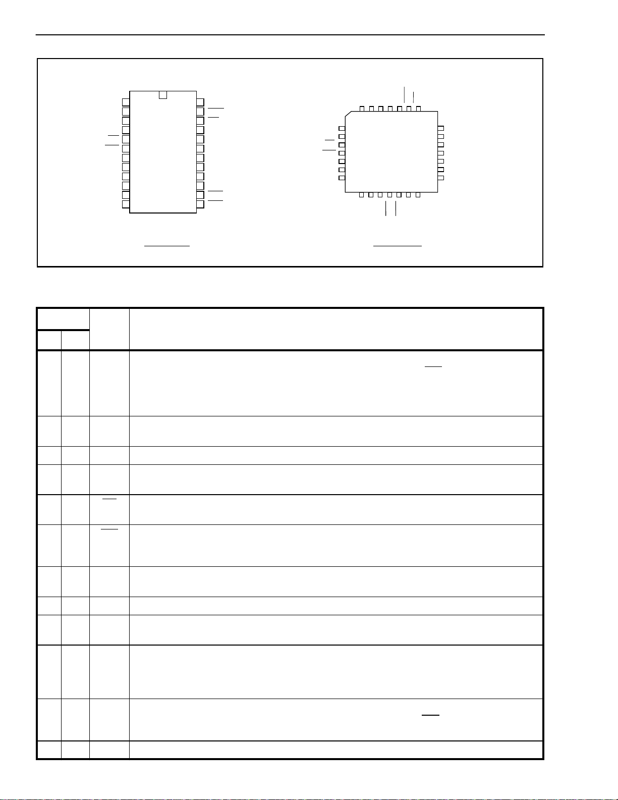
Ordering Information
MT8941BE 24 Pin Plastic DIP (600 mil)
MT8941BP 28 Pin PLCC
-40°C to +85°C
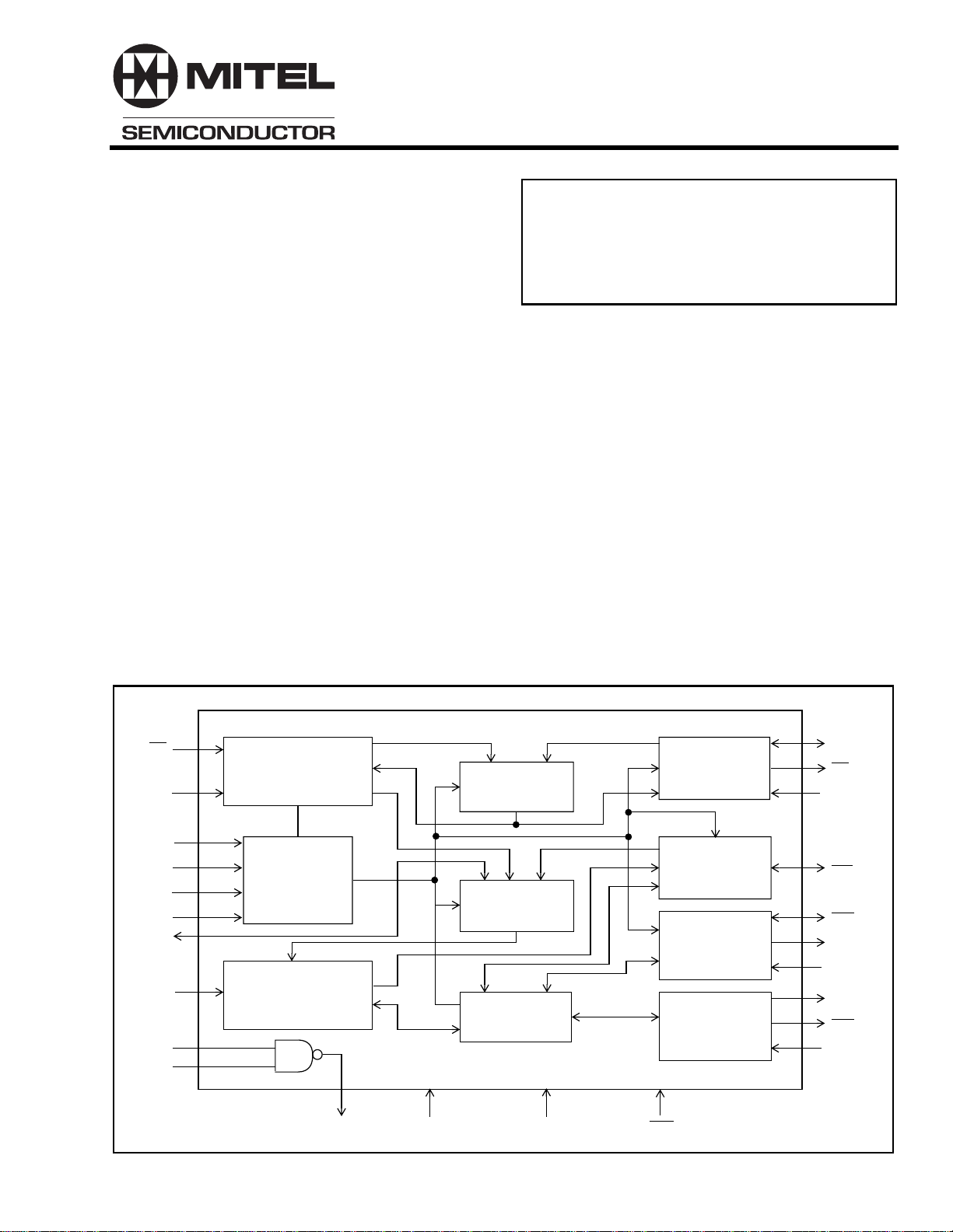
Description
The MT8941B is a dual digital phase-locked loop
providing the timing and synchronization signals for
the T1 or CEPT transmission links and the ST-BUS.
The first PLL provides the T1 clock (1.544 MHz)
synchronized to the input frame pulse at 8 kHz. The
timing signals for the CEPT transmission link and the
ST-BUS are provided by the second PLL locked to an
internal or an external 8 kHz frame pulse signal.
The MT8941B offers improved jitter performance
over the MT8940. The two devices also have some
functional differences, which are listed in the section
on “Differences between MT8941B and MT8940”.
F0i
C12i
MS0
MS1
MS2
MS3
C8Kb
C16i
DPLL #1
2:1 MUX
Mode
Selection
Logic
DPLL #2
Ai
Bi
Yo V
DD
Input
Selector
Clock
Generator
V
SS
Variable
Clock
Control
Frame Pulse
Control
4.096 MHz
Clock
Control
2.048 MHz
Clock
Control
RST
CVb
CV
ENCV
F0b
C4b
C4o
ENC4o
C2o
C2o
ENC2o
Figure 1 - Functional Block Diagram
1
Page 2
MT8941B CMOS
F0i
F0b
1
2
3
4
5
6
7
8
9
10
11
12
ENVC
MS0
C12i
MS1
MS2
C16i
ENC4o
C8Kb
C4o
VSS
Pin Description
24
23
22
21
20
19
18
17
16
15
14
13
VDD
RST
CV
CVb
Yo
Bi
Ai
MS3
ENC2o
C2o
C2o
C4b
ENC4o
Figure 2 - Pin Connections
NC
MS1
F0i
F0b
MS2
C16i
5
6
7
8
9
10
11
NC
C12i
4
3
12
13
C4o
C8Kb
28 PIN PLCC24 PIN PDIP
MS0
2
•
14
VSS
ENCV
VDD
1
28
15
16
C4b
C2o
RST
27
17
C2o
CV
26
18
NC
25
24
23
22
21
20
19
NC
CVb
Yo
Bi
Ai
MS3
ENC2o
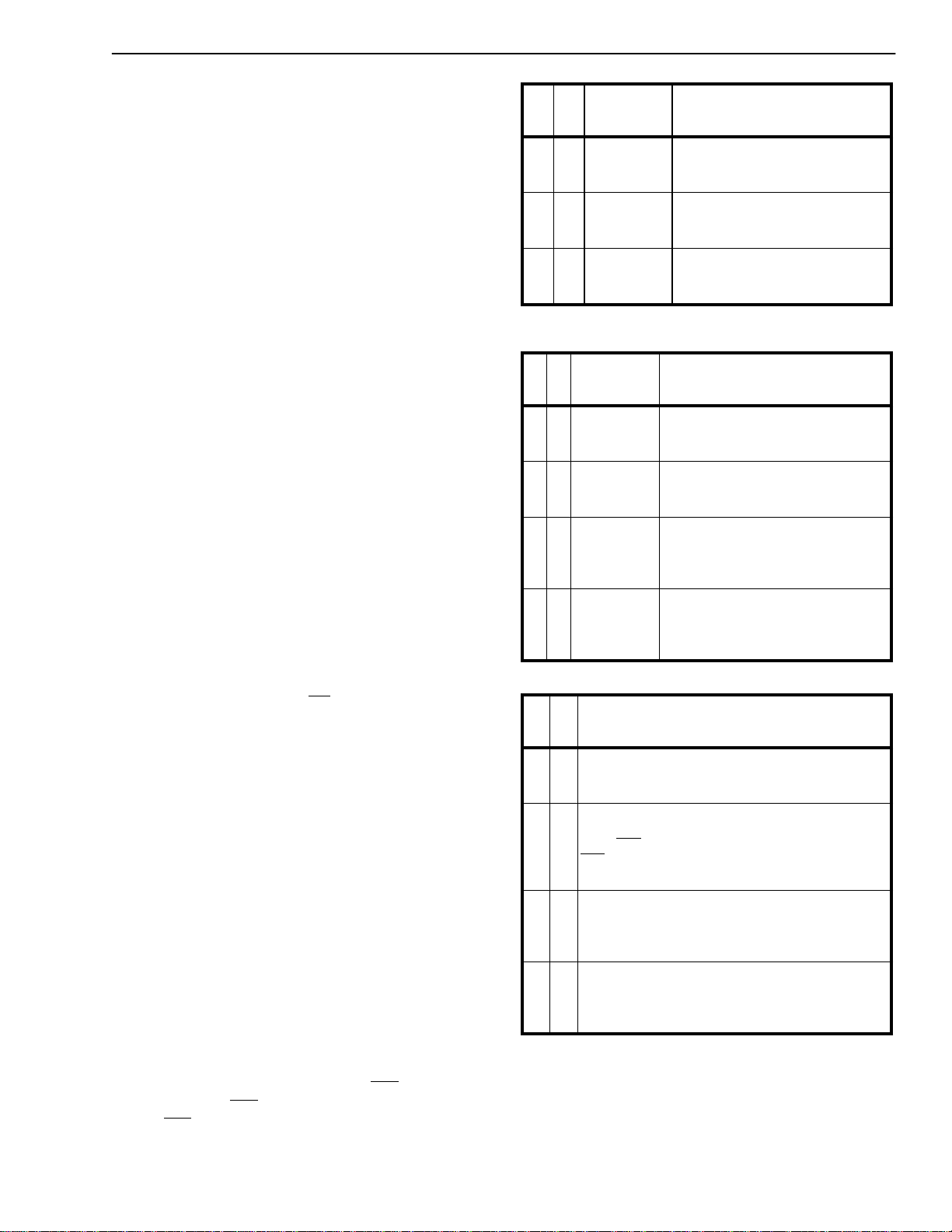
Pin #
Name Description
DIP PLCC
11ENCVVariab le cloc k enab le (TTL compatible input) - This input directly controls the three states
of CV (pin 22) under all modes of operation. When HIGH, enables CV and when LOW, puts
it in high impedance condition. It also controls the three states of CVb signal (pin 21) if MS1
is LOW. When ENCV is HIGH, the pin CVb is an output and when LOW, it is in high
impedance state. However, if MS1 is HIGH, CVb is always an input.
2 2 MS0 Mode select ‘0’ input (TTL compatible) - This input in conjunction with MS1 (pin 4) selects
the major mode of operation for both DPLLs. (Refer to Tables 1 and 2.)
3 3 C12i 12.352 MHz Clock input (TTL compatible) - Master clock input for DPLL #1.
4 6 MS1 Mode select-1 input (TTL compatible) - This input in conjunction with MS0 (pin 2) selects
the major mode of operation for both DPLLs. (Refer to Tables 1 and 2.)
57 F0i Frame pulse input (TTL compatible) - This is the frame pulse input at 8 kHz. DPLL #1
locks to the falling edge of this input to generate T1 (1.544 MHz) clock.
68F0b Frame pulse Bidirectional (TTL compatible input and Totem-pole output) - Depending
on the minor mode selected for DPLL #2, it provides the 8 kHz frame pulse output or acts as
an input to an external frame pulse.
7 9 MS2 Mode select-2 input (TTL compatible) - This input in conjunction with MS3 (pin 17) selects
the minor mode of operation for DPLL #2. (Refer to Table 3.)
8 10 C16i 16.384 MHz Clock input (TTL compatible) - Master clock input for DPLL #2.
911EN
Enable 4.096 MHz clock (TTL compatible input) - This active high input enables C4o (pin
C4o
11) output. When LOW, the output C4o is in high impedance condition.
10 12 C8Kb Clock 8 kHz Bidirectional (TTL compatible input and Totem-pole output) - This is the 8
kHz input signal on the falling edge of which the DPLL #2 locks during its NORMAL mode.
When DPLL #2 is in SINGLE CLOCK mode, this pin outputs an 8 kHz internal signal
provided by DPLL #1 which is also connected internally to DPLL #2.
11 13 C4o Clock 4.096 MHz (Three state output) - This is the inverse of the signal appearing on pin
13 (C4b) at 4.096 MHz and has a rising edge in the frame pulse (F0b) window. The high
impedance state of this output is controlled by ENC4o (pin 9).
12 14 V
2
Ground (0 Volt)
SS
Page 3
CMOS MT8941B
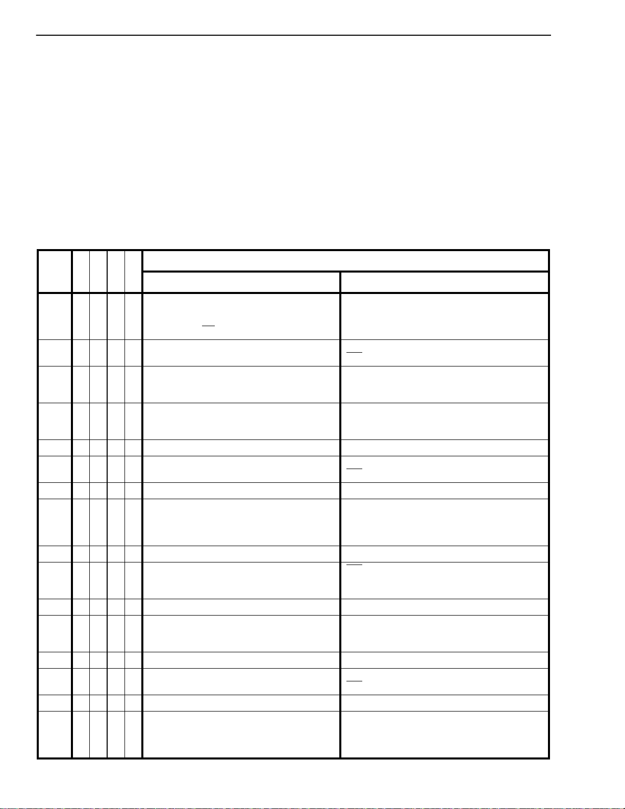
Pin Description (continued)
Pin #
Name Description
DIP PLCC
13 15 C4b Clock 4.096 MHz- Bidirectional (TTL compatible input and Totem-pole output) - When
the mode select bit MS3 (pin 17) is HIGH, it provides the 4.096 MHz clock output with the
falling edge in the frame pulse (F0b) window. When pin 17 is LOW, C4b is an input to an
external clock at 4.096 MHz.
14 16 C2o Clock 2.048 MHz (Three state output) - This is the divide by two output of C4b (pin 13) and
has a falling edge in the frame pulse (F0b) window. The high impedance state of this output
is controlled by EN
15 17 C2o Clock 2.048 MHz (Three state output) - This is the divide by two output of C4b (pin 13) and
has a rising edge in the frame pulse (F0b) window . The high impedance state of this output is
controlled by EN
16 19 EN
Enable 2.048 MHz clock (TTL compatible input) - This active high input enables both C2o
C2o
and C2o outputs (pins 14 and 15). When LOW, these outputs are in high impedance
condition.
17 20 MS3 Mode select 3 input (TTL compatible) - This input in conjunction with MS2 (pin 7) selects
the minor mode of operation for DPLL #2. (Refer to Table 3.)
C2o
C2o
(pin 16).
(pin 16).
18,1921,22Ai, Bi Inputs A and B (TTL compatible) -These are the two inputs of the uncommitted NAND
gate.
20 23 Y
Output Y (Totem pole output) - Output of the uncommitted NAND gate.
o
21 24 CVb Variable clock Bidirectional (TTL compatible input and Totem-pole output) - When
acting as an output (MS1-LOW) during the NORMAL mode of DPLL #1, this pin provides the
1.544 MHz clock locked to the input frame pulse F0i (pin 5). When MS1 is HIGH, it is an
input to an external clock at 1.544 MHz or 2.048 MHz to provide the internal signal at 8 kHz
to DPLL #2.
22 26 CV Variable clock (Three state output) - This is the inverse output of the signal appearing on
pin 21, the high impedance state of which is controlled by ENCV(pin 1).
23 27 RST Reset (Sc hmitt trigger input) - This input (activ e LO W) puts the MT8941B in its reset state.
To guarantee proper operation, the device must be reset after power-up. The time constant
for a power-up reset circuit (see Figures 9-13) must be a minim um of five times the rise time
of the power supply. In normal operation, the RST pin must be held low for a minimum of
60nsec to reset the device.
24 28 V
4,
DDVDD
NC No Connection.
(+5V) Power supply.
5,
18,
25
3
Page 4
MT8941B CMOS
Functional Description
The MT8941B is a dual digital phase-locked loop
providing the timing and synchronization signals to
the interface circuits for T1 and CEPT (30+2)
Primary Multiplex Digital Transmission links. As
shown in the functional block diagram (see Figure 1),
the MT8941B has two digital phase-locked loops
(DPLLs), associated output controls and the mode
selection logic circuits. The two DPLLs, although
similar in principle, operate independently to provide
T1 (1.544 MHz) and CEPT (2.048 MHz) transmission
clocks and ST-BUS timing signals.
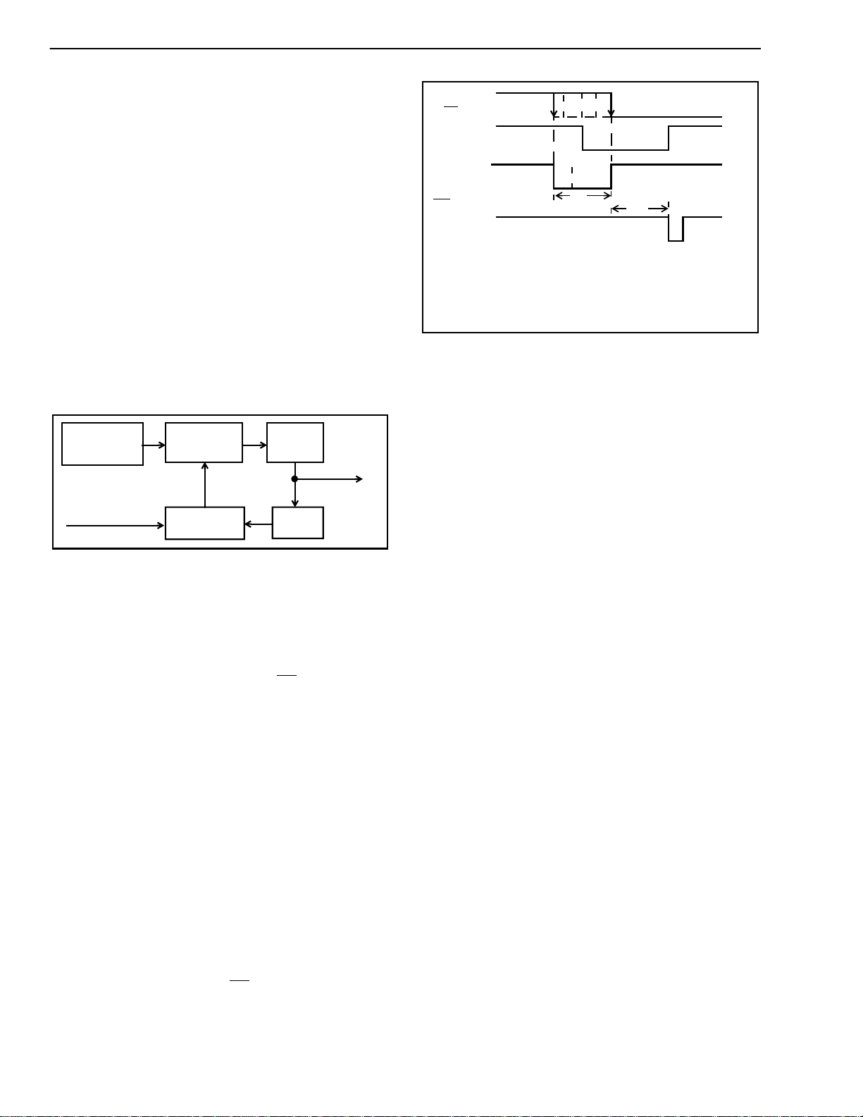
The principle of operation behind the two DPLLs is
shown in Figure 3. A master clock is divided down to
8 kHz where it is compared with the 8 kHz input, and
depending on the output of the phase comparison,
the master clock frequency is corrected.
Master clock
(12.352 MHz /
16.384 MHz)
Input (8 kHz)
The MT8941B achieves the frequency correction in
both directions by using three methods; speed-up,
slow-down and no-correction.
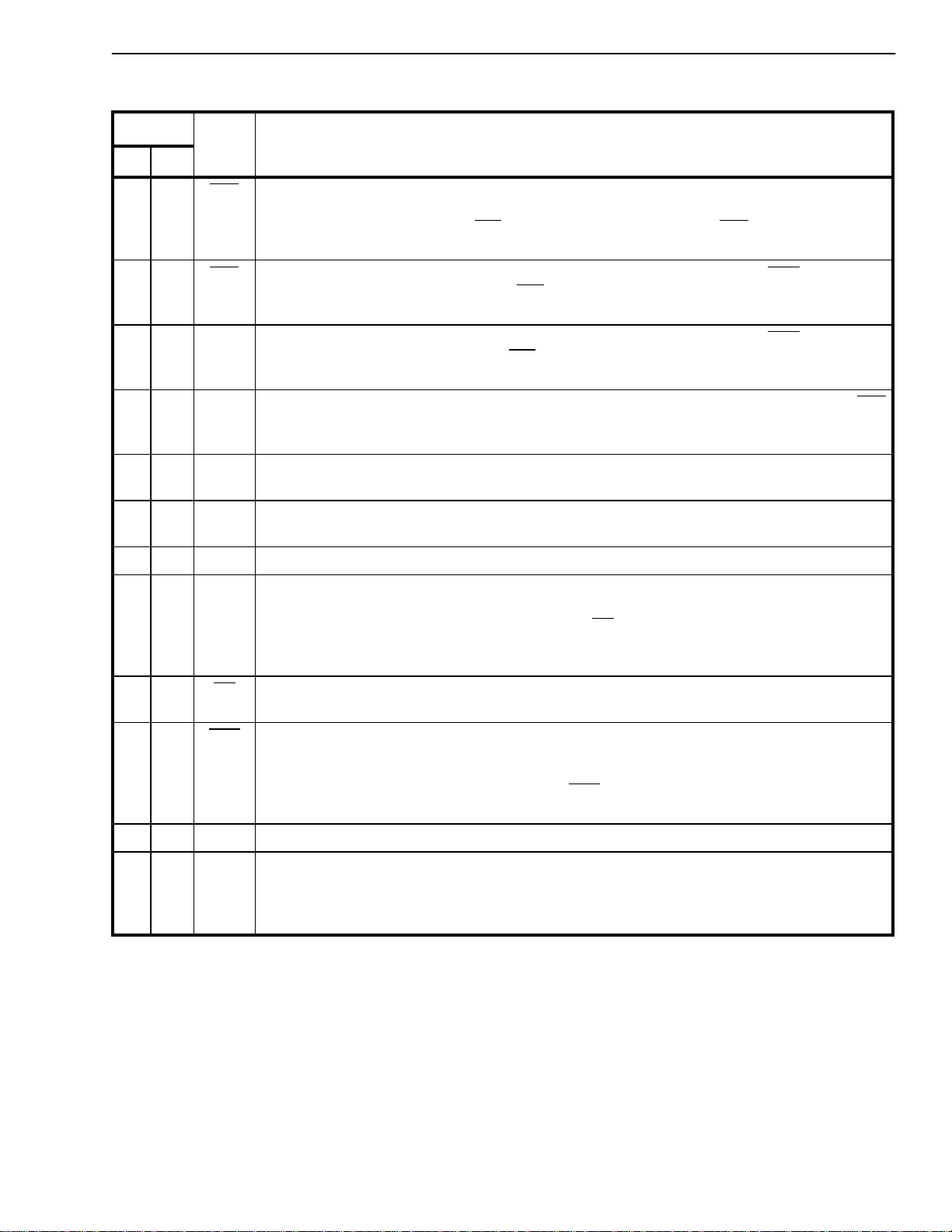
As shown in Figure 4, the falling edge of the 8 kHz
input signal (C8Kb for DPLL #2 or F0i for DPLL # 1)
is used to sample the internally generated 8 kHz
clock and the correction signal (CS) once in every
frame (125 µs). If the sampled CS is “1”, then the
DPLL makes a speed-up or slow-down correction
depending upon the sampled value of the internal 8
kHz signal. A sampled ”0” or “1” causes the
frequency correction circuit to respectively stretch or
shrink the master clock by half a period at one
instant in the frame. If the sampled CS is “0”, then
the DPLL makes no correction on the master clock
input. Note that since the internal 8 kHz signal and
the CS signal are derived from the master clock, a
correction will cause both clocks to stretch or shrink
simultaneously by an amount equal to half the period
of the master clock.
Once in synchronization, the falling edge of the
reference signal (C8Kb or F0i) will be aligned with
either the falling or the rising edge of CS. It is aligned
with the rising edge of CS when the reference signal
is slower than the internal 8 kHz signal. On the other
hand, the falling edge of the
Frequency
Correction
Phase
Comparison
÷ 8
÷ 193 /
÷ 256
Figure 3 - DPLL Principle
Output
(1.544 MHz /
2.048 MHz)
C8Kb (DPLL #2)
F0i (DPLL #1)
or
l
Interna
8 kHz
correction
CS
F0b
(DPLL #2)
DPLL #1:
DPLL #2:
where, T
for DPLL #1 and T
for DPLL #2.
speed-up
region
= 4 × T
t
CS
tCS = 512 × T
t
CSF
is the 12.352 MHz master clock oscillator period
P12
t
CS
no-correction
± 0.5 × T
P12
± 0.5 × T
= 766 × T
P16
P16
is the 16.384 MHz master clock period
P16
sampling edge
correction
t
CSF
P12
P16
slow-down
region
Figure 4 - Phase Comparison
reference signal will be aligned with the falling edge
of CS if the reference signal is faster than the
internal 8 kHz signal.
Input-to-Output Phase Relationship
The no-correction window size is 324 ns for DPLL #1
and 32 µs for DPLL #2. It is possible for the relative
phase of the reference signal to swing inside the nocorrection window depending on its jitter and the
relative drift of the master clock. As a result, the
phase relationship between the input signal and the
output clocks (and frame pulse in case of DPLL #2)
may vary up to a maximum of window size. This
situation is illustrated in Figure 4. The maximum
phase variation for DPLL #1 is 324 ns and for DPLL
#2 it is 32µs. However, this phase difference can be
absorbed by the input jitter buffer of Mitel’s T1/CEPT
devices.
The no-correction window acts as a filter for low
frequency jitter and wander since the DPLL does not
track the reference signal inside it. The size of the
no-correction window is less than or equal to the size
of the input jitter buffer on the T1 and CEPT devices
to guarantee that no slip will occur in the received
T1/CEPT frame.
The circuit will remain in synchronization as long as
the input frequency is within the lock-in range of the
DPLLs (refer to the section on “Jitter Performance
and Lock-in Range” for further details). The lock-in
range is wide enough to meet the CCITT line rate
specification (1.544 MHz ±32 ppm and 2.048 MHz
±50 ppm) for the High Capacity Terrestrial Digital
Service.
The phase sampling is done once in a frame (8 kHz)
for each DPLL. The divisions are set at 8 and 193 for
DPLL #1, which locks to the falling edge of the input
4
Page 5
CMOS MT8941B
at 8 kHz to generate T1 (1.544 MHz) clock. For
DPLL #2, the divisions are set at 8 and 256 to
provide the CEPT/ST-BUS clock at 2.048 MHz
synchronized to the falling edge of the input signal (8
kHz). The master clock source is specified to be
12.352 MHz for DPLL #1 and 16.384 MHz for DPLL
#2 over the entire temperature range of operation.
The inputs MS0 to MS3 are used to select the
operating mode of the MT8941B, see Tables 1 to 4.
All the outputs are controlled to the high impedance
condition by their respective enable controls. The
uncommitted NAND gate is available for use in
applications involving Mitel’s MT8976/ MH89760 (T1
Interfaces) and MT8979/MH89790 (CEPT
Interfaces).
Modes of Operation
The operation of the MT8941B is categorized into
major modes and minor modes. The major modes
are defined for both DPLLs by the mode select pins
MS0 and MS1. The minor modes are selected by
pins MS2 and MS3 and are applicable only to DPLL
#2. There are no minor modes for DPLL #1.
Major modes of DPLL #1
DPLL #1 can be operated in three major modes as
selected by MS0 and MS1 (Table 1). When MS1 is
LOW, it is in NORMAL mode, which provides a T1
(1.544 MHz) clock signal locked to the falling edge
of the input frame pulse F0i (8 kHz). DPLL #1
requires a master clock input of 12.352 MHz (C12i).
In the second and third major modes (MS1 is HIGH),
DPLL #1 is set to DIVIDE an external 1.544 MHz or
2.048 MHz signal applied at CVb (pin 21). The
division can be set by MS0 to be either 193 (LOW) or
256 (HIGH). In these modes, the 8 kHz output at
C8Kb is connected internally to DPLL #2, which
operates in SINGLE CLOCK mode.
Major modes of DPLL #2
There are four major modes for DPLL #2 selectable
by MS0 and MS1, as shown in Table 2. In all these
modes DPLL #2 provides the CEPT PCM30 timing,
and the ST-BUS clock and framing signals.
In NORMAL mode, DPLL #2 provides the CEPT/STBUS compatible timing signals locked to the falling
edge of the 8 kHz input signal (C8Kb). These
signals are 4.096 MHz (C4o and
MHz (C2o and C2o) clocks, and the 8 kHz frame
pulse (F0b) derived from the 16.384 MHz master
clock. This mode can be the same as the FREERUN mode if the C8Kb pin is tied to VDDor VSS.
C4b) and 2.048
M
M
S
1
Mode of
Operation
Function
Provides the T1 (1.544 MHz) clock
synchronized to the falling edge of
the input frame pulse (F0i).
DPLL #1 divides the CVb input by
193. The divided output is
connected to DPLL #2.
DPLL #1 divides the CVb input by
256. The divided output is
connected to DPLL #2.
S
0
X 0 NORMAL
0 1 DIVIDE-1
1 1 DIVIDE-2
Note: X: indicates don’t care
Table 1. Major Modes of DPLL #1
M
M
S
1
Mode of
Operation
SINGLE
CLOCK-1
SINGLE
CLOCK-2
Function
Provides CEPT/ST-BUS timing
signals locked to the falling edge of
the 8 kHz input signal at C8Kb.
Provides CEPT/ST-BUS timing and
framing signals with no external
inputs, except the master clock.
Provides CEPT/ST-BUS timing
signals locked to the falling edge of
the 8 kHz internal signal provided by
DPLL #1.
Provides CEPT/ST-BUS timing
signals locked to the falling edge of
the 8 kHz internal signal provided by
DPLL #1.
S
0
0 0 NORMAL
1 0 FREE-RUN
01
11
Table 2. Major Modes of DPLL #2
M
M
S
S
2
3
11
01
00
10
Provides CEPT/ST-BUS 4.096 MHz and 2.048
MHz clocks and 8kHz frame pulse depending on
the major mode selected.
Provides CEPT/ST-BUS 4.096 MHz & 2.048 MHz
clocks depending on the major mode selected
while
F0b has no effect on the operation of DPLL #2
unless it is in FREE-RUN mode.
Overrides the major mode selected and accepts
properly phase related external 4.096 MHz clock
and 8 kHz frame pulse to provide the ST-BUS
compatible clock at 2.048 MHz.
Overrides the major mode selected and accepts a
4.096 MHz external clock to provide the ST-BUS
clock and frame pulse at 2.048 MHz and 8 kHz,
respectively.
Functional Description
F0b acts as an input. However, the input on
Table 3. Minor Modes of DPLL #2
In FREE-RUN mode, DPLL #2 generates the standalone CEPT and ST-BUS timing and framing signals
with no external inputs except the master clock set at
16.384 MHz. The DPLL makes no correction in this
configuration and provides the timing signals without
any jitter.
5
Page 6
MT8941B CMOS
The operation of DPLL #2 in SINGLE CLOCK-1
mode is identical to SINGLE CLOCK-2 mode,
providing the CEPT and ST-BUS compatible timing
signals synchro-nized to the internal 8 kHz signal
obtained from DPLL#1 in DIVIDE mode. When
10) and DPLL #2 locks to the falling edge to provide
the CEPT and ST-BUS compatible timing signals.
This is in contrast to the Normal mode where these
timing signals are synchronized with the falling edge
of the 8 kHz signal on C8Kb.
SINGLE CLOCK-1 mode is selected for DPLL #2, it
automatically selects the DIVIDE-1 mode for DPLL
#1, and thus, an external 1.544 MHz clock signal
Minor modes of DPLL #2
applied at CVb (pin 21) is divided by DPLL #1 to
generate the internal signal at 8 kHz on to which
DPLL #2 locks. Similarly when SINGLE CLOCK-2
mode is selected, DPLL #1 is in DIVIDE-2 mode,
The minor modes for DPLL #2 depends upon the
status of the mode select bits MS2 and MS3 (pins 7
and 17).
with an external signal of 2.048 MHz providing the
internal 8 kHz signal to DPLL #2. In both these
modes, this internal signal is available on C8Kb (pin
M
M
M
Mode
S
#
0 0000
1 0 0 0 1 NORMAL MODE
2 0010
3 0011
4 0 1 0 0 DIVIDE-1 MODE Same as mode ‘0’.
5 0 1 0 1 DIVIDE-1 MODE
6 0 1 1 0 DIVIDE-1 MODE Same as mode 2.
7 0111
8 1 0 0 0 NORMAL MODE Same as mode ‘0’.
9 1001
10 1 0 1 0 NORMAL MODE Same as mode 2.
11 1011
12 1 1 0 0 DIVIDE-2 MODE Same as mode ‘0’.
13 1101
14 1 1 1 0 DIVIDE-2 MODE Same as mode 2.
15 1111
S
0
1
M
S
S
2
3
NORMAL MODE:
Provides the T1 (1.544 MHz) clock
synchronized to the falling edge of the input
frame pulse (
NORMAL MODE
NORMAL MODE NORMAL MODE:
DIVIDE-1 MODE:
Divides the CVb input by 193. The divided
output is connected to DPLL #2.
NORMAL MODE
NORMAL MODE
DIVIDE-2 MODE SINGLE CLOCK-2 MODE:
DIVIDE-2 MODE:
Divides the CVb input by 256. The divided
output is connected to DPLL#2.
DPLL #1 DPLL #2
F0i).
Operating Modes
Properly phase related External 4.096 MHz
clock and 8 kHz frame pulse provide the STBUS clock at 2.048 MHz.
NORMAL MODE:
F0b is an input but has no function in this mode.
External 4.096 MHz provides the ST-BUS clock
and Frame Pulse at 2.048 MHz and 8 kHz,
respectively.
Provides the CEPT/ST-BUS compatible timing
signals locked to the 8 kHz input signal (C8Kb).
SINGLE CLOCK-1 MODE
F0b is an input but has no function in this mode.
SINGLE CLOCK-1 MODE:
Provides the CEPT/ST-BUS compatible timing
signals locked to the 8 kHz internal signal
provided by DPLL #1.
F0b is an input and DPLL #2 locks on to
it only if it is at 16 kHz to provide the ST-BUS
control signals.
FREE-RUN MODE:
Provides the ST-BUS timing signals with no
external inputs except the master clock.
F0b is an input but has no function in this mode.
SINGLE CLOCK-2 MODE:
Provides the CEPT/ST-BUS compatible timing
signals locked to the 8 kHz internal signal
provided by DPLL #1.
Table 4. Summary of Modes of Operation - DPLL #1 and #2
6
Page 7
CMOS MT8941B
When MS3 is HIGH, DPLL #2 operates in any of the
major modes selected by MS0 and MS1. When MS3
is LOW, it overrides the major mode selected and
DPLL#2 accepts an external clock of 4.096 MHz on
C4b (pin 13) to provide the 2.048 MHz clocks (C2o
and C2o) and the 8 kHz frame pulse (F0b)
compatible with the ST-BUS format. The mode select
bit MS2 controls the direction of the signal on F0b
(pin 6).
When MS2 is LOW, the F0b pin is an 8 kHz frame
pulse input. This input is effective only when MS3 is
also LOW and pin C4b is fed by a 4.096 MHz clock,
which has a proper phase relationship with the
signal on F0b (refer Figure 18). Otherwise, the input
on pin F0b will have no bearing on the operation of
DPLL #2, unless it is in FREE-RUN mode as
selected by MS0 and MS1. In FREE-RUN mode,
the input on F0b is treated the same way as the
C8Kb input is in NORMAL mode. The frequency of
the signal on F0b should be 16 kHz for DPLL #2 to
lock and generate the ST-BUS compatible clocks at
4.096 MHz and 2.048 MHz.
When MS2 is HIGH, the F0b pin provides the frame
pulse output compatible with the ST-BUS format and
locked to the internal or external input signal as
determined by the other mode select pins.
Table 4 summarizes the modes of the two DPLL. It
should be noted that each of the major modes
selected for DPLL #2 can have any of the minor
modes, although some of the combinations are
Mode
#
0 i:8 i:4.096 i:X o:1.544
1 i:X o:4.096 i:8 o:1.544
2 o:8 i:4.096 i:X o:1.544
3 o:8 o:4.096 i:8 o:1.544
4 i:8 i:4.096 i:X i:1.544
5 i:X o:4.096 o:8 i:1.544
6 o:8 i:4.096 i:X i:1.544
7 o:8 o:4.096 o:8 i:1.544
8 i:8 i:4.096 i:X o:1.544
9 i:16 o:4.096 i:X o:1.544
10 o:8 i:4.096 i:X o:1.544
11 o:8 o:4.096 i:X o:1.544
12 i:8 i:4.096 i:X i:2.408
13 i:X o:4.096 o:8 i:2.408
14 o:8 i:4.096 i:X i:2.408
15 o:8 o:4.096 o:8 i:2.408
F0b
(kHz)
C4b
(MHz)
C8Kb
(kHz)
CVb
(MHz)
Table 5. Functions of the Bidirectional Signals
in Each Mode
Notes: i : Input
o : Output
X : “don’t care” input. Connect to VDD or V
SS.
functionally similar. The required operation of both
DPLL #1 and DPLL #2 must be considered when
determining MS0-MS3.
The direction and frequency of each of the
bidirectional signals are listed in Table 5 for each of
the given modes in Table 4.
Jitter Performance and Lock-in Range
The output jitter of a DPLL is composed of the
intrinsic jitter, measured when no jitter is present at
the input, and the output jitter resulting from jitter on
the input signal. The spectrum of the intrinsic jitter
for both DPLLs of the MT8941B is shown in Figure 5.
The typical peak-to-peak value for this jitter is
0.07UI. The transfer function, which is the ratio of
the output jitter to the input jitter (both measured at a
particular frequency), is shown in Figure 6 for DPLL
#1 and Figure 7 for DPLL #2. The transfer function is
measured when the peak-to-peak amplitude of the
sinusoidal input jitter conforms to the following:
10 Hz - 100 Hz : 13.6 µs
100 Hz - 10 kHz : 20 dB/decade roll-off
> 10 kHz : 97.2 ns
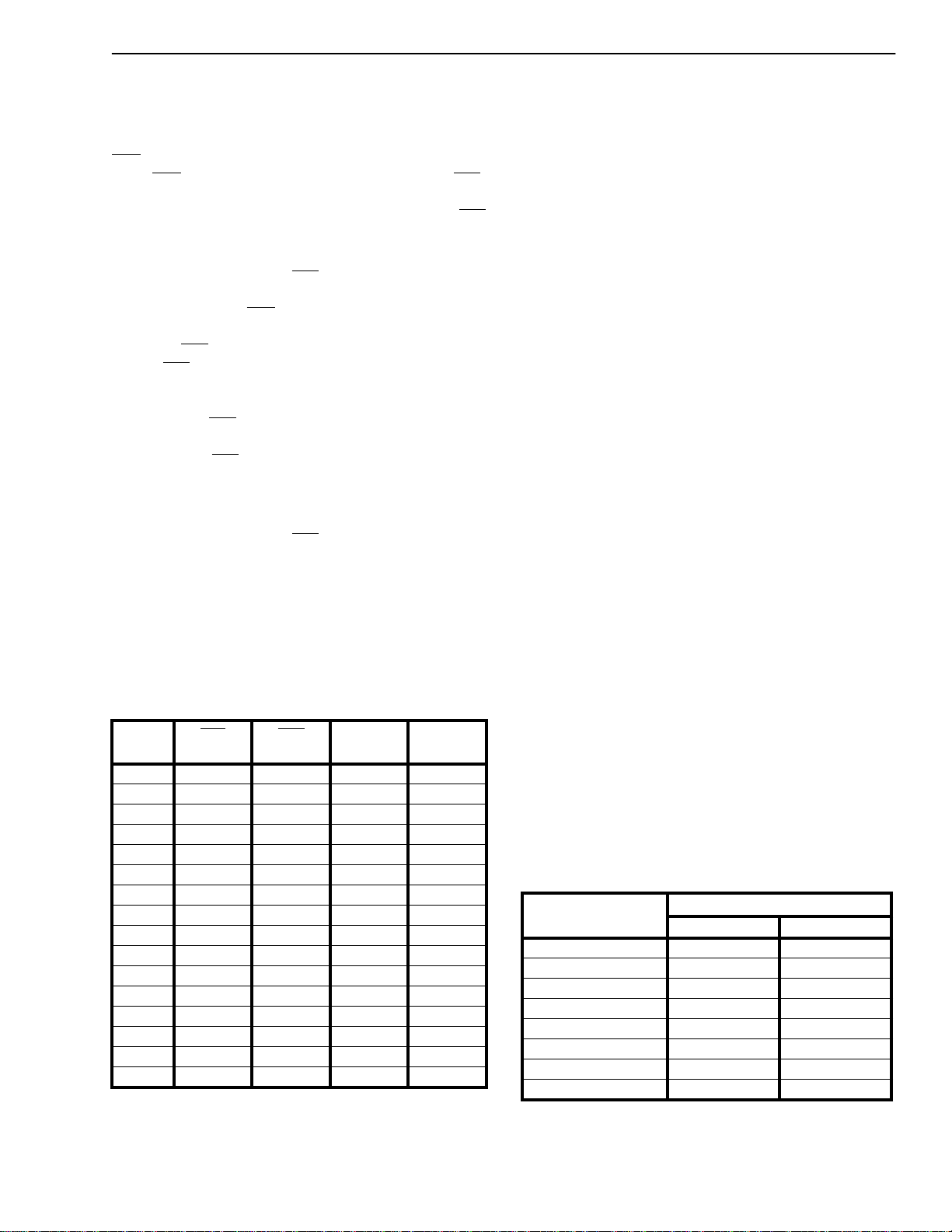
The ability of a DPLL to phase-lock the input signal
to the reference signal and to remain lock ed depends
upon its lock-in range. The lock-in r ange of the DPLL
is specified in terms of the maximum frequency
variation in the 8 kHz reference signal. It is also
directly affected by the oscillator frequency
tolerance. Table 6 lists different values for the lock-in
range and the corresponding oscillator frequency
tolerance for DPLL #1 and DPLL #2. The smaller
the tolerance value, the larger the lock-in range.
The T1 and CEPT standards specify that, for free
running equipment, the output clock tolerance must
be less than or equal to ±32ppm and ±50ppm
respectively. This requirement restr icts the
Oscillator Clock*
Tolerance (±ppm)
5 2.55 1.91
10 2.51 1.87
20 2.43 1.79
32 2.33 1.69
50 2.19 1.55
100 1.79 1.15
150 1.39 .75
175 1.19 .55
Lock-in Range (
DPLL #1 DPLL #2
T ab le 6. Loc k-in Range vs. Oscillator Frequency
T olerance
* Please refer to the section on “Jitter Performance and Lock-in
Range” for recommended oscillator tolerances for DPLL #1 & #2.
±Hz)
7
Page 8

MT8941B CMOS
Figure 5- The Spectrum of the Inherent Jitter for either PLL
Figure 6 - The Jitter Transfer Function for PLL1
Figure 7 -The Jitter Transfer Function for PLL2
8
Page 9

CMOS MT8941B
oscillators of DPLL #1 and DPLL #2 to have
maximum tolerances of ±32ppm and ±50ppm
respectively.
However, if DPLL #1 and DPLL #2 are daisy-chained
as shown in Figures 9 and 10, the output clock
tolerance of DPLL #1 will be equal to that of the
DPLL #2 oscillator when DPLL #2 is free-running. In
this case, the oscillator tolerance of DPLL #1 has no
impact on its output clock tolerance. For this reason,
a) Distributed Timing
Data Bus
8 kHz Reference Signal
M
U
X
it is recommended to use a ±32 ppm oscillator for
DPLL #2 and a ±100 ppm oscillator for DPLL #1.
Differences between MT8941B and
MT8940
The MT8941B and MT8940 are pin and mode
compatible for most applications. However, the user
should take note of the following differences between
the two parts.
Line Card 1
MT8940
Clocks
8 kHz Reference Signal
b) Centralized Timing
8 kHz Reference Signal
M
U
X
MT8941B
Clocks
Data Bus
MT8940
Line Card n
Clocks
Line Card 1
Line Card n
8 kHz Reference Signal
Figure 8 - Application Differences between the MT8940 and MT8941B
9
Page 10

MT8941B CMOS
Besides the improved jitter performance, the
MT8941B differs from the MT8940 in three other
areas:
1. Input pins on the MT8941B do not incorporate
internal pull-up or pull-down resistors. In
addition, the output configuration of the
bidirectional C8Kb pin has been converted from
an open drain output to a Totem-pole output.
2. The MT8941B includes a no-correction window
to filter out low frequency jitter and wander as
illustrated in Figure 4. Consequently, there is no
constant phase relationship between reference
signal F0i of DPLL # 1 or C8Kb of DPLL #2 and
the output clocks of DPLL #1 or DPLL #2.
Figure 4 shows the new phase relationship
between C8Kb and the DPLL #2 output clocks.
Figure 8 illustrates an application where the
MT8941B cannot replace the MT8940 and
suggests an alternative solution.
3. The MT8941B must be reset after power-up in
order to guarantee proper operation, which is not
the case for the MT8940.
4. For the MT8941B, DPLL #2 locks to the falling
edge of the C8Kb reference signal. DPLL#2 of
the MT8940 locks on to the rising edge of C8Kb.
5. While the MT8940 is available only in a 24 pin
plastic DIP, the MT8941B has an additional 28
pin PLCC package option.
Applications
The following figures illustrates how the MT8941B
can be used in a minimum component count
approach in providing the timing and synchronization signals for the Mitel T1 or CEPT interfaces,
and the ST-BUS. The hardware selectable modes
and the independent control over each PLL adds
flexibility to the interface circuits. It can be easily
reconfigured to provide the timing and control signals
for both the master and slave ends of the link.
Synchronization and Timing Signals for the T1
Transmission Link
Figures 9 and 10 show examples of how to generate
the timing signals for the master and slave ends of a
T1 link. At the master end of the link (Figure 9),
DPLL #2 is the source of the ST-BUS signals derived
from the crystal clock. The frame pulse output is
looped back to DPLL #1 (in NORMAL mode), which
locks to it to generate the T1 line clock. The timing
relationship between the 1.544 MHz T1 clock and the
2.048 MHz ST-BUS clock meets the requirements of
the MH89760/760B. The crystal clock at 12.352
MHz is used by DPLL #1 to generate the 1.544 MHz
clock, while DPLL #2 (in FREE-RUN mode) uses the
16.384 MHz crystal oscillator to generate the STBUS clocks for system timing. The generated STBUS signals can be used to synchronize the system
and the switching equipment at the master end.
Crystal Clock
(12.352 MHz)
Crystal Clock
(16.384 MHz)
10
MT8980/81
ST-BUS
SWITCH
(1.544 Mbps)
MS0
MS1
MS2
MS3
F0i
C12i
EN
CV
C8Kb
C16i
EN
C4o
EN
C2o
V
SS
MT8941B
RST
C
V
DD
CVb
C4b
C2o
F0b
MH89760B
C1.5i
C2i
F0i
V
DD
R
DPLL #1 - NORMAL (MS0 = X; MS1 = 0)
DPLL #2 - FREE-RUN (MS0=1; MS2=1; MS3=1)
DSTi
DSTo
CSTi
CSTo
TxT
TRANSMIT
TxR
RxT
RxR
Mode of Operation for the MT8941B
RECEIVE
Figure 9 - Synchronization at the Master End of the T1 Transmission Link
T1
LINK
Page 11

CMOS MT8941B
Crystal Clock
(12.352 MHz)
Crystal Clock
(16.384 MHz)
Crystal Clock
(16.384 MHz)
MT8980/81
SWITCH
(1.544 Mbps)
MS0
MS1
MS2
MS3
F0i
C12i
EN
CV
C8Kb
C16i
EN
C4o
EN
C2o
V
SS
MT8941B
RST
C
V
DD
CVb
C4b
C2o
F0b
MH89760B
C1.5i
C2i
F0i
E8Ko
R
V
DD
DPLL #1 - NORMAL ( MS1=0)
DPLL #2 - NORMAL (MS0=0; MS1=0; MS2=1; MS3=1)
DSTi
DSTo
CSTi
CSTo
TxT
TxR
RxT
RxR
Mode of Operation for the MT8941B
TRANSMIT
RECEIVE
Figure 10 - Synchronization at the Slave End of the T1 Transmission Link
MS0
MS1
MS2
MS3
F0i
C12i
EN
CV
C8Kb
C16i
EN
C4o
EN
C2o
V
SS
MT8941B
RST
V
DD
C4b
C2o
F0b
Y
MH89790B
DSTi
C2i
F0i
o
DSTo
CSTi0
CSTi1
CSTo
OUTA
OUTB
RxT
RxR
TRANSMIT
RECEIVE
MT8980/81
ST-BUS
SWITCH
CEPT
PRIMARY
MULTIPLEX
DIGITAL
ST-BUS
T1
LINK
LINK
V
DD
C
R
Figure 11 - Synchronization at the Master End of the CEPT Digital Transmission Link
At the slave end of the link (Figure 10) both the
DPLLs are in NORMAL mode, with DPLL #2
providing the ST-BUS timing signals locked to the 8
kHz frame pulse (E8Ko) extracted from the received
signal on the T1 line. The regenerated frame pulse
is looped back to DPLL #1 to provide the T1 line
clock, which is the same as the master end.
The 12.352 MHz and 16.384 MHz crystal clock
sources are necessary for DPLL #1 and #2,
respectively.
Mode of Operation for the MT8941B
DPLL #1 - NOT USED
DPLL #2 - FREE-RUN (MS0=1; MS1=0; MS2=1; MS3=1)
Synchronization and Timing Signals for the
CEPT Transmission Link
The MT8941B can be used to provide the timing and
synchronization signals for the MH89790/790B,
Mitel’s CEPT (30+2) Digital Trunk Interface Hybrid.
Since the operational frequencies of the ST-BUS and
the CEPT primary multiplex digital trunk are the
same, only DPLL #2 is required.
11
Page 12

MT8941B CMOS
MT8941B
V
DD
C4b
C2o
F0b
Y
o
V
DD
R
Crystal Clock
(16.384 MHz)
MS0
MS1
MS2
MS3
F0i
C12i
EN
CV
C8Kb
C16i
EN
C4o
EN
C2o
V
SS
RST
C
Figure 12 - Synchronization at the Slave End of the CEPT Digital Transmission Link
Figures 11 and 12 show how the MT8941B can be
used to synchronize the ST-BUS to the CEPT
transmission link at the master and slave ends.
Generation of ST-BUS Timing Signals
The MT8941B can source the properly formatted STBUS timing and control signals with no external
inputs except the crystal clock. This can be used as
the standard timing source for ST-BUS systems or
any other system with similar clock requirements.
MT8980/81
MH89790B
DSTi
C2i
F0i
E8Ko
DPLL #1 - NOT USED
DPLL #2 - NORMAL (MS0=0; MS1=0; MS2=1; MS3=1)
DSTo
CSTi0
CSTi1
CSTo
OUTA
OUTB
RxT
RxR
Mode of Operation for the MT8941B
TRANSMIT
RECEIVE
ST-BUS
SWITCH
CEPT
PRIMARY
MULTIPLEX
DIGITAL
LINK
Figure 13 shows two such applications using DPLL
#2. In one case, the MT8941B is in FREE-RUN
mode with an oscillator input of 16.384 MHz. In the
other case, it is in NORMAL mode with the C8Kb
input tied to VDD. For these applications, DPLL #2
does not make any corrections and therefore, the
output signals are free from jitter. DPLL #1 is
completely free.
Crystal Clock
(16.384 MHz)
12
DPLL #1 - NOT USED
DPLL #2 - FREE-RUN MODE
(MS0=1; MS1=0;MS2=1;
MS0
MS1
MS2
MS3
F0i
C12i
EN
CV
C8Kb
C16i
EN
C4o
EN
C2o
Ai
Bi
V
SS
MT8941B
V
C4o
C4b
C2o
C2o
F0b
RST
C
DD
R
MS3=1)
ST-BUS
TIMING
SIGNALS
DPLL #1 - NOT USED
DPLL #2 - NORMAL MODE
(MS0=0; MS1=0;
MS2=1; MS3=1)
V
DD
Crystal Clock
(16.384 MHz)
Figure 13 - Generation of the ST-BUS Timing Signals
MS0
MS1
MS2
MS3
F0i
C12i
EN
CV
C8Kb
C16i
EN
C4o
EN
C2o
Ai
Bi
V
SS
MT8941B
RST
C
V
DD
C4o
C4b
C2o
C2o
F0b
R
ST-BUS
TIMING
SIGNALS
V
DD
Page 13

CMOS MT8941B
Absolute Maximum Ratings*- Voltages are with respect to ground (V
) unless otherwise stated.
SS
Parameter Symbol Min Max Units
1 Supply Voltage V
2 Voltage on any pin V
3 Input/Output Diode Current I
4 Output Source or Sink Current I
5 DC Supply or Ground Current IDD/I
6 Storage Temperature T
7 Package Power Dissipation Plastic DIP
PLCC
* Exceeding these values may cause permanent damage. Functional operation under these conditions is not implied.
DD
I
IK/OK
O
ST
P
D
P
D
SS
Recommended Operating Conditions - Voltages are with respect to ground (V
Characteristics Sym Min Typ
1 Supply Voltage V
2 Input HIGH Voltage V
3 Input LOW Voltage V
4 Operating Temperature T
‡ Typical figures are at 25°C and are for design aid only: not guaranteed and not subject to production testing.
DD
IH
IL
A
4.5 5.0 5.5 V
2.0 V
V
SS
-40 25 85
‡
Max Units Test Conditions
DD
0.8 V
-0.3 7.0 V
VSS-0.3 VDD+0.3 V
-55 125
) unless otherwise stated.
SS
V
o
C
±10 mA
±25 mA
±50 mA
1200
600
mW
mW
o
C
DC Electrical Characteristics - Voltages are with respect to ground (V
VDD=5.0V±5%; VSS=0V; TA=-40 to 85°C.
Characteristics Sym Min Typ‡Max Units Test Conditions
S
U
1
2
Supply Current
P
Input HIGH voltage (For all the
inputs except pin 23)
3 Positive-going threshold
voltage (For pin 23)
I
N
4 Input LOW voltage (For all the
inputs except pin 23)
5 Negative-going threshold
voltage (For pin 23)
O
6
7 Output current LOW I
Output current HIGH I
U
T
8 Leakage current on bidirect-
ional pins and all inputs except
C12i, C16i, RST, MS1, MS0
I
V
V
V
DD
2.0 V
IH
+
IL
V
OH
OL
I
1.0 1.5 V
-
-4 mA VOH=2.4 V
4mAV
-100 -30 µA VIN=V
IL
815mA
3.0 4.0 V
) unless otherwise stated.
SS
Under clocked condition, with the
inputs tied to the same supply
rail as the corresponding pull-up
/down resistors.
0.8 V
=0.4 V
OL
SS
9 Leakage current on pins MS1,
I
IL
35 120 µAVIN=V
MS0
10 Leakage current on all three-
I
-10 ±1 +10 µAV
IL
state outputs and C12i, C16i,
RST inputs
‡ Typical figures are at 25°C and are for design aid only: not guaranteed and not subject to production testing.
DD
I/O=VSS
or V
DD
13
Page 14

MT8941B CMOS
AC Electrical Characteristics†- Voltages are with respect to g round (V
) unless otherwise stated. (Refer to Figure 14)
SS
Characteristics Sym Min Typ‡Max Units Test Conditions
1
2 CVb output (1.544 MHz) fall
3 CVb output (1.544 MHz) clock
4 CVb output (1.544 MHz) clock
5 CVb output (1.544 MHz) clock
6 CV delay (HIGH to LOW) t
7 CV delay (LOW to HIGH) t
† Timing is over recommended temperature & power supply voltages.
‡ Typical figures are at 25°C and are for design aid only: not guaranteed and not subject to production testing.
CVb output (1.544 MHz) rise
time
time
D
P
period
L
L
width (HIGH)
#1
width (LOW)
t
r1.5
t
f1.5
t
P15
t
W15H
t
W15L
15HL
15LH
6ns
85 pF Load
6 ns 85 pF Load
607 648 689 ns
318 324 ns
277 363 ns
010ns
-7 3 ns
t
W15H
V
CVb
CV
OH
V
OL
t
15HL
V
OH
V
OL
t
15LH
Figure 14 - Timing Information for DPLL #1 in NORMAL Mode
AC Electrical Characteristics†- Voltages are with respect to ground (V
Characteristics Sym Min Typ‡Max Units Test Conditions
1
2 C8Kb output (8 kHz) delay
3 C8Kb output duty cycle 66
C8Kb output (8kHz) delay
(HIGH to HIGH)
D
(LOW to LOW )
P
L
L
t
C8HH
t
C8LL
0 10 25 ns 85 pF Load
13 34 ns 85 pF Load
50
t
P15
t
f1.5
t
W15L
t
r1.5
) unless otherwise stated. (Refer to Figure 15)
SS
%
%
In Divide -1 Mode
In Divide - 2 Mode
4 Inverted clock output delay
#1
(HIGH to LOW )
5 Inverted clock output delay
(LOW to HIGH)
† Timing is over recommended temperature & power supply voltages.
‡ Typical figures are at 25°C and are for design aid only: not guaranteed and not subject to production testing.
14
t
ICHL
t
ICLH
01025ns
0 7 18 ns
Page 15

CVb
CMOS MT8941B
V
IH
V
IL
CV
C8Kb
F0b
C4b
t
ICHL
V
OH
V
OL
t
C8HH
V
OH
V
OL
t
ICLH
t
C8LL
Figure 15 - DPLL #1 in DIVIDE Mode
t
WFP
V
OH
V
OL
t
FPL
t
W4oH
V
OH
V
OL
t
W4oL
t
FPH
t
4oLH
t
4oHL
t
fC4
t
P4o
t
rC4
C4o
C2o
C2o
V
OH
V
OL
t
V
OH
V
OL
V
OH
V
OL
42HL
t
W2oL
t
42LH
t
W2oH
t
2oLH
t
P2o
t
t
fC2
rC2
t
2oHL
Figure 16 - Timing Information on DPLL #2 Outputs
15
Page 16

MT8941B CMOS
AC Electrical Characteristics
†
-Voltages are with respect to ground (VSS) unless otherwise stated.(Refer to Figure 16)
Characteristics Sym Min Typ‡Max Units Test Conditions
1
C4b output clock period t
2 C4b output clock width (HIGH) t
3 C4b output clock width (LOW) t
4 C4b output clock rise time t
5 C4b clock output fall time t
6 Frame pulse output delay
(HIGH to LOW) from C4b
7 Frame pulse output delay
(LOW to HIGH) from C4b
8 Frame pulse (F0b) width t
D
9 C4o delay - LOW to HIGH t
P
L
10 C4o delay - HIGH to LOW t
L
11 C4b to C2o delay (LOW to
#2
HIGH)
12 C4b to C2o delay (HIGH to
LOW)
P4o
W4oH
W4oL
rC4
fC4
t
FPL
t
FPH
WFP
4oLH
4oHL
t
42LH
t
42HL
213 244 275 ns 85 pF Load
85 159 ns
116 122 ns
6 ns 85 pF Load
6 ns 85 pF Load
013ns
08ns
85 pF Load
85 pF Load
225 245 ns
015ns
020ns
03ns
06ns
13 C2o clock period t
14 C2o clock width ( HIGH ) t
15 C2o clock width ( LOW ) t
16 C2o clock rise time t
17 C2o clock fall time t
18 C2o delay - LOW to HIGH t
19 C2o delay - HIGH to LOW t
† Timing is over recommended temperature & power supply voltages.
‡ Typical figures are at 25°C and are for design aid only: not guaranteed and not subject to production testing.
P2o
W2oH
W2oL
rC2
fC2
2oLH
2oHL
457 488 519 ns 85 pF Load
207 280 ns
238 244 ns
6 ns 85 pF Load
6 ns 85 pF Load
-5 2 ns
057ns
16
Page 17

CMOS MT8941B
AC Electrical Characteristics
Characteristics Sym Min T yp
1
Master clocks input rise time t
2 Master clocks input fall time t
3 Master clock period
C
(12.352MHz)*
L
O
4
Master clock period
C
(16.384MHz)*
K
S
5 Duty Cycle of master clocks 45 50 55 %
6 Lock-in Range DPLL #1
DPLL #2
† Timing is over recommended temperature & power supply voltages.
‡ Typical figures are at 25°C and are for design aid only: not guaranteed and not subject to production testing.
* Please review the section on "Jitter Performance and Lock-in Range".
Master clock
inputs
2.4 V
1.5 V
0.4 V
†
- Voltages are with respect to g round (VSS) unless otherwise stated. (Refer to Figure 14)
‡
Max Units Test Conditions
r
f
t
t
80.943 80.958 80.974 ns
P12
61.023 61.035 61.046 ns
P16
-2.33
-1.69
t
r
t
or t
P12
P16
10 ns
10 ns
+2.33
+1.69
Hz
For DPLL #1, while operating to
provide the T1 clock signal.
For DPLL #2, while operating to
provide the CEPT and ST-BUS
timing signals.
With the Master frequency
tolerance at ±32 ppm.
t
f
Figure 17 - Master Clock Inputs
AC Electrical Characteristics
Characteristics Sym Min Typ
1 F0b input pulse width (LOW) t
2 C4b input clock period t
3 Frame pulse (F0b) setup time t
4 Frame pulse (F0b) hold time t
† Timing is over recommended temperature & power supply voltages.
‡ Typical figures are at 25°C and are for design aid only: not guaranteed and not subject to production testing.
V
IH
F0b
V
IL
V
IH
C4b
V
IL
t
FS
†
- Voltages are with respect to ground (VSS) unless otherwise stated. (Refer to Figure 18)
‡
Max Units Test Conditions
WFP
P4o
FS
FH
t
WFP
244 ns
244 ns
50 ns
25 ns
t
FH
t
P4o
Figure 18 - External Inputs on C4b and F0b fo r the DPLL #2
17
Page 18

MT8941B CMOS
AC Electrical Characteristics
†
- Voltages are with respect to ground (VSS) unless otherwise stated. (Refer to Figure 19)
Characteristics Sym Min Typ‡Max Units Test Conditions
1
Delay from Enable to Output
(HIGH to THREE STATE)
t
PHZ
16 ns 85 pF Load
O
2 Delay from Enable to Output
U
(LOW to THREE STATE)
T
P
3 Delay from Enable to Output
U
(THREE STATE to HIGH)
t
PLZ
t
PZH
12 ns 85 pF Load
11 ns 85 pF Load
T
4 Delay from Enable to Output
(THREE STATE to LOW)
† Timing is over recommended temperature & power supply voltages.
‡ Typical figures are at 25°C and are for design aid only: not guaranteed and not subject to production testing.
Enable
Input
Output
LOW to
OFF
Output
HIGH
to OFF
t
f
Outputs
Enabled
6 ns t
t
PLZ
t
PHZ
t
PZL
10%
90%
50 16 ns 85 pF Load
r
Outputs
Disabled
6 ns
t
t
PZL
PZH
1.3 V
1.3 V
Outputs
Enabled
3.0 V
2.7 V
1.3 V
0.3 V
Figure 19 - Three State Outputs and Enable Timings
AC Electrical Characteristics† - Uncommitted NAND Gate
Voltages are with respect to ground (VSS) unless otherwise stated.
Characteristics Sym Min Typ
1 Propagation delay (LOW to
HIGH), input Ai or Bi to output
2 Propagation delay (HIGH to
LOW), input Ai or Bi to output
† Timing is over recommended temperature & power supply voltages.
‡ Typical figures are at 25°C and are for design aid only: not guaranteed and not subject to production testing.
t
PLH
t
PHL
‡
Max Units Test Conditions
11 ns 85 pF Load
15 ns 85 pF Load
18
Page 19

Package Outlines
F
D
1
D
H
E
E
1
e: (lead coplanarity)
A
1
I
E
2
Notes:
1) Not to scale
2) Dimensions in inches
3) (Dimensions in millimeters)
4) For D & E add for allowable Mold Protrusion 0.010"
A
G
D
2
Dim
A
A
D/E
D1/E
D2/E
e
F
G
H
I
20-Pin 28-Pin 44-Pin 68-Pin 84-Pin
Min Max Min Max Min Max Min Max Min Max
0.165
(4.20)
0.090
1
(2.29)
0.385
(9.78)
0.350
1
(8.890)
0.290
2
(7.37)
0.026
(0.661)
0.013
(0.331)
0.020
(0.51)
0.180
(4.57)
0.120
(3.04)
0.395
(10.03)
0.356
(9.042)
0.330
(8.38)
0 0.004 0 0.004 0 0.004 0 0.004 0 0.004
0.032
(0.812)
0.021
(0.533)
0.050 BSC
(1.27 BSC)
0.165
(4.20)
0.090
(2.29)
0.485
(12.32)
0.450
(11.430)
0.390
(9.91)
0.026
(0.661)
0.013
(0.331)
0.050 BSC
(1.27 BSC)
0.020
(0.51)
0.180
(4.57)
0.120
(3.04)
0.495
(12.57)
0.456
(11.582)
0.430
(10.92)
0.032
(0.812)
0.021
(0.533)
0.165
(4.20)
0.090
(2.29)
0.685
(17.40)
0.650
(16.510)
0.590
(14.99)
0.026
(0.661)
0.013
(0.331)
0.050 BSC
(1.27 BSC)
0.020
(0.51)
0.180
(4.57)
0.120
(3.04)
0.695
(17.65)
0.656
(16.662)
0.630
(16.00)
0.032
(0.812)
0.021
(0.533)
0.165
(4.20)
0.090
(2.29)
0.985
(25.02)
0.950
(24.130)
0.890
(22.61)
0.026
(0.661)
0.013
(0.331)
0.050 BSC
(1.27 BSC)
0.020
(0.51)
0.200
(5.08)
0.130
(3.30)
0.995
(25.27)
0.958
(24.333)
0.930
(23.62)
0.032
(0.812)
0.021
(0.533)
(30.10)
(29.210)
(27.69)
(0.661)
(0.331)
0.165
(4.20)
0.090
(2.29)
1.185
1.150
1.090
0.026
0.013
0.050 BSC
(1.27 BSC)
0.020
(0.51)
0.200
(5.08)
0.130
(3.30)
1.195
(30.35)
1.158
(29.413)
1.130
(28.70)
0.032
(0.812)
0.021
(0.533)
General-10
Plastic J-Lead Chip Carrier - P-Suffix
Page 20

Package Outlines
E
1
L
Notes:
1) Not to scale
2) Dimensions in inches
3) (Dimensions in millimeters)
D
1
32
1
E
n-2 n-1 n
D
A
A
2
C
b
e
2
b
Plastic Dual-In-Line Packages (PDIP) - E Suffix
e
A
e
B
e
C
8-Pin 16-Pin 18-Pin 20-Pin
DIM
Plastic Plastic Plastic Plastic
Min Max Min Max Min Max Min Max
A
A
2
b
b
2
C
D
D
1
E
E
1
e
e
A
L
e
B
e
C
NOTE: Controlling dimensions in parenthesis ( ) are in millimeters.
0.115 (2.92) 0.195 (4.95) 0.115 (2.92) 0.195 (4.95) 0.115 (2.92) 0.195 (4.95) 0.115 (2.92) 0.195 (4.95)
0.014 (0.356) 0.022 (0.558) 0.014 (0.356) 0.022 (0.558) 0.014 (0.356) 0.022 (0.558) 0.014 (0.356) 0.022 (0.558)
0.045 (1.14) 0.070 (1.77) 0.045 (1.14) 0.070 (1.77) 0.045 (1.14) 0.070 (1.77) 0.045 (1.14) 0.070 (1.77)
0.008
(0.203)
0.355 (9.02) 0.400 (10.16) 0.780 (19.81) 0.800 (20.32) 0.880 (22.35) 0.920 (23.37) 0.980 (24.89) 1.060 (26.9)
0.005 (0.13) 0.005 (0.13) 0.005 (0.13) 0.005 (0.13)
0.300 (7.62) 0.325 (8.26) 0.300 (7.62) 0.325 (8.26) 0.300 (7.62) 0.325 (8.26) 0.300 (7.62) 0.325 (8.26)
0.240 (6.10) 0.280 (7.11) 0.240 (6.10) 0.280 (7.11) 0.240 (6.10) 0.280 (7.11) 0.240 (6.10) 0.280 (7.11)
0.100 BSC (2.54) 0.100 BSC (2.54) 0.100 BSC (2.54) 0.100 BSC (2.54)
0.300 BSC (7.62) 0.300 BSC (7.62) 0.300 BSC (7.62) 0.300 BSC (7.62)
0.115 (2.92) 0.150 (3.81) 0.115 (2.92) 0.150 (3.81) 0.115 (2.92) 0.150 (3.81) 0.115 (2.92) 0.150 (3.81)
0 0.060 (1.52) 0 0.060 (1.52) 0 0.060 (1.52) 0 0.060 (1.52)
0.210 (5.33) 0.210 (5.33) 0.210 (5.33) 0.210 (5.33)
0.014 (0.356) 0.008 (0.203) 0.014(0.356) 0.008 (0.203) 0.014 (0.356) 0.008 (0.203) 0.014 (0.356)
0.430 (10.92) 0.430 (10.92) 0.430 (10.92) 0.430 (10.92)
General-8
Page 21

E
1
L
Notes:
1) Not to scale
2) Dimensions in inches
3) (Dimensions in millimeters)
Package Outlines
32
1
E
n-2 n-1 n
D
A
b
D
1
e
2
b
A
2
C
e
A
e
B
Plastic Dual-In-Line Packages (PDIP) - E Suffix
α
DIM
A
A
2
b
b
2
C
D
D
1
E
E
E
1
E
1
e
e
A
e
A
e
B
L
α
22-Pin 24-Pin 28-Pin 40-Pin
Plastic Plastic Plastic Plastic
Min Max Min Max Min Max Min Max
0.210 (5.33) 0.250 (6.35) 0.250 (6.35) 0.250 (6.35)
0.125 (3.18) 0.195 (4.95) 0.125 (3.18) 0.195 (4.95) 0.125 (3.18) 0.195 (4.95) 0.125 (3.18) 0.195 (4.95)
0.014 (0.356) 0.022 (0.558) 0.014 (0.356) 0.022 (0.558) 0.014 (0.356) 0.022 (0.558) 0.014 (0.356) 0.022 (0.558)
0.045 (1.15) 0.070 (1.77) 0.030 (0.77) 0.070 (1.77) 0.030 (0.77) 0.070 (1.77) 0.030 (0.77) 0.070 (1.77)
0.008 (0.204) 0.015 (0.381) 0.008 (0.204) 0.015 (0.381) 0.008 (0.204) 0.015 (0.381) 0.008 (0.204) 0.015 (0.381)
1.050 (26.67) 1.120 (28.44) 1.150 (29.3) 1.290 (32.7) 1.380 (35.1) 1.565 (39.7) 1.980 (50.3) 2.095 (53.2)
0.005 (0.13) 0.005 (0.13) 0.005 (0.13) 0.005 (0.13)
0.390 (9.91) 0.430 (10.92) 0.600 (15.24) 0.670 (17.02) 0.600 (15.24) 0.670 (17.02) 0.600 (15.24) 0.670 (17.02)
0.290 (7.37) .330 (8.38)
0.330 (8.39) 0.380 (9.65) 0.485 (12.32) 0.580 (14.73) 0.485 (12.32) 0.580 (14.73) 0.485 (12.32) 0.580 (14.73)
0.246 (6.25) 0.254 (6.45)
0.100 BSC (2.54) 0.100 BSC (2.54) 0.100 BSC (2.54) 0.100 BSC (2.54)
0.400 BSC (10.16) 0.600 BSC (15.24) 0.600 BSC (15.24) 0.600 BSC (15.24)
0.300 BSC (7.62)
0.430 (10.92)
0.115 (2.93) 0.160 (4.06) 0.115 (2.93) 0.200 (5.08) 0.115 (2.93) 0.200 (5.08) 0.115 (2.93) 0.200 (5.08)
15° 15° 15° 15°
Shaded areas for 300 Mil Body Width 24 PDIP only
Page 22

http://www.mitelsemi.com
World Headquarters - Canada
Tel: +1 (613) 592 2122
Fax: +1 (613) 592 6909
North America Asia/Pacific Europe, Middle East,
Tel: +1 (770) 486 0194 Tel: +65 333 6193 and Africa (EMEA)
Fax: +1 (770) 631 8213 Fax: +65 333 6192 Tel: +44 (0) 1793 518528
Fax: +44 (0) 1793 518581
Information relating to products and services furnished herein by Mitel Corporation or its subsidiaries (collectively “Mitel”) is believed to be reliable. However, Mitel assumes no
liability for errors that may appear in this publication, or for liability otherwise arising from the application or use of any such information, product or service or for any infringement of
patents or other intellectual property rights owned by third parties which may result from such application or use. Neither the supply of such information or purchase of product or
service conveys any license, either express or implied, under patents or other intellectual property rights owned by Mitel or licensed from third parties by Mitel, whatsoever.
Purchasers of products are also hereby notified that the use of product in certain ways or in combination with Mitel, or non-Mitel furnished goods or services may infringe patents or
other intellectual property rights owned by Mitel.
This publication is issued to provide information only and (unless agreed by Mitel in writing) may not be used, applied or reproduced for any purpose nor form part of any order or
contract nor to be regarded as a representation relating to the products or services concerned. The products, their specifications, services and other information appearing in this
publication are subject to change by Mitel without notice. No warranty or guarantee express or implied is made regarding the capability, performance or suitability of any product or
service. Information concerning possible methods of use is provided as a guide only and does not constitute any guarantee that such methods of use will be satisfactory in a specific
piece of equipment. It is the user’s responsibility to fully determine the performance and suitability of any equipment using such information and to ensure that any publication or
data used is up to date and has not been superseded. Manufacturing does not necessarily include testing of all functions or parameters. These products are not suitable for use in
any medical products whose failure to perform may result in significant injury or death to the user. All products and materials are sold and services provided subject to Mitel’s
conditions of sale which are available on request.
M Mitel (design) and ST-BUS are registered trademarks of MITEL Corporation
Mitel Semiconductor is an ISO 9001 Registered Company
Copyright 1999 MITEL Corporation
All Rights Reserved
Printed in CANADA
TECHNICAL DOCUMENTATION - NOT FOR RESALE
 Loading...