

Page 1
MITSUMI
123
54
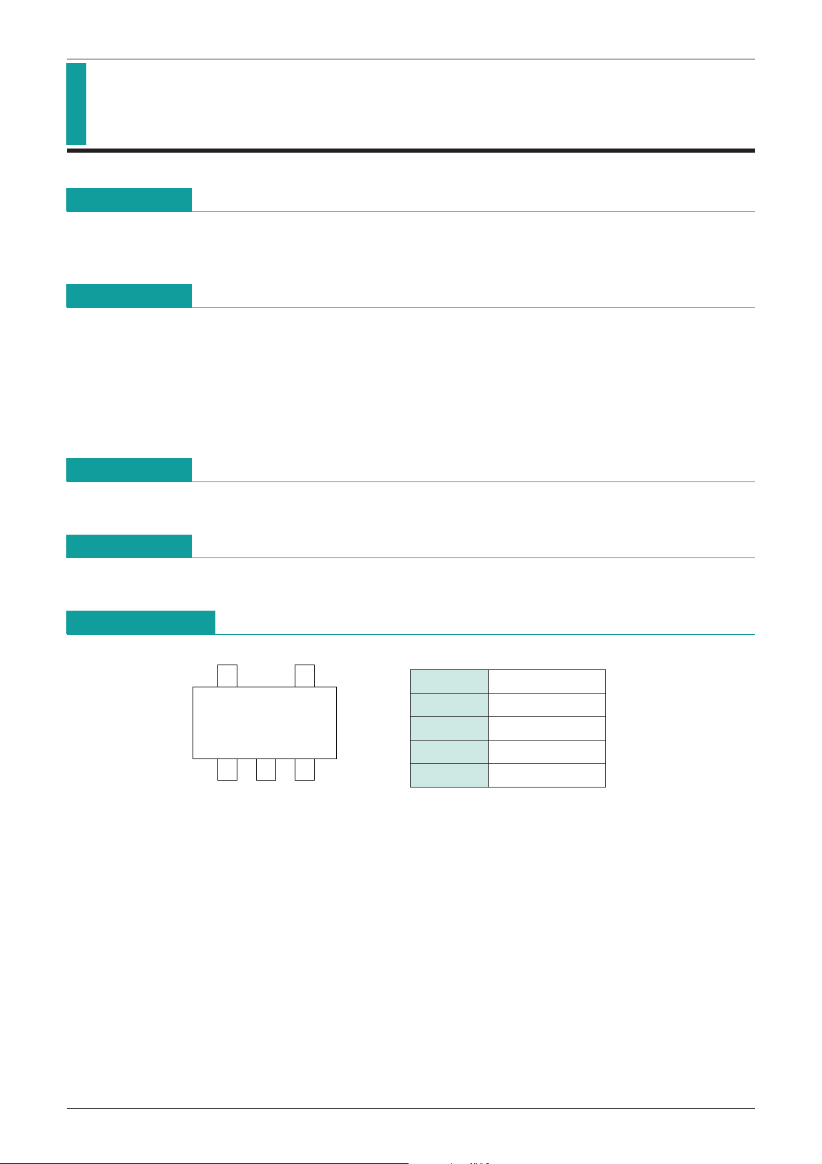
SOT-25
MITSUMI
Driver IC for Vibrators MM1426
Driver IC for Vibrators
Monolithic IC MM1426
Outline
This IC was developed as a driver for vibrator motors, and has an output voltage set at 1.3V.
The input voltage is monitored, and if a constant voltage is not input the output is turned off.
Features
1. Compact package for small mounting area.
2.
In addition to output control through the input voltage, the IC can be turned on and off through the CONT pin.
3. Good ripple rejection.
4. Output currents of up to 150mA.
5. Operating voltage of up to 12V.
6. Output voltage is available in 0.1V steps from 1.2V to 2.0V.
Package
SOT-25A
Applications
Cellular phones, PHS, game, pagers.
Pin Assignment
1 CONT
2 GND
3 N.C
4 V
5 VIN
OUT
Page 2
MITSUMI
MITSUMI
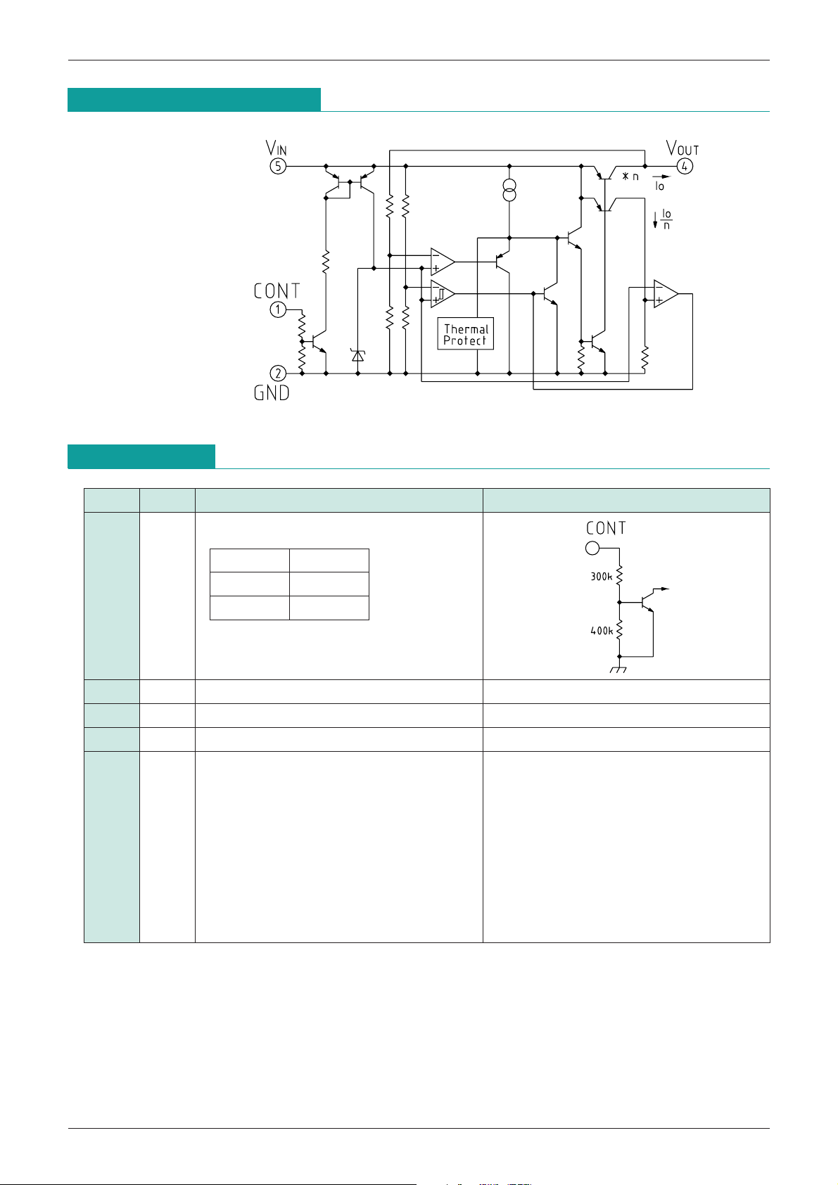
Equivalent Circuit Diagram
Driver IC for Vibrators MM1426
Pin Description
Pin No.
Pin name
Functions
1 CONT Output voltage on/off-control pin
VCONT Output
L OFF
HON
Connect cont-terminal with V
when it is not used.
2 GND GND pin
3 N.C
4 V
5 V
OUT Regulator Output pin
IN Voltage-supply input pin
Output voltage is not output when input voltage
is less than input voltage detection value.
Note that consumption current flows even
when output voltage is OFF due to input
Equivalent circuit diagram
IN,
voltage detection. Turn output OFF with the
CONT pin in order to suppress consumption
current completely.
Page 3

MITSUMI
MITSUMI
Absolute Maximum Ratings
Item Symbol Ratings Unit
Driver IC for Vibrators MM1426
Operating temperature T
Storage temperature T
Supply voltage V
Output current I
Power dissipation Pd 150 (Alone) mW
Recommended Operating Conditions
Item Symbol Ratings Unit
Operating temperature T
Output current I
Operating voltage V
Electrical Characteristics
Item Symbol Measurement conditions Min. Typ. Max. Unit
(Except where noted otherwise, Ta=25°C)
OPR
STG
CC
OUT 200 mA
OPR
OP 0~150 mA
OP 1.8~12 V
-
20~+75 °C
-
40~+125 °C
-
0.3~+12 V
-
20~75 °C
Output voltage Vo V
No-Load input current Iccq1 V
Input current 1 (OFF) Iccq2 V
Input current 2 (OFF) Iccq3 V
Line regulation V1 V
Load regulation V2 V
IN=3.5V Io=30mA
IN=3.5V Io=0mA 120 240 µA
IN=1.8V VCONT=1.6V 80 160 µA
IN=3.5V VCONT=0V 0.1 µA
IN=3V~5V Io=30mA 10 20 mV
IN=3.5V Io=0~100mA 30 60 mV
-
3% VO +3% V
Tj=-20~+75°C VIN=3.5V
Vo temperature coefficient
Vo/ T
100
Io=30mA
V
Ripple rejection RR
V
IN low detector voltage VSLVIN=H L Io=30mA 2.0 2.1 2.2 V
V
IN low detector voltage
VSL/ T
Tj=-20~+75°C VIN=H L Io=30mA 200
IN=3.5V f=120Hz
RIPPLE=1VP-P, Io=30mA
V
55 70 dB
temperature coefficient
V
IN high detector voltage VSHVIN=L H Io=30mA 2.6 2.8 V
High threshold voltage Vonh V
Cont terminal current I
ON VCONT=1.6V 5 10 µA
High threshold voltage H 1.6
Low threshold voltage L
IN=H L, L H 500 mV
VIN+0.3
-
0.3 0.4 V
ppm/°C
ppm/°C
V
Page 4

MITSUMI
2.6V
2.1V
0V
1.3V
0V
H
L
VIN
CONT
V
OUT
MITSUMI
Measuring Circuit
Application Circuits
Driver IC for Vibrators MM1426
NOTE 1 : This regulator is not internally compensated and thus requires an external output-capacitor (C
stability.
Timing Chart
OUT
) for
Page 5

MITSUMI
Output current (mA)
60
40
20
-
20
-
40
-
60
0
0 20 40 60 80 100 120 140
Load regulation (mV)
VIN (V)
10
5
-
5
-
10
0
4 6 8 10 12
Line regulation (mV)
Output current (mA)
1.5
1.25
0.75
0.5
0.25
0
1
0 100 200 300
Output voltage (V)
Temperature (°C)
800
700
500
400
300
200
100
0
600
0 25 50 75 100 125
Alone
On Board
57x31x0.8mm
Allowable loss (mW)
Temperature (°C)
2
1.75
1.25
1
0.75
0.5
0.25
0
1.5
25 75 125 175
Output voltage (V)
MITSUMI
Characteristics
Load regulation Line regulation
Current limit Thermal shutdown
Driver IC for Vibrators MM1426
Allowable loss
 Loading...