

Page 1
MITSUMI
Regulator+Reset IC MM1482
Regulator+Reset IC
Monolithic IC MM1482
Outline
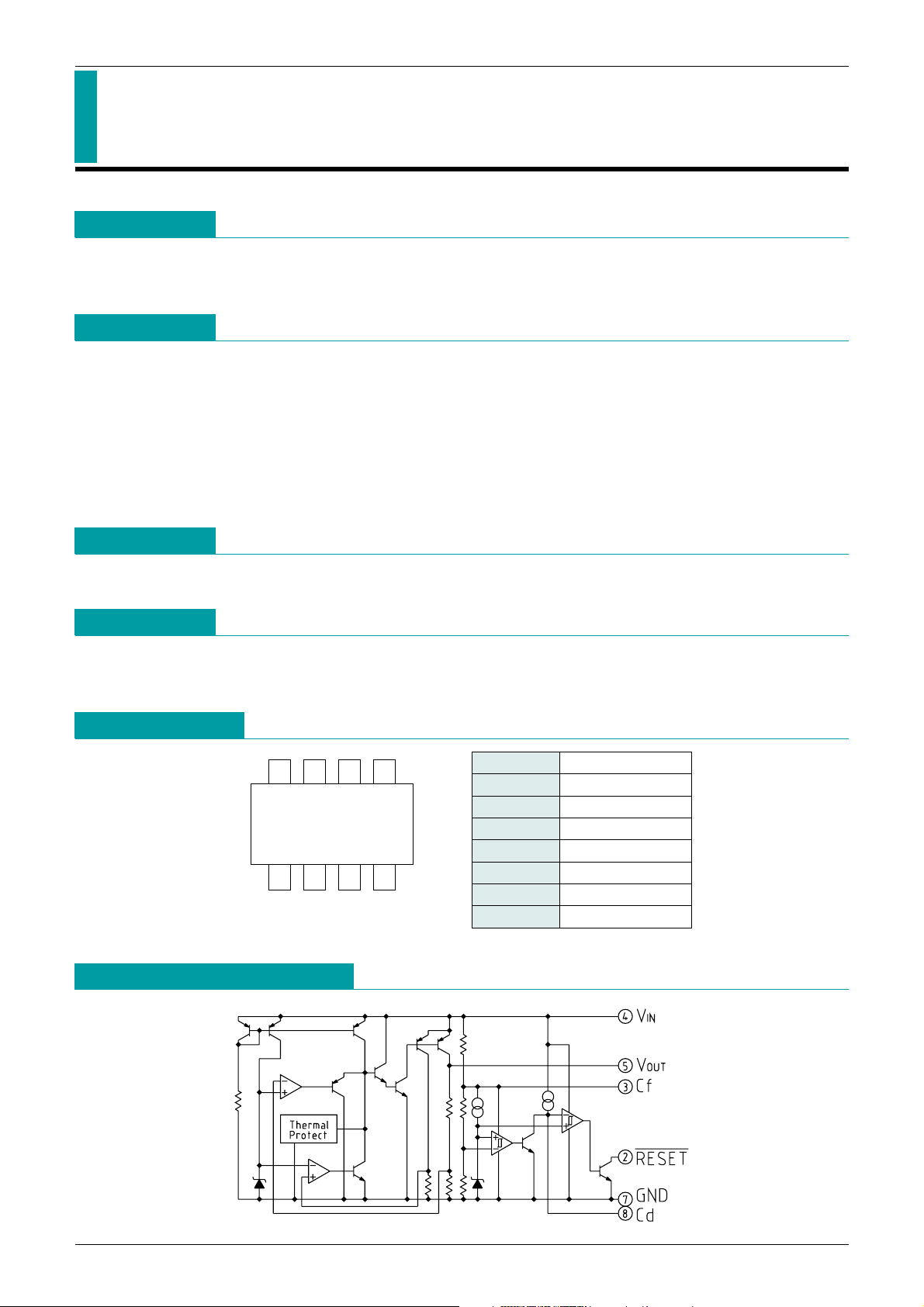
This IC, developed for use in CD-ROM drives, combines a 3V regulator adapted to low power consumption
with a much-sought reset function (regulator input monitoring), with internal delay circuit, set to detect 4.2V.
Features
1. Large output current 300mA max.
2. High ripple rejection rate 80dB typ.
3. Internal thermal shutdown circuit.
4. Internal current-limiting circuit.
5. Adjustment-free reset detection voltage 4.2V typ.
6. Easy to set delay time from voltage detection to reset release.
7. Operating temperature range and ripple elimination rate are available separately for 3 ranks.
Package
SOP-8D
Applications
Pin Assignment
Equivalent Circuit Diagram
1. CD-ROM drive
2. Optical disc drivers
1423
76
85
SOP-8D
(TOP VIEW)
MITSUMI
1 N. C
2 RESET
---------------------------------------------------------------------
3 Cf
4 V
IN
5 VOUT
6 N. C
7 GND
8 Cd
Page 2
MITSUMI
Regulator+Reset IC MM1482
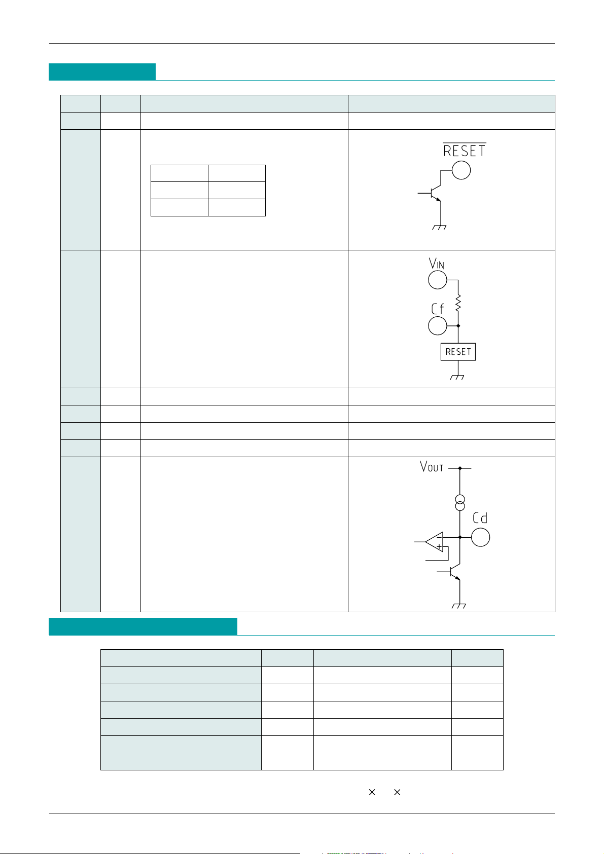
Pin Description
Absolute Maximum Ratings
MITSUMI
Pin No.
Pin name
Functions Equivalent circuit diagram
1 N. C
2 RESET
---------------------------------------------------------------------
VIN pin voltage detection output
RESET
---------------------------------------------------------------------
pin logic
3 Cf Ripple-filter pin (RESET)
Please connect a capacitor between Cf-GND
to reject ripple voltage of V
IN for RESET. It
become C-R low-pass filter. Internal
impedance of Cf is typically 14kΩ.
4 V
IN Voltage supply input pin
5 V
OUT Regulator Output pin
6 N. C
7 GND GND pin
8 Cd Delay time capacitor pin
t
PLH=100000·C
t
PLH: transmission delay time [s]
C: capacitor value [F]
__
RESET
V
IN<VS L
V
IN>VS H
Item Symbol Ratings Unit
Operating temperature
*
1 TOPR
-
30~+85 °C
Storage temperature T
STG
-
40~+125 °C
Supply voltage V
IN
-
0.3~+10 V
Output current I
OUT 400 mA
Power dissipation Pd
400(Alone)
*
mW
950(With board mounted)
*
2
Note1: *1 Rank B: -20 ~+80°C ; Rank A: -30 ~ +85°C
Note2:
*
2 When mounted on a (Copper foil area 80% 192 142 1tmm glass epoxy board.
RESET pin output delay time can be set by
the capacitance connected to the Cd pin.
Page 3
Item Symbol Measurement conditions Min. Typ. Max. Unit
No-Load Input Current Iccgl
V
IN=5V IOUT=0mA C rank 2.2 4 mA
A, B rank 3.0 6.0 mA
Regulator
Output Voltage V
OUT VIN=5V IOUT =30mA 3.23 3.30 3.37 V
Input-Output differential Voltage
ViO VIN=3.2V IOUT=150mA 0.15 0.3 V
Line Regulation V1 V
IN=4.4V~5.5V IOUT=30mA 0.05 5 mV
Load Regulation V2 V
IN=5V IOUT=0mA~300mA 20 120 mV
V
OUT
Temperature Coefficient *1
V
OUT
/ T
Tj=-20~+80°C
V
IN=5V IOUT=30mA
100
ppm/°C
VIN=5V f=120Hz VRIPPLE=1VP
-
P
Ripple Rejection *1 RR IOUT=30mA C rank
50 80 dB
A, B rank 50 90 dB
V
IN=5V, f=20~80kHz
Output Noise Voltage
*
1 Vn IOUT=30mA C rank
60 120
µVrms
A, B rank 40 120
µVrms
Reset
Detecting Voltage Vs V
IN=H L 4.11 4.20 4.29 V
Vs temperature Coefficient *1
Vs/ T Tj=20~80°C 100
ppm/°C
Hysteresis Voltage Vs VIN=H L H 100 200 mV
Low-Level Output Voltage V
OL VIN=3.9V RL=4.7k 100 200 mV
Output Leakage Current I
OH VIN=5V ±0.1 µA
Output Current when ON 1 I
OL VIN=3.9V, RL=0 5 mA
Output Current when ON 2 *1
IOL VIN=3.9V, RL=0 Ta=-20~+80°C 3 mA
"H"Transmission Delay Time *1
tPLH Cd Pin open 30 90 µs
Reset Delay Time
*
1 tPLH1 VIN=4V 5V, Cd=0.1µF 5 10 20 ms
"L"Transmission Delay Time *1
t
PHL Cd pin open 30 90 µs
Threshold Operating Voltage V
OPL VOL=0.4V 0.65 0.85 V
Cf terminal impedance RCF VIN=5V 14 kΩ
MITSUMI
Regulator+Reset IC MM1482
MITSUMI
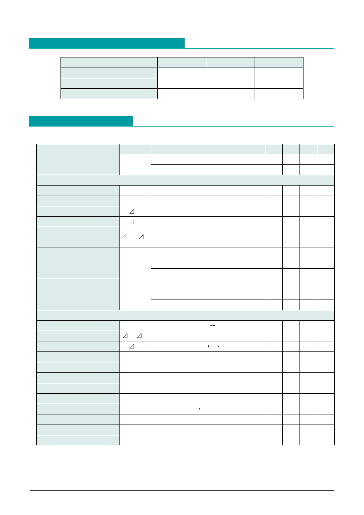
Electrical Characteristics
(Typical model 1482C) (Except where noted otherwise, Ta=25°C, V
CONT
=1.6V)
(Except where noted otherwise, resistance unit is Ω)
Recommended Operating Conditions
(Typical model MM1482C) (Except where noted otherwise, Ta=25°C)
Item Symbol Ratings Unit
Operating temperature T
OP
-
20~+80 °C
Output current I
OP 0~300 mA
Operating voltage V
OP 0~10 V
Note 1: design guaranteed
Note1: *1 Rank B: -20 ~+80°C ; Rank A: -30 ~ +85°C
Page 4
MITSUMI
Regulator+Reset IC MM1482
MITSUMI
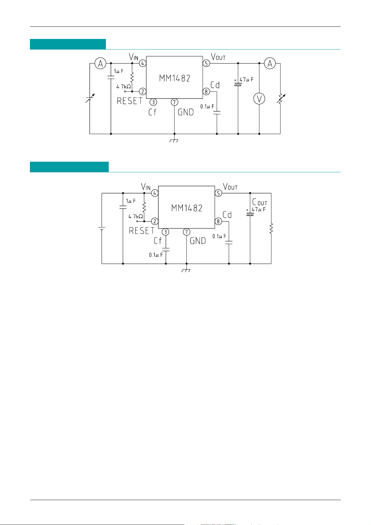
Application Circuit
Note 1 : This regulator is not internally compensated and thus requires an external output-capacitor (C
OUT
) for
stability.
Note 2 : Please be careful with regard to set wiring and temperature-related capacitor changes that may cause
oscillation.
Measuring Circuit
Page 5
MITSUMI
Regulator+Reset IC MM1482
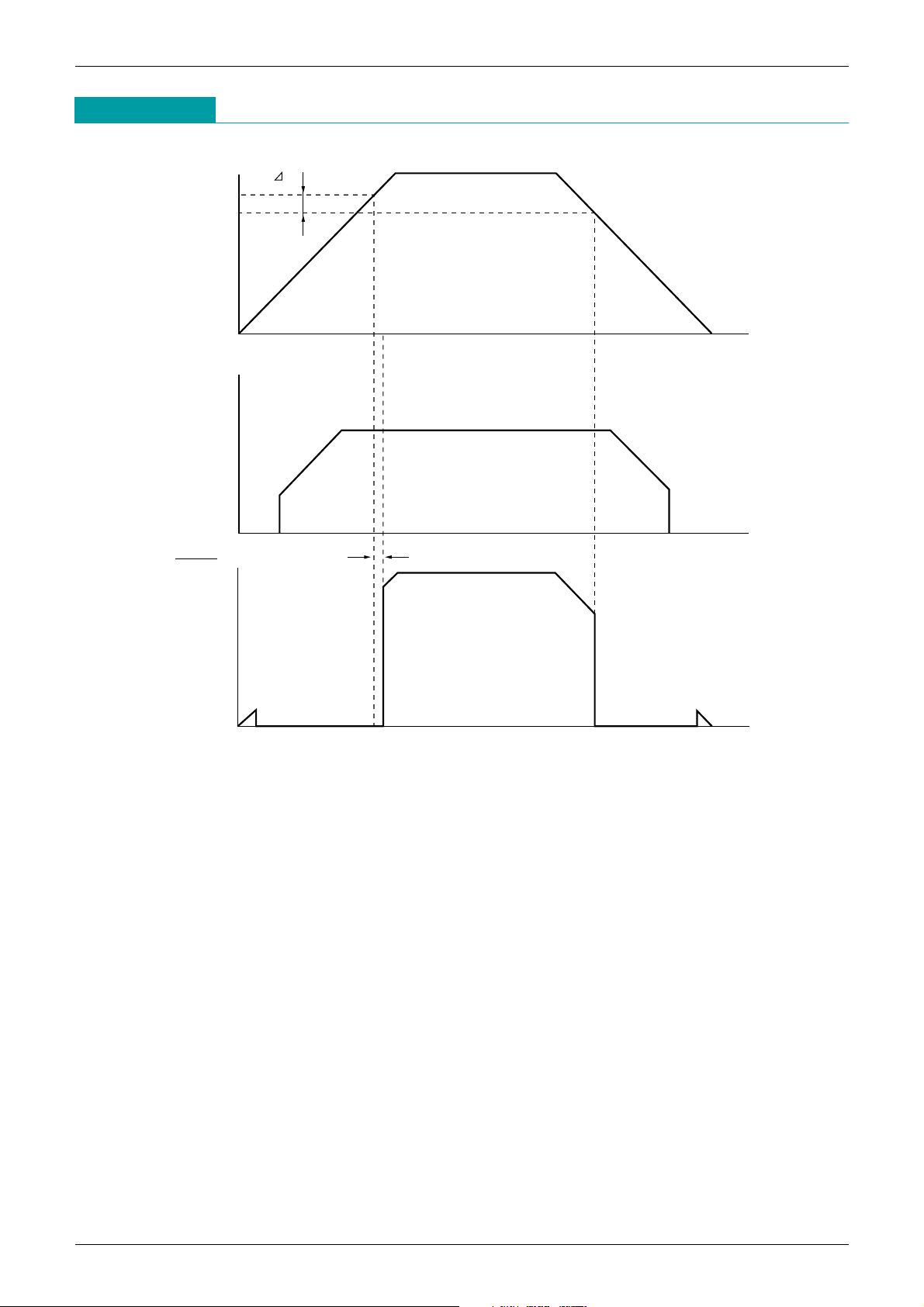
Timing Chart
tPLH1
Vs
VIN.
5V
Vs
0V
VOUT
5V
0V
5V
0V
RESET
Page 6
MITSUMI
Regulator+Reset IC MM1482
MITSUMI
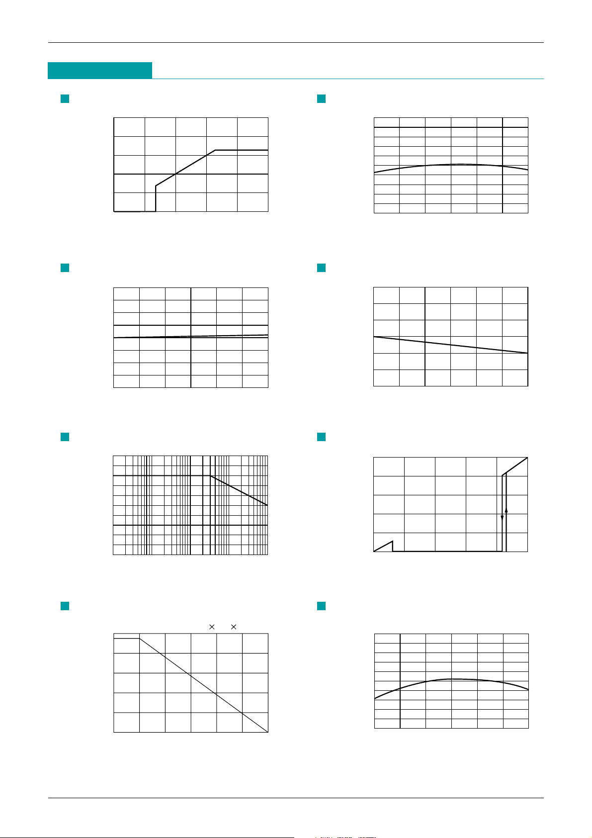
Characteristics
(Typical model MM1482C)
Regulator Output
Input voltage(V)
Output voltage (V)
12345
0
1
2
3
4
5
Output voltage vs temperature
Temperature (°C)
Output voltage (V)
-
25 0 25 50 75 100 125
3.2
3.22
3.24
3.26
3.28
3.3
3.32
3.34
3.36
3.38
3.4
Line regulation
Input voltage (V)
Line regulation (mV)
45678910
-
20
-
15
-
10
-
5
0
5
10
15
20
Load regulation
Output current (mA)
Load regulation (mV)
0 50 100 150 200 250 300
-
30
-
20
-
10
0
10
20
30
Ripple rejection
Frequency (Hz)
Rpple rejection (dB)
10
0
10
20
30
40
50
60
70
80
90
100
100 1000 10000 100000
Power Dissipation
Temperature (°C)
Power Dissipation (mV)
On board 192 142 1.2tmm
0 25 50 75 100 125 150
0
200
400
600
800
1000
Detecting voltage vs temperature
Temperature (°C)
Output voltage (V)
-
25 0 25 50 75 100 125
4.1
4.12
4.14
4.16
4.18
4.2
4.22
4.24
4.26
4.28
4.3
Reset Output
Input voltage(V)
Output voltage (V)
12345
0
1
2
3
4
5
 Loading...