

Page 1

MITSUMI
Secondary Control for Energy-Saving AC Adaptor MM1548
Secondary Control for Energy-Saving AC Adaptor
Monolithic IC MM1548
Outline
This IC is secondary control on AC adaptors that have energy-saving mode. The energy-saving mode
function operates when charging is completed or when the set is unplugged, thus greatly reducing AC
adaptor power consumption.
When a set is connected, normal mode automatically starts and charging starts.
Compared to the conventional MM1529, this IC is smaller and has fewer external components.
Features
1. Automatic switching between energy-saving mode and normal mode
2. Current consumption (energy-saving mode) 60µA
3. Current consumption (normal mode) 1.5mA
4. Uses one photocoupler to control oscillator primary side.
5. One photocoupler is used to control rated voltage and rated current and switching between energy-saving
and normal modes.
Package
SOT-26
MITSUMI
Pin Assignment
1 6
2 5
3 4
SOT-26
1 OUT 4 PO1
2 CNT 5 GND
3 V
CC 6 CS
Page 2

MITSUMI
Secondary Control for Energy-Saving AC Adaptor MM1548
MITSUMI
Block Diagram
GND
5
CS
6
PO1
4
VCC
3
CNT
2
OUT
1
COUT
ROS1
ROS2
RCS
Constant current detection resistor
(CS=34mV)
Reference voltage decrease (drop)
Constant current control
(CS=114.4mV)
Constant voltage control
(V
CC=5.1V)
Load detection(voltage)
(V
CC=3.5V)
Over voltage
detection
(7V)
5k
Load detection(current)
(115mV 200mV)
Input/output difference control
(VCC-OUT=200mV)
Voltage bufferPhotocoupler-turn-off
Primary-side switching
control
RLS
Load detection resistor
RLB
VCC
1.25V
Reference voltage
PC1
RL1
transformer secondary side
VCC=4.6V
Page 3
MITSUMI
Secondary Control for Energy-Saving AC Adaptor MM1548
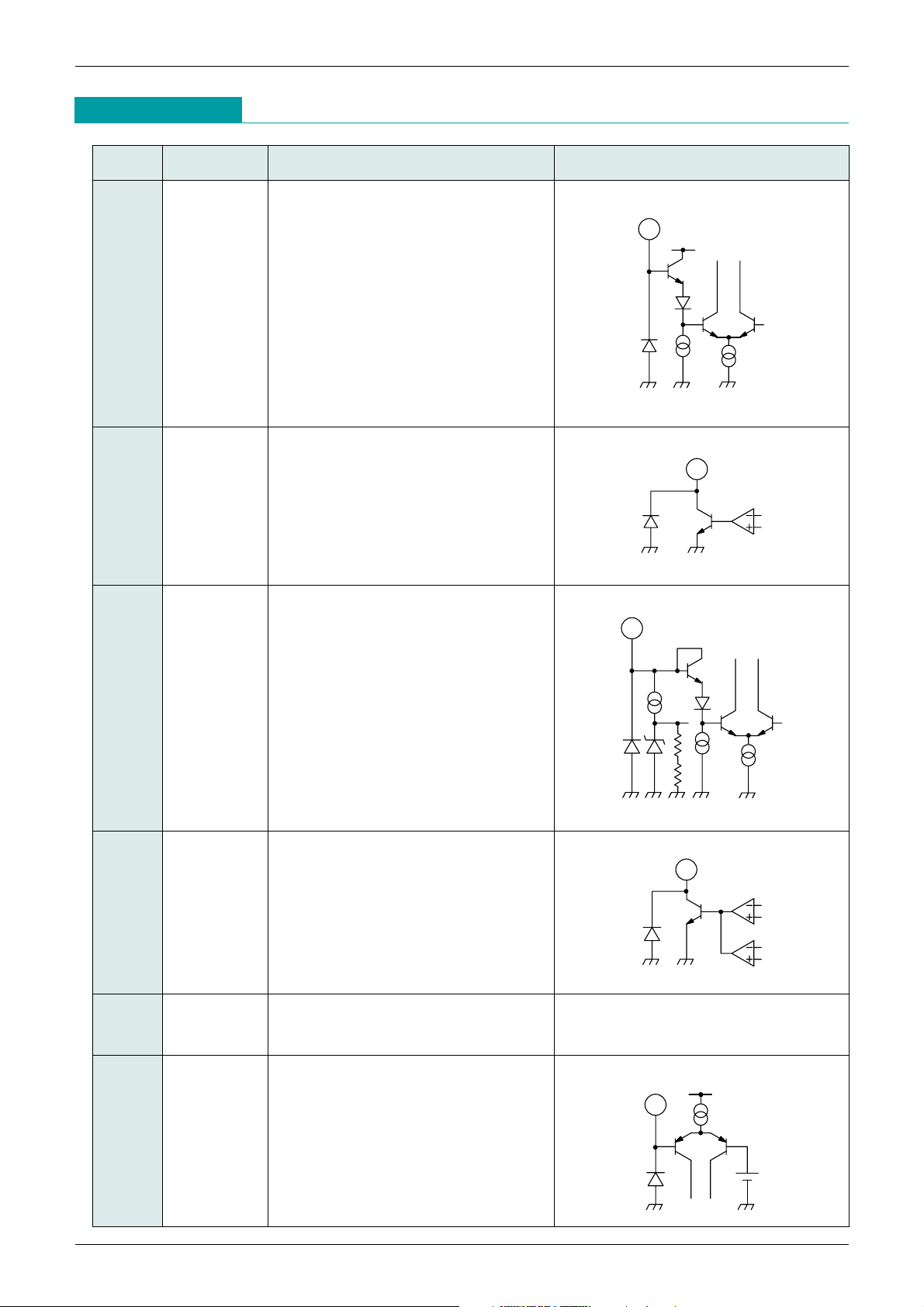
Pin Description
Pin No. Pin Name Function Internal equivalent circuit
1 OUT
Output (+) pin.
Connect Registor for load detection
between V
CC pin, and connect collector
of PNP power transistor.
VCC
1
2
1.25V
3
4
6
VCC
2 CNT PNP power transistor control pin.
Connect base of PNP power transistor.
4 PO1 Photo diode drive pin of photocoupler
for constant-current and constant-
voltage control.
Connect to cathode of diode.
5 GND Ground pin of this IC.
6 CS Overcurrent detection pin.
This pin doubles as output- pin.
Connect Resistor for overcurrent
detection between GND pin.
3 V
CC (+) power supply pin.
This pin doubles load detection pin.
Connect load detection resistor
between OUT pin, and connect emitter
of PNP power transistor.
Page 4

MITSUMI
Secondary Control for Energy-Saving AC Adaptor MM1548
Absolute Maximum Ratings
(Ta=25°C)
Recommended Operating Conditions
Electrical Characteristics
(unless otherwise specified, Ta=+25°C, Vcc=4.9V)
Item Symbol Ratings Unit
Storage temperature T
STG –40~+125 °C
Operating temperature T
OPR –30~+85 °C
Supply voltage V
CC max. –0.3~+18 V
Allowable loss Pd 150 (alone) mW
Item Symbol Ratings Unit
Operating temperature T
OPR –30~+85 °C
Supply voltage V
OP +2.5~+12 V
Item Symbol Test Conditions Min. Typ. Max. Unit.
Current consumption1(energy saving mode)
I
CC1 VCC=4.4V, VOUT=4.4V, VCS=0V 60 110 µA
Current consumption2(normal mode)
ICC2 VCC=5.3V, VOUT=5.0V, VCS=0V 1.5 3.0 mA
Voltage control section
Output inversion voltage V
O IIN=5mA, VOUT=VCC–0.3V, VCS=0V 4.99 5.10 5.21 V
OUT input sink current I
OUT VCC=4.9V, VOUT=4.9V, VCS=0V 25 150 nA
PO1 output sink current 1 I
PO1 VCC=5.3V, VOUT=5.0V, VCS=0V VPO1=0.5V 5 17 mA
Constant current control
Output inversion voltage 1
V
CS1
VCC=4.9V, R
CS1
=1kΩ, V
OUT
=4.6V, R
CS2
=40kΩ, IIN=5mA
111.2 114.4 117.6 mV
(Constant current control)
Output inversion voltage 2
V
CS2
VCC=2.0V, R
CS1
=1kΩ, V
OUT
=0V, R
CS2
=40kΩ, IIN=5mA
22 34 mV
(Constant current control drop)
CS input source current ICS VCC=4.9V, VOUT=4.6V, VCS=0.1V 5 100 nA
Power supply voltage rejection ratio
PSRR2
VCC=3.7V 4.4V, VCS=V
CS1
–10mV, RL1=5kΩ
60 70 dB
PO1 output sink current 2 I
PO2 VCC=4.9V, VOUT=4.6V, VCS=0.2V, VPO1=0.5V 5 17 mA
Input-output difference control
Input-output difference control voltage
V
LS VCC=5.1V, RLS=4.7kΩ, RLB=100Ω, RO=5kΩ 140 200 260 mV
CNT output sink current I
CNT VCC=5.1V, VOUT=4.8V, VCS=0V, VCNT=0.8V 5 30 mA
Load detection
Load detection voltage V
LSP1
VCC=4.9V, RL1=47kΩ, V
OUT
=4.9V L, VCS=0V
170 200 230 mV
Energy saving detection voltage
V
LSP2
VCC=4.9V, RL1=47kΩ, V
OUT
=L 4.9V, VCS=0V
85 115 145 mV
(load detection release voltage)
3.5V undervoltage detection VOL1 VCC=H L, RL1=10kΩ, VOUT=VCC, VCS=0V 3.4 3.5 3.6 V
3.5V undervoltage detection hysteresis
VOL1H VCC=L H, RL1=10kΩ, VOUT=VCC, VCS=0V 350 mV
4.6V undervoltage detection V
OL2 VCC=H L, RL1=47kΩ, VOUT=VCC, VCS=0V 4.47 4.60 4.73 V
PO1 output sink current 3 I
PO3 VCC=4.9V, VOUT=4.6V, VCS=0V, VPO2=1.0V 100 200 400 µA
PO1 output source current I
PO4 VCC=4.9V, VOUT=4.9V, VCS=0V, VPO2=4.6V 1.0 5.0 mA
Constant current mode selection
2pin(CNT pin) disable voltage V
CNTO
VCC=H L, V
CNT
=0.8V, V
OUT=VCC
–0.3V, VCS=0V, I
CNT
< 1mA
2.4 V
Constant current mode selection threshold
VCSS
VCC=4.9V, R
CS1
=1kΩ, V
OUT
=4.6V, R
CS2
=20kΩ, IIN=5mA, V
CS
< V
CS
min.
0.6 V
(between V
CC and OUT)
Page 5
MITSUMI
Secondary Control for Energy-Saving AC Adaptor MM1548
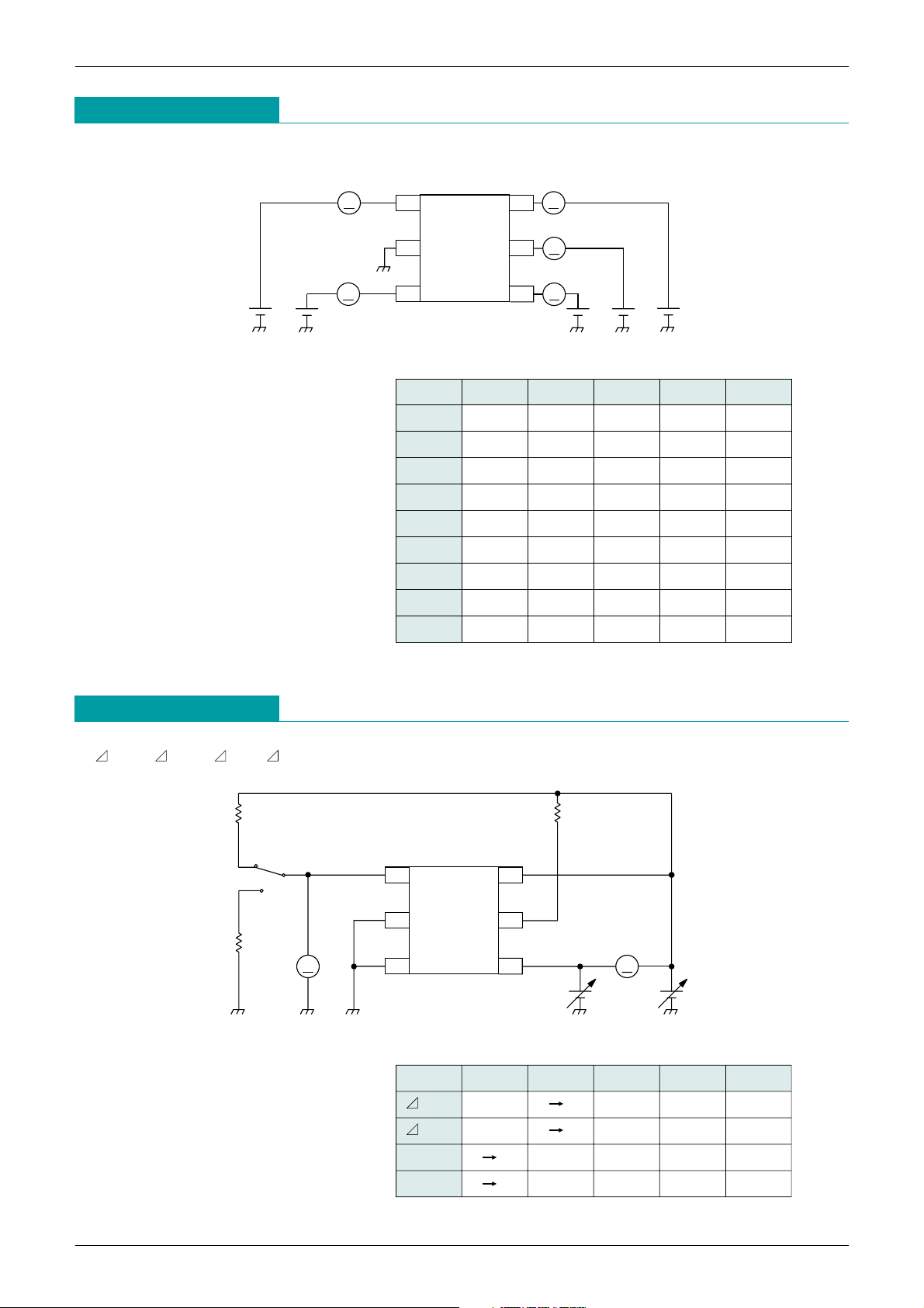
Measuring Circuit 1
ICC1, ICC2, IOUT, ICS, IPO1, IPO2, IPO3, IPO4, ICNT
VLSP1, VLSP2, VOL1, VOL2
Measuring Circuit 2
4 PO1 VCC
GND CNT
CS OUT
3
5 2
6 1
A
VCCVPO1
A
A
VCNTVOUT
I CNT
I CNT
I CC
A
I PO1
VCS
A
I CS
4 PO1 VCC
GND CNT
CS OUT
3
5 2
6 1
VV
VCC
V
R
L3RL1
R
L2
OUT
VCC VOUT VCS VPO1 VCNT
ICC1 4.4V 4.4V 0.0V OPEN OPEN
I
CC2 5.3V 5.0V 0.0V OPEN OPEN
I
OUT 4.9V 4.9V 0.0V OPEN OPEN
I
CS 4.9V 4.9V 0.1V OPEN OPEN
I
PO1 5.3V 5.0V 0.0V 0.5V OPEN
I
PO2 4.9V 4.6V 0.2V 0.5V OPEN
I
PO3 4.9V 4.6V 0.0V 1.0V OPEN
I
PO4
4.9V 4.9V 0.0V 4.6V OPEN
I
CNT 5.1V 4.8V 0.0V OPEN 0.8V
VCC VOUT VCS VPO1 VCNT
VLSP1 4.9V 4.9 4.6V 0V
RL1=47kΩ RL3=10kΩ
VLSP1 4.9V 4.6 4.9V 0V
RL1=47kΩ RL3=10kΩ
VOL1 3.7 3.3V VCC 0V
RL1=10kΩ
OPEN
V
OL2 4.8 4.4V VCC 0V
RL2=47kΩ
OPEN
Page 6
MITSUMI
Secondary Control for Energy-Saving AC Adaptor MM1548
4 PO1 VCC
GND CNT
CS OUT
3
5 2
6 1
VCC
C
100µF
RO
5kΩ
R
LS
4.7k
100Ω
OUT
V
2SB1424
R
LB
RL1
5kΩ
100Ω
10kΩ
4 PO1 VCC
GND CNT
CS OUT
3
5 2
6 1
VCS
V
V
3.7V 4.4V
CC
VOUT
VCC–0.3V
4 PO1 VCC
GND CNT
CS OUT
3
5 2
6 1
VOUT
I in
5mA
V
4 PO1 VCC
GND CNT
CS OUT
3
5 2
6 1
VOUT
I in
5mA
VCC
RCS2
RCS1
V
VLS
PSRR2
V
O
VCS1, VCS2
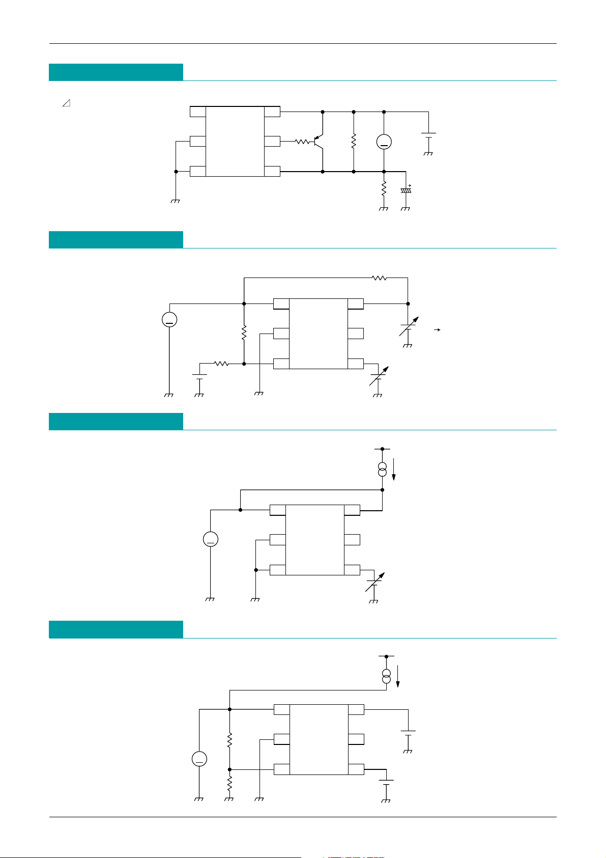
Measuring Circuit 3
Measuring Circuit 4
Measuring Circuit 5
Measuring Circuit 6
Page 7
MITSUMI
Secondary Control for Energy-Saving AC Adaptor MM1548
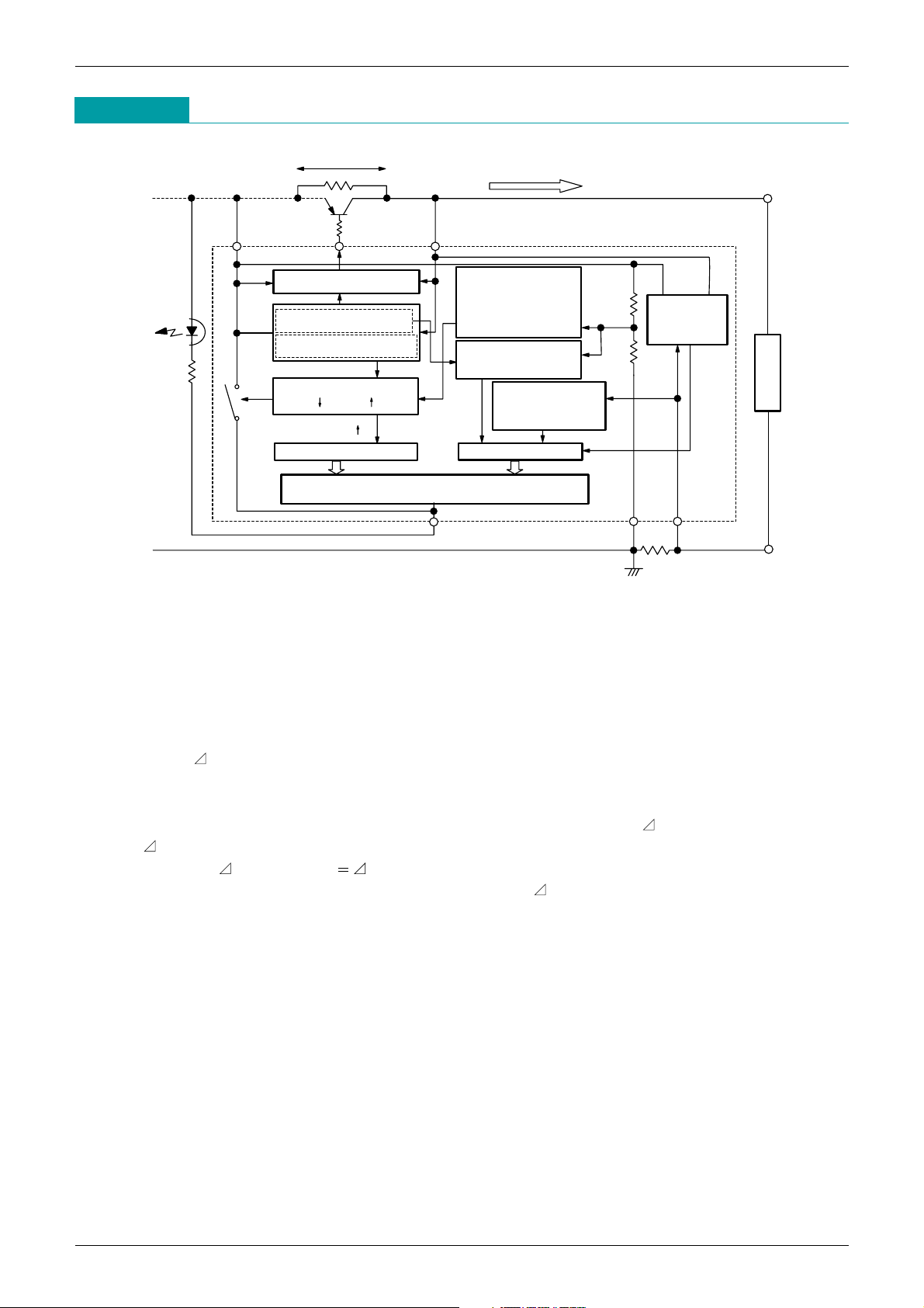
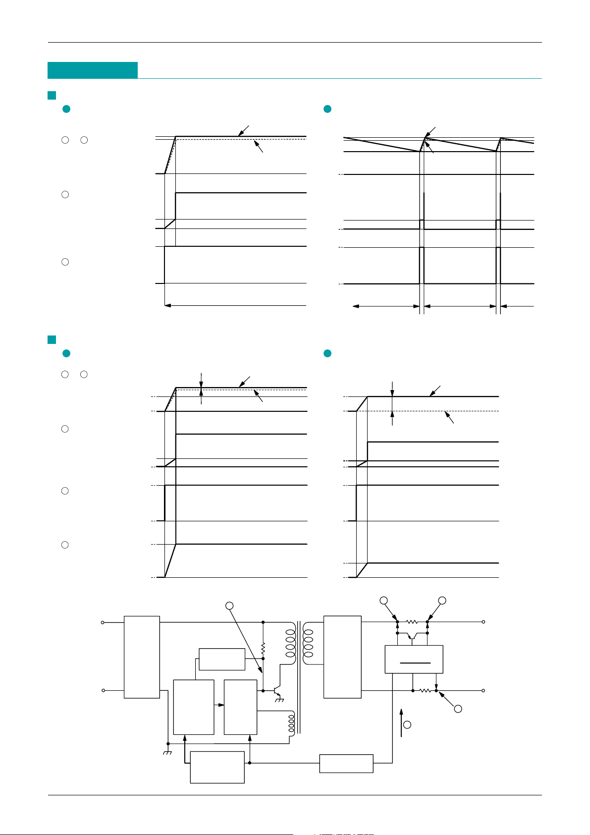
1. Operation of Blocks
1.1 Input/output difference control
In the normal mode that a load current is detected and the system supplies the load current through the
Supply Transistor (PNP type), MM1548 controls CNT current flowing into the base of Supply Transistor to
keep the differential voltage between V
CC and OUT (Vce of Supply Transistor) at 200mV.
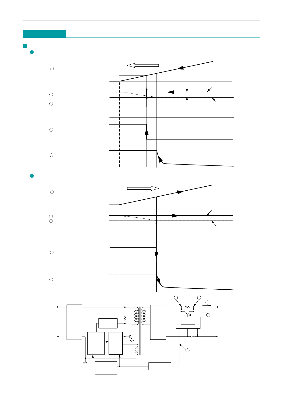
1.2 Load current detection and Energy saving current detection
When load current increases in energy saving mode and the differential voltage between V
CC and OUT
exceeds V
LSP1 (200mV), MM1548 changes to the normal mode, PO1 switches from open to low mode,
and the photocoupler PC1turns on. As a result, the system switches primary-side switching operation to
normal mode from disabled.
The switching voltage has following hysteresis if load current is increasing ( V
LSP1) or decreasing
( V
LSP2).
( hysteresis: V
LSP1 = 200mV < > VLSP2 = 115mV)
When the differential voltage between V
CC and OUT falls to VLSP2 (115mV), MM1548 changes to the
energy saving mode, and the photocoupler-turn-off circuit switches compulsory photocoupler current to
zero under the condition that load current is decreasing in normal mode and Vcc = 4.6V or more.
1.3 Voltage drop detection
When V
CC voltage falls to 4.6V in the energy saving mode, MM1548 stops the photocoupler-turn-off circuit
operation to save consumption current of MM1548.
When V
CC voltage falls to 3.5V in the energy saving mode, MM1548 changes to the normal mode.
As a result, Out voltage (output of secondary side) swings intermittent between 4.9V and 3.5V.
1.4 Constant current control
When load current is increasing in the normal mode, and the differential voltage between CS and GND
exceeds V
CS1(114.4mV typ.), PO1 switches from open to low mode, and the photocoupler PC1 turns on. As
a result, MM1548 changes to the CC(constant current) mode, and the load current is controlled that CS
voltage keeps V
CS1.
1.5 Constant voltage control
When MM1548 is in normal mode and isn't in constant current mode, it is in CV(constant voltage) mode,
and PO1 current is controlled that V
CC voltage keeps 5.1V (equal to internal 1.25V: REF voltage).
Voltage between VCC and OUT(200mV)
RLS
470Ω
R
LB
100Ω
Supply transistor
CNT
Load current
VCC
200mV
200mV
115mV
Energy saving mode Normal mode
Input/output difference control
Load current detection
Energy saving current detection
PO1 drivePO1 drive(Load 5kΩ)
Photocoupler PC1 control
PO1
OUT
PC1
Output
(
–)
GND
RCS
CS
0.22
Ω
Load
(+)
Voltage drop detection
(V=4.6V)
Voltage drop detection
(V
CC=3.5V)
Constant voltage control
(VCC=5.1V)
Constant current control
(CS=114.4mV)
(Io=520mA)
ROS1
ROS2
REF
Overvoltage
detection
(V
CC,
OUT=7V)
Energy saving mode control
(3.5V :ON, 5.1V :OFF)
Photocoupler-turn-off(4.6V )
Operation
Page 8
MITSUMI
Secondary Control for Energy-Saving AC Adaptor MM1548
1.6 Overvoltage detection
When V
CC voltage or OUT voltage exceeds 7V (overvoltage), overvoltage detection circuit turn on.
As a result, PO1 sink current is controlled to turn on the photocoupler PC1, and system is protected from
overvoltage.
This circuit also detects negative voltage applied CS pin, and when it is detected, PO1 current is turned off
for overvoltage protection.
2. Design principles for each mode
AC adaptor output is controlled by following 4 mode under usage with MM1548.
Switching of each control mode is explained as follow.
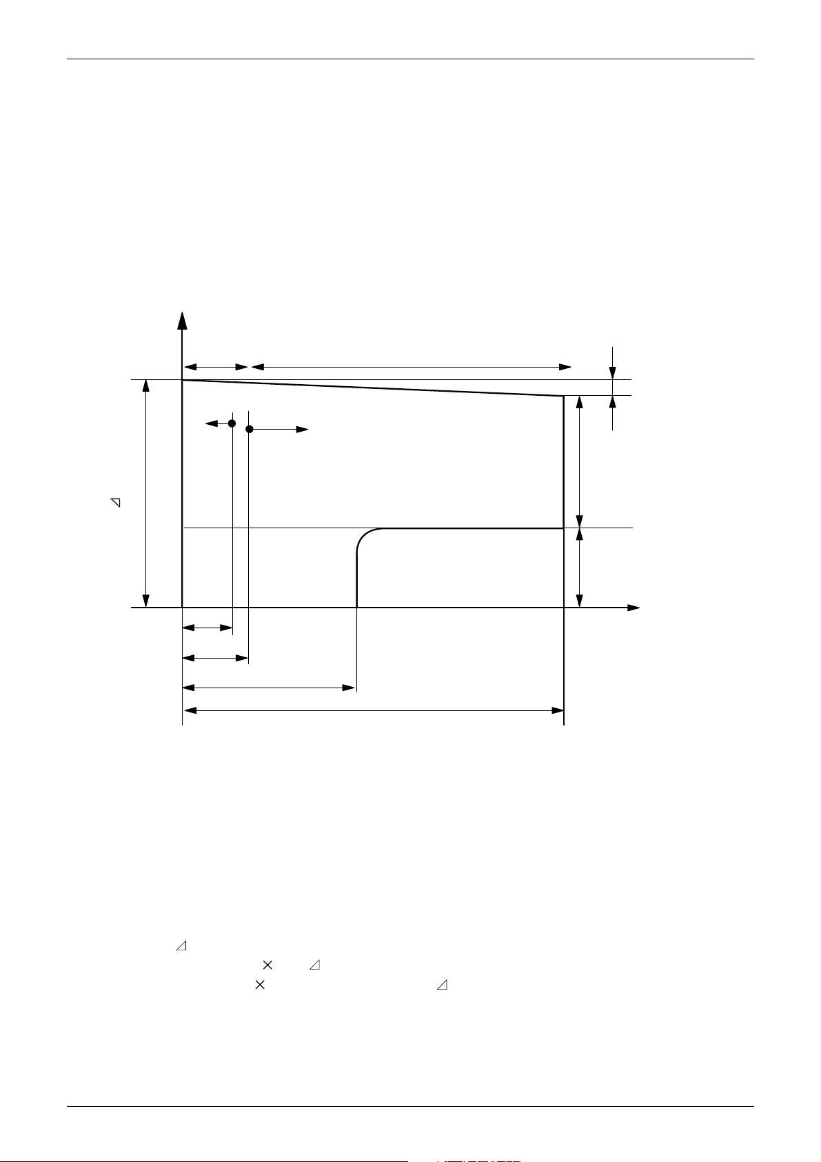
2.1 for Output voltage
In MM1548 series, the output voltage can't be adjusted by external resistor, because referential voltage
terminal (REF pin) for adjustment is build in the chip.
Instead of voltage adjustment, you can chose output voltage by select the rank of MM1548 series.
Output voltage is lower 0.2V (equal to in-out differential control voltage) than 5.1V(equal to the value set by
ROS1 and ROS2).
[Formula]
Output voltage
= Vo – VLS
= {1+(ROS1/ ROS2)} 1.25 – VLS (Vo = 5.1V)
= {1+(2460k/800k)} 1.25 – 0.2 ( VLS = 0.2V)
= 4.9V
[A]
C
V MODE
(PO1:Control)
CC MODE
(PO1:Control)
VCS(115mV typ.)
Energy saving mode
(PO1:Open)
Energy saving current detection (load detection release )
Load current detection
CC MODE
Drop curve
(PO1:Control)
114.4mV/RCS
(115mV/R
LS)
(200mV/R
LS)
34mV/RCS
Load current
Vo(5.1V typ.)– VLS(0.2V typ.)
Output voltage (between OUT and CS) [V]
Page 9
MITSUMI
Secondary Control for Energy-Saving AC Adaptor MM1548
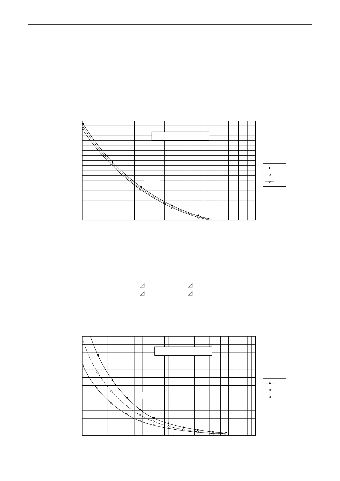
2.2 for Constant current detection (RCS adjust method)
Constant current value is set by RCS value as load detection resistor.
On the design, constant current operation changes when [load current] > 520[mA] in the case of 0.22Ω use.
[Formula]
[Constant current control] = V
CS1 / RCS (VCS1 = 114.4mV)
[Drop curve] = V
CS2 / RCS (VCS2 = 34mV)
200
300
400
500
600
700
800
900
1000
1100
1200
I= (VCS1) / RCS
RCS(constant current detection resistor) - constant current control value
constant current control value [mA]
RCS(constant current detection resistor) [Ω]
0.1 1.0
min.
typ.
max.
0.22Ω
2.3 Description of load detection and energy saving detection (RLS adjust method)
Load detection current and energy saving detection current is set by R
LS as load detection resistor.
On the design, each current changes when [current flows through R
LS] > 240µA, in the case of 470Ω use.
[Formula]
[Load detection current] = ( V
LSP1 / RLS) ( VLSP1 = 200mV)
[Energy saving detection current] = ( V
LSP2 / RLS) ( VLSP2 = 115mV)
0
100
200
300
400
500
600
700
800
900
1000
1100
1200
I= ( VLSP2) / RLS
RLS (Load detection resistor) - Energy saving detection current
Energy saving detection current [µA]
RLS (Load detection resistor) [kΩ]
0.1 101
min.
typ.
max.
470Ω
Page 10
MITSUMI
Secondary Control for Energy-Saving AC Adaptor MM1548
5.1V
4.9V
VCC
OUT
0V
0mA
ON
OFF
5.1V
4.9V
3.5V
VCC
OUT
0V
0mA
ON
OFF
VCC, OUT PIN
(secondary side output)
1
PO1 current
(load det. + constant
voltage control output)
3
Primary side switching
4
2
Normal mode
Normal mode
Energy saving mode Energy saving mode
Normal mode
Constant voltage control
Normal mode [Io>115mV / RLS]
Energy saving mode [Io<115mV / R
LS]
2V
OUT
0V
0mA
ON
114.4mV
0mV
200mV
OFF
2V
OUT
V
CC
0V
0mA
ON
0mV
34mV
over 0.6V
OFF
VCC, OUT PIN
(secondary side output)
1
PO1 current
(load det. + constant
voltage control output)
3
Primary side switching
4
CS terminal
(constant current
control input)
5
2
Constant current control
Normal control [VCC>2.0V]
Drop control [V
CC<2.0V]
AC input output
Delay circuit
Switching
interruption
control
Switching
circuit
Smoothing
circuit
MM1548
+
–
Signal detection
circuit
Photocoupler
RLS
V
CC CNT OUT
PO1 GND CS
RCS
4
1
2
3
5
Rectifying
circuit
Timing Chart
Page 11
MITSUMI
Secondary Control for Energy-Saving AC Adaptor MM1548
Timing Chart
1 VCC PIN
2 OUT PIN
3 PO1 PIN
4 CNT PIN
5.1V
4.9V
0V
Open
Open
115mV 200mV
VCC
OUT
Low(Load 5kΩ)
Control
0mA
5 Load current
Load detection current
(200mV/RLS)
Energy saving current
(115mV/RLS)
Load current decrease
5 Load current
1 V
CC PIN
2 OUT PIN
3 PO1 PIN
4 CNT PIN
Load current increase
Load detection current
(200mV/RLS)
Energy saving current
(115mV/RLS)
5.1V
4.9V
0V
Open
Open
200mV
VCC
OUT
Low(Load 5kΩ)
Control
0mA
Load current increase
AC input
Rectifying
circuit
Delay circuit
Switching
interruption
control
Switching
circuit
Smoothing
circuit
MM1548
Output
+
–
signal detection
circuit
Photocoupler
RLS
VCC CNT OUT
PO1 GND CS
RCS
4
3
5
21
Load / Energy-saving detection
Load current decrease
Page 12
MITSUMI
Secondary Control for Energy-Saving AC Adaptor MM1548
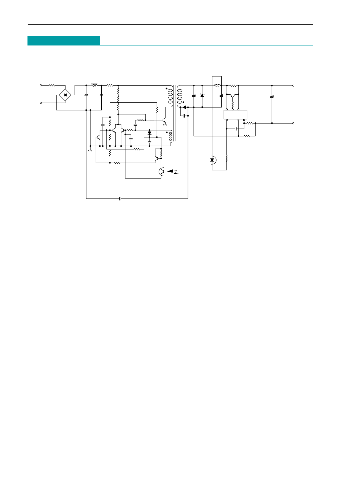
Application Circuit
INPUT
AC100V
OUTPUT
+
DC4.9V
520mA
–
PH1
10
R20
D1
L1 R1
6.8
C6
0.22
µ
C2
4.7
µ
470µ
220µ
220µ
0.22µ
4.7µ
0.1µ
C12
1M2.2M
3.3M
100k
R3270k
R4
R7
R8
C4
C5
1.5M
R5
C7
D4
C8
C9
R18
100
R11
10k
1000p
R13
10k
R2
Q2 Q3
Q4
R12
10k
470
R10
470
R9
4700p
C3
R14
100k
D2
Q6
Q1
D3
C13
0.0056
µ
L2 470
R15
Q5
470
R17
0.22
R16
C10
R19
10
VCCCNT OUT
PO1 GND CS
MM 1548
T1
C11
2200p
 Loading...