

Page 1
MITSUMI
1432
8567
VSOP-8B
MITSUMI
IC for Control of Lithium-ion Betteries Charging MM1438
IC for Control of Lithium-ion Betteries Charging
Monolithic IC MM1438
Outline
This IC is used to control charging of lithium-ion batteries consisting of a single cell. It is a modification of the
previous MM1332 charging-control IC, with improved charging voltage accuracy and a smaller package.
Features
1. Charging voltage accuracy (Ta=25°C) ±25mV/cell
2. Charging voltage accuracy (Ta=0 to 50°C) ±30mV/cell
3. Consumption current (charging on) 250µA typ.
4. Consumption current (charging off) 2µA typ.
5. Low-voltage detection 2.15V typ.
6. Leakage current between CEL and CS 1µA max.
Package
VSOP-8B
Applications
IC for control of lithium-ion batteries charging.
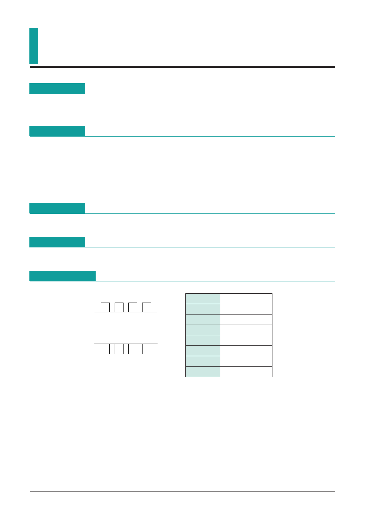
Pin Assignment
1 GND
2 LV
3 SW2
4 SW1
5 V
6 EXT
7 CEL
8 CS
CC
Page 2

MITSUMI
MITSUMI
Block Diagram
IC for Control of Lithium-ion Betteries Charging MM1438
Pin Description
Pin No. Pin name I/O
1 GND Input Ground pin
Low voltage detection circuit output pin
2 LV Output
ON with NPN-Tr open collector output at low voltage
Low voltage detection circuit ON/OFF control input pin
3 SW2 Input
SW2 = V
CC: OFF, SW2 = GND: ON
ON/OFF control input pin for the IC
4 SW1 Input
5 V
CC Input Power supply input pin
6 EXT Output
SW1 = V
Charging control output pin Controls external PNP-Tr to control charging.
CC: OFF, SW1 = GND: ON
Battery voltage input pin
7 CEL Input
Detects battery voltage and controls rated voltage to the prescribed voltage value.
Current detection pin
8 CS Input Detects current by drop in external resistor voltage and controls rated current.
Current value can be set at 0.1V/R1 typ.
Pin Description
Page 3

MITSUMI
IC for Control of Lithium-ion Betteries Charging MM1438
Absolute Maximum Ratings
(Ta=25°C)
Item Symbol Ratings Unit
Storage temperature T
Operating temperature T
Power supply voltage V
CFL pin input voltage V
CC max.
CEL max.
SW input voltage V
Allowable loss Pd 300 mW
Recommended Operating Conditions
Item Symbol Ratings Unit
Operating temperature T
Charging control operating voltage
Note: Operating voltage minimum value is during rated current control.
STG
OPR
SW
OPR
-
40~+125 °C
-
20~+70 °C
-
0.3~+18 V
-
0.3~+13 V
-
0.3~VCC+0.3 V
-
20~+70 °C
VOPR 2.5~+17 V
Electrical Characteristics
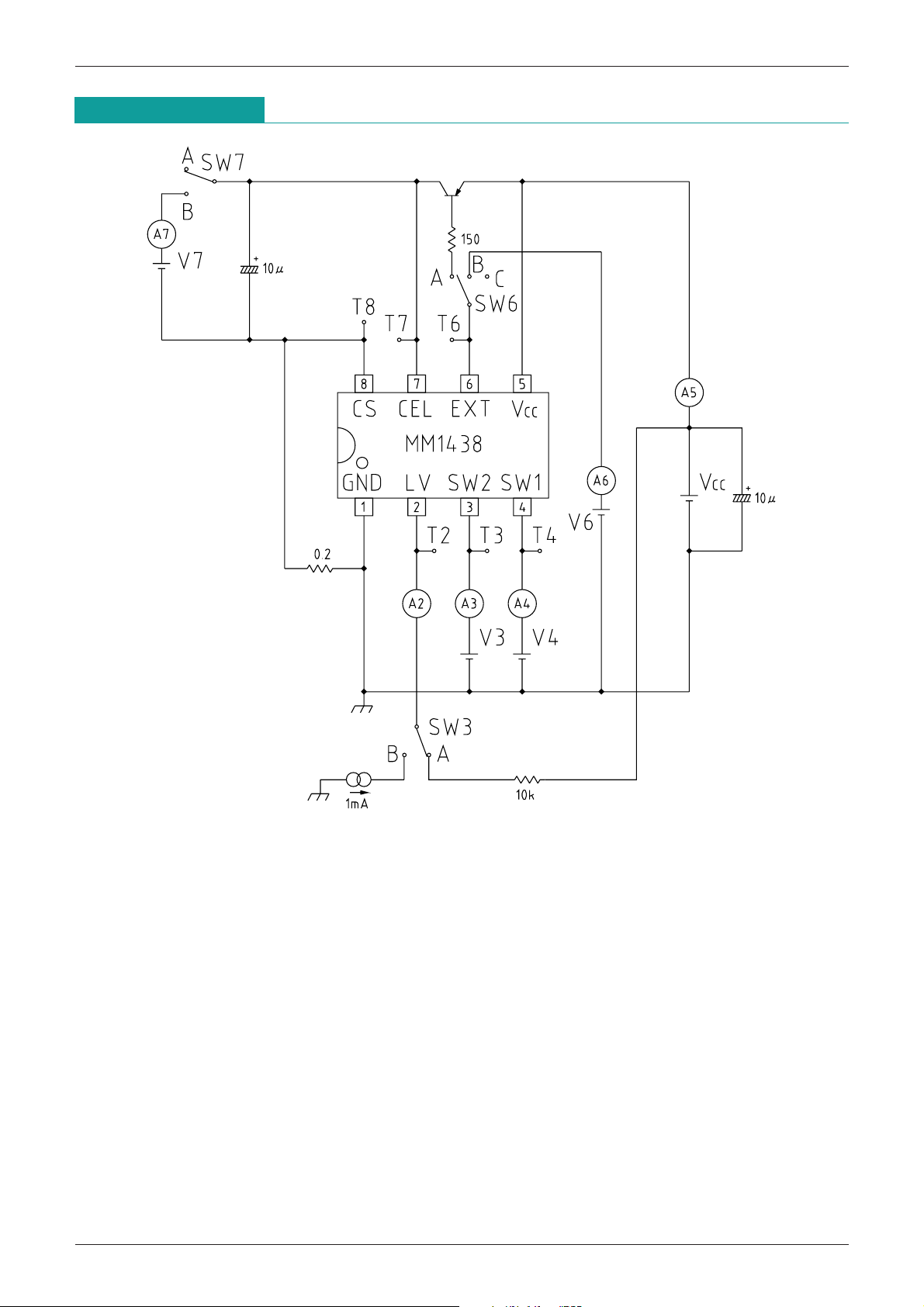
(Except where noted otherwise, Ta=25°C, VCC=5V, SW3 : A, SW6 : A, SW7 : A)
Item Symbol Measurement conditions Min. Typ. Max. Unit
Consumption current 1 I
Consumption current 2 I
Output voltage 1 V
Output voltage 2 V
Current limit V
CC1 VSW1=VSW2=0V (Charge : ON) 250 400 µA
CC2 VSW1=VSW2=VCC (Charge : OFF) 2 10 µA
O1 Ta=25°C 4.100 4.125 4.150 V
O2 Ta=0~50°C 4.095 4.125 4.155 V
CL 90 100 110 mV
Inflow current between
CEL1 3.0 5.0 7.0 µA
CEL-CS during operation
Leak current between CEL-CS
SW1 input current I
SW1 input voltage L V
SW1 input voltage H V
Low voltage detection voltage
SW2 input current I
SW2 input current L V
SW2 input current H V
I
ICEL2 VCC=0V or OPEN 0.01 1 µA
SW1 20 30 µA
L1 Charge : ON
H1 Charge : OFF
-
0.3 2.0 V
VCC-
0.1 VCC+0.3
LV 2.0 2.15 2.3 V
SW2 20 30 µA
L2 Low voltage detection circuit: ON
H2 Low voltage detection circuit: OFF
-
0.3 2.0 V
VCC-
1.0 VCC+0.3
Low voltage detection
LV 0.5 µA
output leak current
I
Low voltage detection
LV ISINK=1mA 0.2 0.4 V
output saturation voltage
V
EXT pin inflow current IEXT 10 20 mA
EXT pin output voltage V
EXT For no load 0.3
VCC-
Note 1: Please insert a capacitor of several µF between power supply and ground when using.
Note 2: Be sure that CS pin potential does not fall below
-
0.5V.
Note 3: If the IC is damaged and control is no longer possible, its safety can not be guaranteed. Please
protect with something other than this IC.
0.3
V
V
V
Page 4
MITSUMI
Measuring Circuit
IC for Control of Lithium-ion Betteries Charging MM1438
Page 5
MITSUMI
MITSUMI
IC for Control of Lithium-ion Betteries Charging MM1438
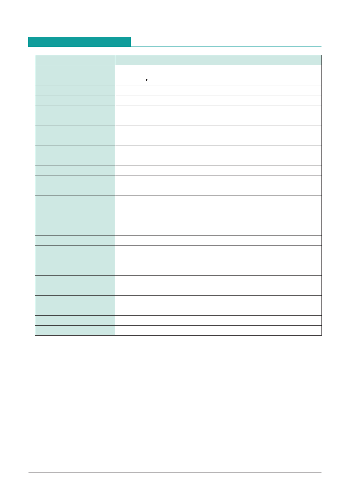
Measurement Procedures
Item Measurement Procedures
Consumption current 1
Consumption current 2 V3 = Vd = V
Output voltage V3 = V
Current limit
Inflow current between V3 = V
CEL-CS during operation I
Leak current between CEL-CS
SW1 input current Measure A4 current value I
SW1 input voltage
ow voltage detection voltage
L
V3 = V
from V
V3 = Vcc, V4 = 0V. Set V7 voltage 1V lower than T7 (output voltage) potential
and set SW7 to B. Measure T8 voltage V
CEL1 at this time.
V3 = V4 = VCC = 0V, SW6: C. V7 = 4.5V, SW7: B. Measure A7 current value
I
CEL2 at this time.
V3 = V
prescribed output voltage; Charge OFF (V
V3 = V4 = 0V. Set V7 voltage 1V lower than T7 (output voltage) potential, and
SW7: B.
Next gradually lower V7 voltage; V7 voltage is LV when A7 current value is
(Except where noted otherwise, Ta=25°C, VCC=5V, SW3 : A, SW6 : A, SW7 : A)
CC, V4 = 0V. Next, measure A5 current value Icc1 when V3 is changed
CC 0V.
CC. Measure A6 current value ICC2 at this time.
CC, V4 = 0V. Measure T7 voltage VO at this time.
CL at this time.
CC, V4 = 0V, SW6: C. V7 = 4.5V, SW7: B. Measure A7 current value
SW1 when V4 = 0V.
CC. Charge: ON (VL1) when V4 potential is varied and T7 voltage is the
H1) when 0 ~ 0.05V.
within ±10µA.
SW2 input current Measure A3 current value I
V4 = 0V, V7 = 1V, SW7: B. Low voltage detection circuit: ON (V
SW2 input voltage
Low voltage detection V3 = V
voltage is varied and A7 current value is within ±10µA; low voltage detection
circuit: OFF (V
CC, V4 = 0V. Measure A2 current value ILV when V3 is changed from
H2) otherwise.
output leak current Vcc 0V.
Low voltage detection
V3 = V4 = 0V. SW3: B, SW7: B. Measure T2 voltage VLVwhen V7 voltage is 0V.
output saturation voltage
EXT pin inflow current
EXT pin output voltage
V3 = V4 = 0V. SW6: B, SW7: B, V6 = 4V, V7 = 3V. Measure A6 current value I
V3 = V4 = 0V. SW6: C, SW7: B. T6 voltage when V7 = 3V and V7 = 5V is V
SW2 when V3 = 0V.
L2) when V3
EXT
EXT
.
.
Page 6
MITSUMI
Battery connection and SW1: ON
V
CC
OFF
OFF
ON
ON
SW1
CEL
CS
LV
CEL
CS
LV
Rated voltage mode
Charging ON
Rated current mode
Charging OFF
Charging OFF
Normal charging
Battery low voltage
(2V or less)
0
0
0
0
0
0
0
0
L
L
H
100mV
(SW2 : L)
MITSUMI
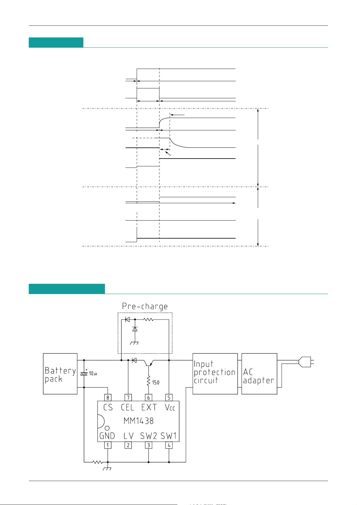
Timing Chart
IC for Control of Lithium-ion Betteries Charging MM1438
Application Circuit
Page 7
MITSUMI
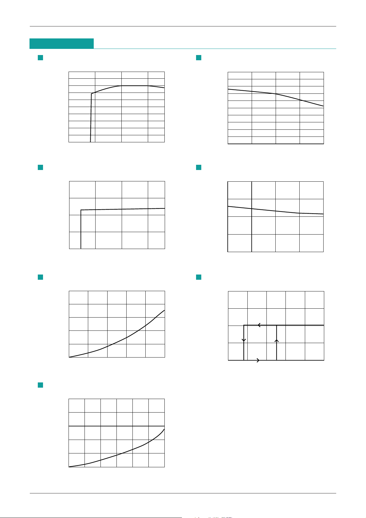
4.15
4.10
4.05
0 5 10 1815
(Ta=25°C)
Power supply voltage (V)
Output voltage (V)
4.15
4.10
4.05
-
25 0 25 7550
(VCC=5V)
Ambient temperature (°C)
Output voltage (V)
110
105
100
95
90
0 5 10 1815
(Ta=25°C)
Power supply voltage (V)
CS pin voltage (mV)
110
105
100
95
90
-
25 0 25 7550
(VCC=5V)
Ambient temperature (°C)
CS pin voltage (mV)
5
4
3
2
1
0
0 5 10 2515 20
(Ta=25°C)
LV pin inflow current (mA)
LV pin voltage (V)
200
150
100
50
0
2 2.1 2.2 2.52.3 2.4
(Ta=25°C,VCC=5V, at low voltage detection)
Output voltage (V)
CS pin voltage (mV)
5
4
3
2
1
0
0 5 10 3015 20 25
(Ta=25°C,VCC=5V)
EXT pin inflow current (mA)
EXT pin voltage (V)
Characteristics
IC for Control of Lithium-ion Betteries Charging MM1438
Output voltage vs Power supply voltage
CS pin voltage vs Power supply voltage
Output voltage vs Ambient temperature
CS pin voltage vs Ambient temperature
LV pin voltage vs LV pin inflow current
EXT pin voltage vs EXT pin inflow current
CS pin voltage vs Output voltage
 Loading...