

Page 1

MITSUMI
Protection of Lithium-Ion Batteries MM1421
Protection of Lithium-Ion Batteries
Monolithic IC MM1421
Outline
This IC is used to protect single-cell lithium-ion batteries. It adopts an ultra-compact package and has the
functions of previous models, with functions for overcharge detection, overdischarge detection and
overcurrent detection. A dead time can be set externally.
Features
1. Overcharge detection voltage accuracy (0°C to 50°C) ±25mV/cell
2. Consumption current (Vcell=3.6V) 10.0µA typ.
3. Consumption current (Vcell=1.9V) 0.1µA typ.
4. Overcharge sensing dead time can be set externally
5. Overdischarge reset reset by charging
Package
SOT-26A
Applications
IC for protection of single-cell lithium-ion batteries.
MITSUMI
Pin Assignment
123
654
SOT-26A
1 VM
2 V
CC
3 TD
4 CO
5 GND
6 DO
Page 2
MITSUMI
Protection of Lithium-Ion Batteries MM1421
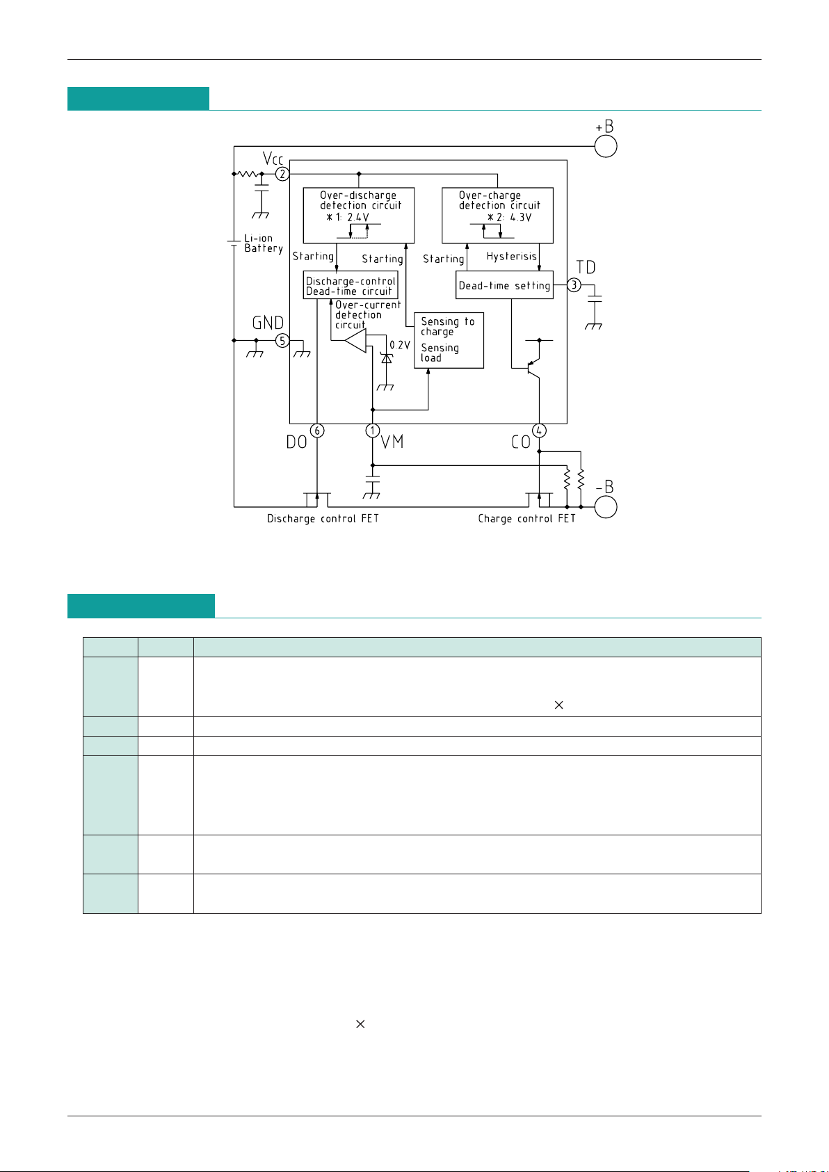
Block Diagram
Note 1 : Overdischarge voltage
Note 2 : Overcharge voltage
Pin Description
Pin No.
Pin Name
Function
1 V
M
Overcurrent detection input pin. Detects discharge current by connection to charging control
FET source pin.
Discharge current = (voltage between V
M
and GND) / (FET 2 ON resistance)
2 VCC Positive power supply pin.
3 TD Overcharge detection dead time setting pin.
4 CO
Charging control FET (N-ch) gate connection pin. An external resistor (910kΩ) is required
between gate and source. Turns off charging control FET (N-ch) for overcharge mode
(during charging) and overdischarge mode. Also, overcharge mode (during discharge)
turns charging control FET (N-ch) ON, and suppresses FET power consumption.
5 GND
Negative power supply pin. Also, negative input pin for battery connected between V
CC and
GND.
6 DO
Discharge control FET (N-ch) gate connection pin. Turns gate OFF for overdischarge
mode and overcurrent mode. Turns gate ON for overcharge mode and normal mode.
(1) Overcharge mode: Battery voltage > overcharge detection voltage
(2) Normal mode: Overdischarge detection voltage < battery voltage <overcharge detection voltage
Discharge current < overcurrent detection level
(3) Overdischarge mode: Overdischarge detection voltage > battery voltage
(4) Overcurrent mode: Discharge current > overcurrent detection level, voltage between V
M and GND =
discharge current FET ON resistance
(discharge/charge control FET)
Page 3
MITSUMI
Protection of Lithium-Ion Batteries MM1421
MITSUMI
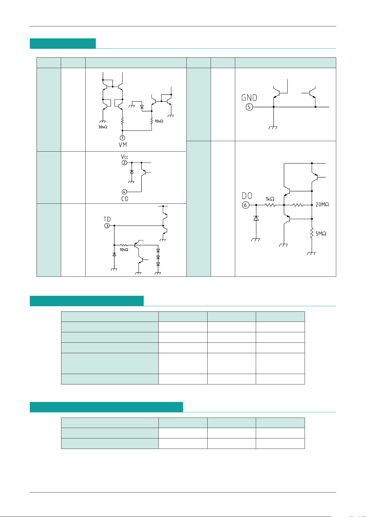
Pin Assignment
Pin No.
Pin name
Equivalent circuit diagram Pin No.
Pin name
Equivalent circuit diagram
1 V
M 5 GND
6 DO
2 V
CC
4 CO
3 TD
Absolute Maximum Ratings
(Ta=25°C)
Item Symbol Ratings Unit
Storage temparature T
STG
-
40~+125 °C
Operating temparature T
OPR
-
20~+70 °C
Supply voltage V
CC max.
-
0.3~+18 V
CO pin voltage V
CO max.
V
CC
-
28~VCC V
V
M pin voltage VVM max.
Allowable loss Pd 200 mW
Recommended Operating Conditions
Item Symbol Ratings Unit
Operating temparature T
OPR
-
20~+70 °C
Power supply voltage V
OP +1.8~+10 V
Page 4

MITSUMI
Protection of Lithium-Ion Batteries MM1421
MITSUMI
Electrical Characteristics
(Except where noted otherwise, Ta=25°C, VCC=3.6V)
Item Symbol Measurement conditions Min. Typ. Max. Unit
Consumption current 1
I
CC1
VCC = 3.6V: Set state
10.0 14.0 uA
(condition: SET) between CO-GND: 910kΩ connected
Consumption current 2
I
CC2
VCC = 3.6V: IC alone
6.0 10.0 uA
(condition: IC only) between CO-GND: 910kΩ not connected
Consumption current 3
I
CC3
VCC=3.6V: Discharge FET OFF state
uA
(FET: OFF on SET) between CO-GND: 910kΩ not connected
Consumption current 4
I
CC4
VCC=1.9V: Discharge FET OFF state
0.2 1.0 uA
(FET: OFF on SET) between CO-GND: 910kΩ not connected
Consumption current 5
I
CC5
V
CC
=4.5V between CO-GND: 910kΩ connected
35 60 uA
(condition: SET)
Overcharge detection voltage
VALM1 Ta=0~50°C VCC: L H 4.325 4.350 4.375 V
Overcharge hysterisis voltage
VALM1 VCC: H L 100 200 300 mV
Overdischarge detection voltage
VALM2 VCC: H L 2.30 2.40 2.50 V
Release overdischarge voltage
2.88 3.00 3.12 V
Overcurrent detection level V
VMD VVM: L H 174 200 226 mV
Release overcurrent level V
VMDF VVM: H L 130 mV
Condition of release
Load condition 50 MΩ
overcurrent
Short detection voltage V
VMSHT 1.3 V
Overdischarge detection dead time
tALM2 7.0 10.0 15.0 mS
Overcurrent detection dead time
tVMD VM: 0V 0.5V 7.0 10.0 15.0 mS
Short detection delay time
tVMSHT VM: 0V 2V 0.02 0.20 mS
Overcharge detection dead time
tALM1 CTD=0.01µF 50 100 150 mS
DO pin output voltage V
GDH VCC=3.6V
VCC-
0.3 VCC-
0.1
VCC V
DO pin source current 1 I
DOH1 VDO=VCC
-
1.0V
-
100-30 uA
DO pin source current 2 I
DOH2 VDO=VCC
-
0.3V
-
0.40-0.70 uA
DO pin sink current 1 I
DOL1 VVM>1.0V, VDO=1.0V 50 300 uA
DO pin sink current 2 I
DOL2 VVM>1.0V, VDO=0.3V 30 100 uA
DO pin sink current 3 I
DOL3 VCC=3.6V, VDO=1V (Stand-by mode) 1 5 uA
CO pin source current 1 I
CO1 VCO=VCC
-
1.0V
-
20-10 uA
CO pin source current 2 I
CO2 VCO=VCC
-
0.3V
-
15
-
5uA
CO pin source current 3 I
CO3 VCO=VCC
-
0.3V (Stand-by mode) uA
Starting trigger voltage V
ST VVM: 0V
-
0.5V
-
0.2-0.1 0 V
Note: Overcurrent detection current value is VVM/(FET ON resistance 2).
Page 5

MITSUMI
Protection of Lithium-Ion Batteries MM1421
MITSUMI
Note :
Measuring Circuit
Measuring circuit 1
Measuring circuit 2
0.5V or 2V
GND
GND
t VM
VM
DO
3.0V
2.2V
-
1V/100µS
VDO
GND
GND
t DO
VCC
DO
1V/100µS
V
ALM
t ALM
4.0V
4.5V
GND
GND
VCC
CO
Page 6

MITSUMI
Protection of Lithium-Ion Batteries MM1421
Application Circuit
Timing Chart
Over-charge voltage
Dead time
Dead time
GND level
Charge mode Discharge mode
Charge mode
Discharge mode
Overdischarge voltage
Dead time
Excess discharge
current mode
Excess
discharge mode
CELL pin
voltage
TD pin voltage
CO pin voltage
DO pin voltage
VM
pin
voltage
Hystarasia
Page 7

MITSUMI
Protection of Lithium-Ion Batteries MM1421
Characteristics
External capacitor (µF)
10
1
0.1
0.01
0.01 0.1 1
Dead time of overcharge
detection : t TD (S)
Power supply voltage : VCC (V)
(When V
CC : H L)
1.2
1.0
0.8
0.6
0.4
0.2
0
01234536
Power supply current : ICC (µA)
Power supply voltage : VCC (V)
(When V
CC : H L)
60
50
40
30
20
10
0
01234536
Power supply current : ICC (µA)
DO pin voltage (V)
600
400
200
0.6
0.4
0.2
1.0 2.0 3.0
(Right ax is)
DO source current (µA)
DO source current (µA)
Dead time vs external capacitor
When overcharge detection
Power supply current vs power supply voltage
When stand-by mode
Power supply current vs power supply voltage
DO source current - DO pin voltage
V
CC=3.6V
 Loading...