

Page 1
MITSUMI
1432
8567
VSOP-8A
MITSUMI
Protection of Lithium-Ion Batteries MM1412
Protection of Lithium-Ion Batteries
Monolithic IC MM1412
Outline
This IC is used to protect lithium-ion batteries consisting of two cells. It adopts a compact package and has
the functions of previous models, with functions for overcharge detection, overdischarge detection and
overcurrent detection. A dead time can be set externally.
Features
1. Overcharge detection voltage accuracy (0°C to 50°C) ±25mV/cell
2. Consumption current (Vcell=4.5V) 150µA typ.
3. Consumption current (Vcell=3.5V) 15.0µA typ.
4. Consumption current (Vcell=1.9V) 0.5µA typ.
5. Overcharge sensing dead time can be set externally.
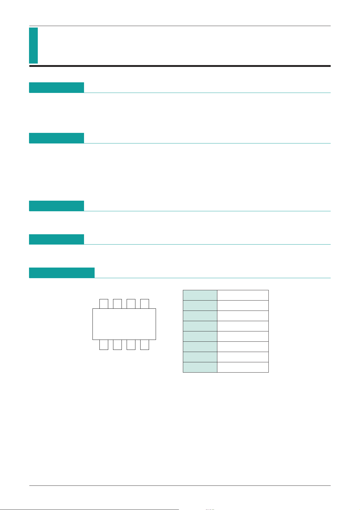
Package
VSOP-8A
Applications
IC for protection of lithium-ion batteries consisting of two cells.
Pin Assignment
1 OC
2 GD
3 CS
4 GND
5 TD
6 VL
7 V
8 VH
CC
Page 2
MITSUMI
MITSUMI
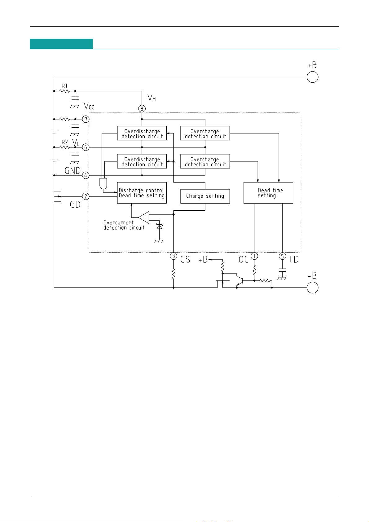
Block Diagram
Protection of Lithium-Ion Batteries MM1412
Page 3

MITSUMI
Pin Description
Protection of Lithium-Ion Batteries MM1412
Pin No.
Pin name
Functions
Overcharge detection output pin
PNPT
R open collector output
1 OC
Overcharge mode: ON
Normal mode, overdischarge mode, overcurrent mode: OFF
Discharge control FET (N-ch) control output pin
2 GD Normal mod, overcharge mode: H
Overdischarge mode, overcurrent mode: L
Overcurrent detection input pin
Monitors discharge current equivalently by the voltage drop between discharge control FET source
3 CS
and drain. Stops discharge when voltage between CS pin and GND pin goes above overcurrent
detection threshold value, and holds until load is released.
4 GND Ground pin, or lower cell load negative pole input pin.
Overcharge detection dead time setting pin
5 TD
Dead time can be set by adding a capacitor between TD and GND pins.
Battery intermediate potential input pin
6 VL
Connection pin for lower cell positive electrode side and upper cell negative electrode side.
7 V
CC Power supply input pin
8 VH Upper cell positive electrode input pin
Note: Mode Descriptions
(1) Overcharge mode
Either H cell or L cell battery voltage exceeds overcharge detection voltage. Overcharge detection
operation delay can be set by the dead time setting pin.
(2) Normal mode
Both H and L cell battery voltages exceed overdischarge detection voltage and are less than
overcharge detection voltage.
(3) Overdischarge mode
Either H or L cell battery voltage is less than overdischarge detection voltage.
Overdischarge detection dead time is set internally. Overdischarge mode is released when charging
causes voltage to rise above overdischarge detection voltage. Also, when battery voltage goes above
overdischarge release voltage, it resets without charging, but the value is set high. (This function is
included in case charging can not be detected. Also, this release voltage has a temperature coefficient
of
-
6mV/°C.)
(4) Overcurrent mode
Voltage between CS and GND exceeds overcurrent detection voltage during discharge.
Page 4

MITSUMI
Protection of Lithium-Ion Batteries MM1412
Absolute Maximum Ratings
(Ta=25°C)
Item Symbol Ratings Unit
Storage temperature T
Operating temperature T
Power supply voltage V
OC pin impressed voltage V
CS pin impressed voltage V
Allowable loss Pd 300 mW
Recommended Operating Conditions
Item Symbol Ratings Unit
Operating temperature T
Operating power supply voltage V
Electrical Characteristics
(Except where noted otherwise, Ta=25°C)
STG
OPR
CC max.
OC max.
CS max.
OPR
OP +0.9~+18 V
-
40~+125 °C
-
20~+70 °C
-
0.3~+18 V
-
0.6~VCC V
-
0.6~VCC V
-
20~+70 °C
Item Symbol Measurement conditions Min. Typ. Max. Unit
Overcharge detection voltage
Overcharge detection hysteresis voltage
Overdischarge detection voltage
Consumption current 1 I
Consumption current 2 I
Consumption current 3 I
Consumption current 4 I
VL pin input current I
Overdischarge release voltage
GD pin H output voltage V
GD pin L output voltage V
OC pin output current I
Overcurrent detection threshold value
Overcurrent short threshold value
Overcurrent release
Overcurrent detection delay time 1
Overcurrent detection delay time 2
Overdischarge detection delay time
Overcharge detection dead time
Start-up voltage V
VOC Ta=0°C~50°C 4.325 4.350 4.375 V
VOC 170 220 270 mV
VOD 2.20 2.30 2.40 V
VH1 VH=VL=1.0V VCS=1.4V 0.1 µA
VH2 VH=VL=1.9V VCS=3.2V 0.5 0.8 µA
VH3 VH=VL=3.5V 15.0 20.0 µA
VH4 VH=VL=4.5V, ROC=270kΩ 150 µA
VL VH=VL=3.5V
-
0.3 0 0.3 µA
VDF Discharge resume by voltage rise 3.30 3.50 3.70 V
GDH VH=VL=3.5V, IL=
GDL VH=VL=3.5V, IL=10µA 0.2 0.3 V
OCH VH=VL=4.5V 30 150 µA
-
10µA
VH-
0.3 VH-
VCS1 135 150 165 mV
VCS2 When both battery pack pins are shorted 0.35 0.45 0.55 V
Load release: Load of 5MEGΩ or more between both battery pack pins
tOC1 7 12 18 mS
tOC2
1 30 100 uS
*
tOD 81320mS
tOCH CTC=0.18µF 0.5 1.0 1.5 S
ST VH=VL=2.5V
-
0.24-0.12-0.04 V
Note 1: Overcurrent short mode delay time (overcurrent delay time 2) is IC response speed.
In actual use, the time for discharging the discharge control FET gate capacity is added.
Also, when voltage change is large due to excess current, the IC internal bias current may turn off
temporarily, causing response time to lengthen. Select the time constant for the capacitor
connected to the power supply pin so that power supply fluctuation is more than 100µS/1V.
0.2
V
Note 2: Calculate overcharge dead time according to the following formula:
Overcharge detection dead time: t
ALM
-
5.55 CTD[S]
[CTD: external capacitor, Unit:µF]
Page 5

MITSUMI
0.2V
CS
GD
0V
t OC
t OC
2.5V
2.0V
VL
GD
1V/100µS
VOD
t OCH
4.5V
4.0V
OC
V
L
1V/100µ S
VOC
MITSUMI
Measuring Circuit
Measuring Circuit 1
(V
OC, VOC, VOD, VDF, VST, VCS, IDCH, VGDH, VGDL)
Measuring Circuit 2
OC, tOD, tOCH)
(t
Protection of Lithium-Ion Batteries MM1412
Note :
Page 6

MITSUMI
VH
VH
Dischage
control
dead time
setting
GD
TD
OC
Overcharge
Overdischarge
Overcharge
Overdischarge
Gate off
Keep cirquit
Over current
dead time
Open load
Overcharge
Over load
Charge sensing
dead time Overdischarge
dead time
HI-impedance
Power down
Power
down
Short load
Overdischarge
detection
Overdischarge
Keep overcharge
Overdischarge
dead time
MITSUMI
Timing Chart
Protection of Lithium-Ion Batteries MM1412
Application Circuit
Page 7

MITSUMI
0.001 0.01 0.1
0.001
0.01
0.1
1
External capacitance (CTD)
Overcharge detection time (S)
Characteristics
Overcharge Detection Time (Dead Time)
Note: Dead time can be calculated according to the following formula:
tOC=5.55 CTD [S]
tOC=Overcharge Detection Time
CTD=External Capacitor···Unit : µF
Protection of Lithium-Ion Batteries MM1412
 Loading...