

Page 1
MIC915 Micrel
MIC915
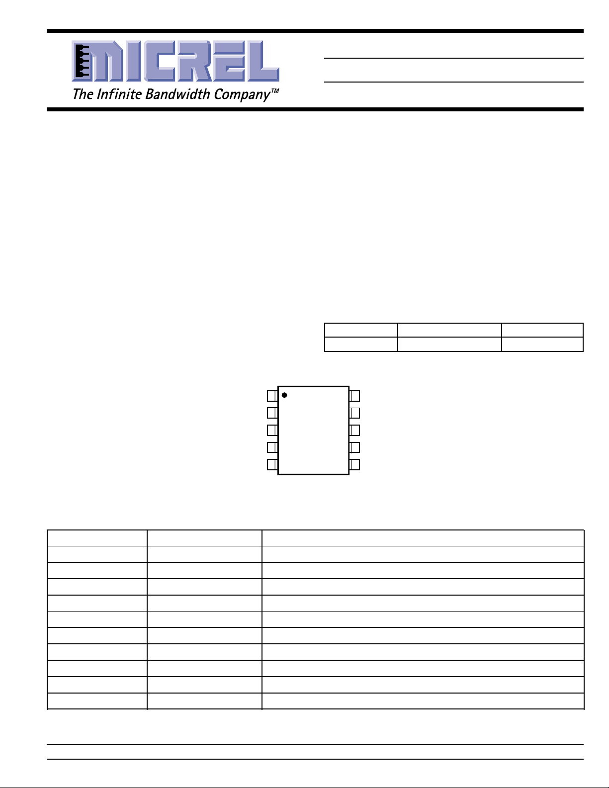
Dual 135MHz Low-Power Op Amp
General Description
The MIC915 is a high-speed, unity-gain stable operational
amplifier. It provides a gain-bandwidth product of 135MHz
with a very low, 2.4mA supply current per op amp.
Supply voltage range is from ±2.5V to ±9V, allowing the
MIC915 to be used in low-voltage circuits or applications
requiring large dynamic range.
The MIC915 is stable driving any capacitative load and
achieves excellent PSRR, making it much easier to use than
most conventional high-speed devices. Low supply voltage ,
low power consumption, and small packing make the MIC915
ideal for portable equipment. The ability to drive capacitative
loads also makes it possible to drive long coaxial cables.
Pin Configuration
1
INA–
2
INA+
3
V+(A)
4
INB–
5
INB+
Features
• 135MHz gain bandwidth product
• 2.4mA supply current per op amp
• MSOP-10 package
• 270V/µs slew rate
• drives any capacitive load
Applications
• Video
• Imaging
• Ultrasound
• Portable equipment
• Line drivers
Ordering Information
Part Number Junction Temp. Range Package
MIC915BMM –40°C to +85°C MSOP-10
10
V–(A)*
9
OUTA
8
V–(B)*
7
OUTB
6
V+(B)
MSOP-10
Pin Description
Pin Number Pin Name Pin Function
1 INA– Inverting Input A
2 INA+ Noninverting Input A
3 V+(A) Positive Supply Input (Op Amp A)
4 INB– Inverting Input B
5 INB+ Noninverting Input B
6 V+(B) Positive Supply Input (Op Amp B)
7 OUTB Output B
8V–(B) Negative Supply Input* (Op Amp B)
9 OUTA Output A
10 V–(A) Negative Supply Input* (Op Amp A)
* V– pins must be externally shorted together
Micrel, Inc. • 1849 Fortune Drive • San Jose, CA 95131 • USA • tel + 1 (408) 944-0800 • fax + 1 (408) 944-0970 • http://www.micrel.com
September 2000 1 Rev 8/00-A MIC915
Page 2

MIC915 Micrel
Absolute Maximum Ratings (Note 1)
Supply Voltage (V
Differentail Input Voltage (V
Input Common-Mode Range (V
– VV–)...........................................20V
V+
IN+
– V
IN+
) ..........8V, Note 4
IN–
, V
) .......... VV+ to V
IN–
Operating Ratings (Note 2)
Supply Voltage (V
Junction Temperature (T
Package Thermal Resistance ...............................260°C/W
V–
) ....................................... ±2.5V to ±9V
S
) ......................... –40°C to +85°C
J
Lead Temperature (soldering, 5 sec.) .......................260°C
Storage Temperature (T
) ........................................ 150°C
S
ESD Rating, Note 3 ................................................... 1.5kV
Electrical Characteristics (±5V)
VV+ = +5V, VV– = –5V, VCM = 0V, V
Symbol Parameter Condition Min Typ Max Units
V
OS
V
OS
Input Offset Voltage 1 15 mV
Input Offset Voltage 4 µV/°C
Temperature Coefficient
I
B
I
OS
V
CM
Input Bias Current 3.5 5.5 µA
Input Offset Current 0.05 3 µA
Input Common-Mode Range CMRR > 60dB –3.25 +3.25 V
CMRR Common-Mode Rejection Ratio –2.5V < V
PSRR Power Supply Rejection Ratio ±5V < V
A
V
VOL
OUT
Large-Signal Voltage Gain RL = 2k, V
Maximum Output Voltage Swing positive, RL = 2kΩ +3.3 3.5 V
GBW Gain-Bandwidth Product RL = 1kΩ 125 MHz
BW –3dB Bandwidth AV = 1, RL = 100Ω 192 MHz
SR Slew Rate 230 V/µs
Crosstalk f=1MHz 82 dB
I
GND
I
Q
Short-Circuit Output Current source 72 mA
Supply Current per Op Amp 2.4 3.5 mA
= 0V; RL = 10MΩ; TJ = 25°C, bold values indicate –40°C ≤ TJ ≤ +85°C; unless noted.
OUT
< +2.5V 70 90 dB
CM
60 dB
< ±9V 74 81 dB
S
70 dB
= ±2V 60 71 dB
OUT
RL = 200Ω, V
= ±2V 60 71 dB
OUT
+3.0 V
negative, R
positive, R
= 2kΩ –3.5 –3.3 V
L
= 200Ω +3.0 3.2 V
L
+2.75 V
negative, R
= 200Ω –2.8 –2.45 V
L
sink 25 mA
9 µA
–3.0 V
–2.2 V
4.1 mA
Electrical Characteristics
VV+ = +9V, VV– = –9V, VCM = 0V, V
Symbol Parameter Condition Min Typ Max Units
V
OS
V
OS
Input Offset Voltage 1 15 mV
Input Offset Voltage 4 µV/°C
Temperature Coefficient
I
B
Input Bias Current 3.5 5.5 µA
MIC915 2 September 2000
= 0V; RL = 10MΩ; TJ = 25°C, bold values indicate –40°C ≤ TJ ≤ +85°C; unless noted
OUT
9 µA
Page 3

MIC915 Micrel
Symbol Parameter Condition Min Typ Max Units
I
OS
V
CM
CMRR Common-Mode Rejection Ratio –6.5V < V
A
VOL
V
OUT
GBW Gain-Bandwidth Product RL = 1kΩ 135 MHz
SR Slew Rate 270 V/µs
I
GND
I
GND
Note 1. Exceeding the absolute maximum rating may damage the device.
Note 2. The device is not guaranteed to function outside its operating rating.
Note 3. Devices are ESD sensitive. Handling precautions recommended. Human body model, 1.5k in series with 100pF.
Note 4. Exceeding the maximum differential input voltage will damage the input stage and degrade performance (in particular, input bias current is
Input Offset Current 0.05 3 µA
Input Common-Mode Range CMRR > 60dB –7.25 +7.25 V
< 6.5V 70 98 dB
CM
60 dB
Large-Signal Voltage Gain RL = 2kΩ, V
= ±6V 60 73 dB
OUT
Maximum Output Voltage Swing positive, RL = 2kΩ +7.2 +7.4 V
+6.8 V
negative, R
= 2kΩ –7.4 –7.2 V
L
Crosstalk f = MHz 82 dB
Short-Circuit Output Current source 90 mA
sink 32 mA
Supply Current per Op Amp 2.5 3.7 mA
likely to increase.
–6.8 V
4.3 mA
Test Circuits
BNC
Input
10k
BNC
Input
V
CC
10µF
0.1µF
50Ω
0.1µF
50Ω
2k
0.1µF
10µF
V
EE
10k
10k
50Ω
All resistors:
1% metal film
0.1µF
PSRR vs. Frequency
BNC
Output
Input
BNC
R1 5k
R7c 2k
R7b 200Ω
R7a 100Ω
All resistors 1%
VV
=++
OUT ERROR
R6
5k
R2R1R2 R R4
1
CMRR vs. Frequency
R3
200k
250Ω
R5
5k
R4
++
5
R7
R2
5k
V
CC
10µF
0.1µF
0.1µF
10µF
V
EE
BNC
Output
September 2000 3 Rev 8/00-A MIC915
Page 4

MIC915 Micrel
c
r
100pF
V
CC
R1
20Ω
R5
20Ω
10pF
R3 27k
S1
S2
R4 27k
10pF
R2 4k
10µF
0.1µF
0.1µF
10µF
V
EE
Noise Measurement
BNC
To
Dynami
Analyze
MIC915 4 September 2000
Page 5

MIC915 Micrel
1.0
1.5
2.0
2.5
-40 -20 0 20 40 60 80 100
OFFSET VOLTAGE (mV)
TEMPERATURE (°C)
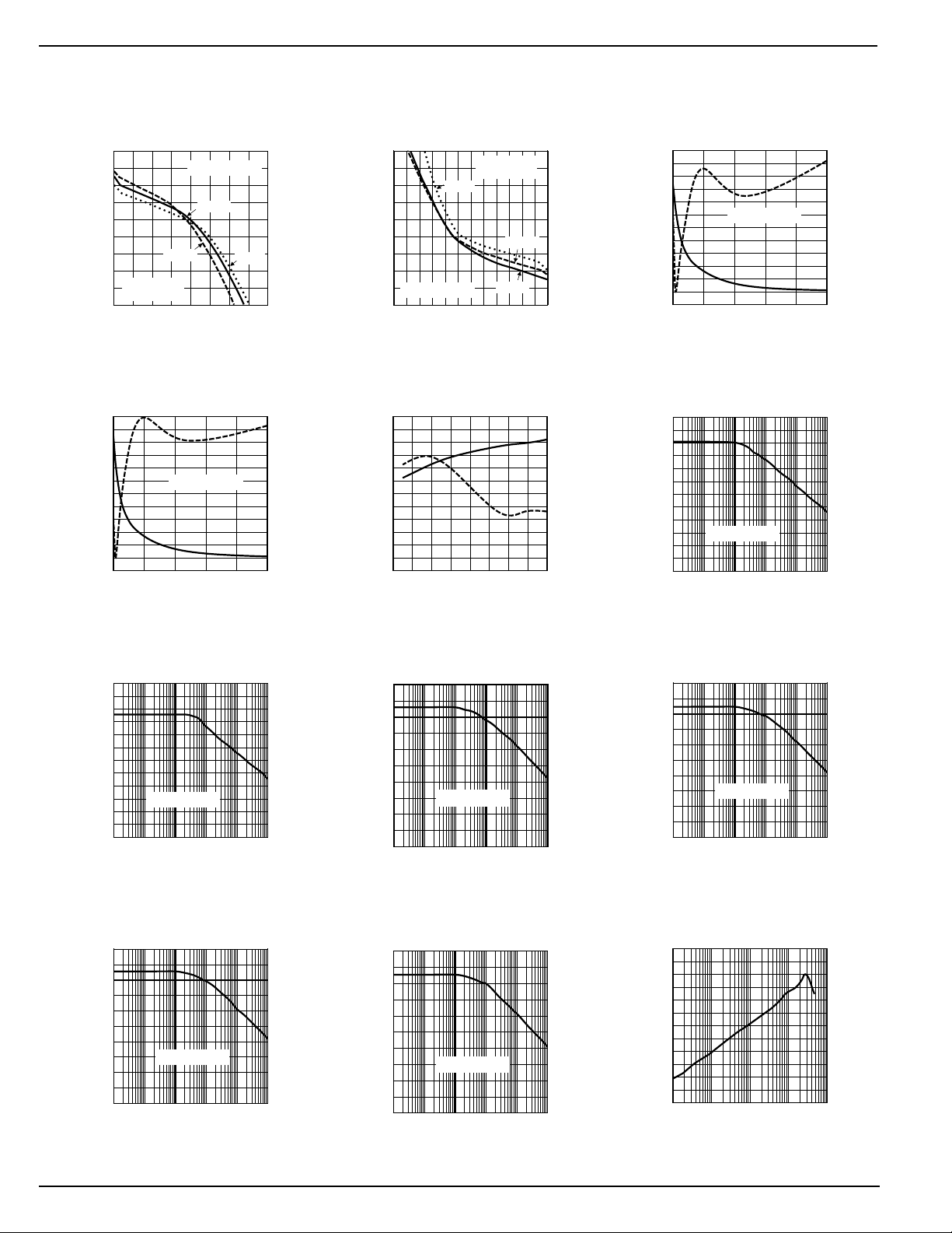
Offset Voltage
vs. Temperature
V
SUPPLY
= ±5V
V
SUPPLY
= ±9V
0
1
2
3
4
5
6
-8-6-4-202468
OFFSET VOLTGE (mV)
COMMON-MODE VOLTAGE (V)
0
1
2
3
4
5
6
7
8
9
10
0 20406080100
OUTPUT VOLTAGE (V)
OUTPUT CURRENT (mA)
Electrical Characteristics
Supply Current
vs. Supply Voltage
3.5
+85°C
3.0
2.5
SUPPLY CURRENT (mA)
2.0
2345678910
SUPPLY VOLTAGE (±V)
+25°C
-40°C
Bias Current
vs. Temperature
5
4
V
= ±5V
V
SUPPLY
SUPPLY
= ±9V
3
2
BIAS CURRENT (µA)
1
-40 -20 0 20 40 60 80 100
TEMPERATURE (°C)
Supply Current
vs. Temperature
4.0
3.5
V
= ±9V
SUPPLY
3.0
2.5
SUPPLY CURRENT (mA)
2.0
-40 -20 0 20 40 60 80 100
TEMPERATURE (°C)
V
SUPPLY
= ±5V
Offset Voltage
vs. Common-Mode Voltage
V
= ±9V
SUPPLY
+85°C
-40°C
+25°C
Offset Voltage
vs. Common-Mode Voltage
5
4
3
2
-40°C
1
OFFSET VOLTGE (mV)
0
-5 -4 -3 -2 -1 0 1 2 3 4 5
COMMON-MODE VOLTAGE (V)
+85°C
+25°C
V
SUPPLY
= ±5V
SUPPLY CURRENT (mA)
-15
-20
-25
September 2000 5 Rev 8/00-A MIC915
-30
-35
OUTPUT CURRENT (mA)
-40
Short-Circuit Current
vs. Temperature
95
90
85
80
75
70
65
60
55
-40 -20 0 20 40 60 80 100
V
SUPPLY
SOURCING
CURRENT
V
= ±5V
SUPPLY
TEMPERATURE (°C)
= ±9V
Short-Circuit Current
vs. Supply Voltage
-40°C
+85°C
SINKING
CURRENT
2345678910
SUPPLY VOLTAGE (±V)
+25°C
Short-Circuit Current
vs. Temperature
-20
-25
-30
-35
SUPPLY CURRENT (mA)
-40
-40 -20 0 20 40 60 80 100
V
= ±5V
SUPPLY
SINKING
CURRENT
V
= ±9V
SUPPLY
TEMPERATURE (°C)
Output Voltage
vs. Output Current
V
= ±9V
SUPPLY
+25°C
-40°C
SOURCING
CURRENT
+85°C
Short-Circuit Current
vs. Supply Voltage
100
80
60
40
OUTPUT CURRENT (mA)
20
2345678910
-40°C
+25°C
+85°C
SOURCING
CURRENT
SUPPLY VOLTAGE (±V)
Output Voltage
vs. Output Current
0
-1
-2
-3
-4
+25°C
-5
-6
-7
-8
OUTPUT VOLTAGE (V)
V
-9
SUPPLY
-10
-40 -30 -20 -10 0
OUTPUT CURRENT (mA)
-40°C
+85°C
= ±9V
SINKING
CURRENT
Page 6
MIC915 Micrel
Output Voltage
vs. Output Current
4.5
4.0
3.5
3.0
2.5
2.0
1.5
1.0
OUTPUT VOLTAGE (V)
SOURCING
0.5
CURRENT
0
0 20406080
OUTPUT CURRENT (mA)
+85°C
V
SUPPLY
+25°C
= ±5V
-40°C
Gain Bandwidth and
Phase Margin vs. Load
150
125
100
75
50
25
GAIN BANDWIDTH (MHz)
0
0 200 400 600 800 1000
V
= ±9V
SUPPLY
CAPACITIVE LOAD (pF)
Output Voltage
vs. Output Current
0.0
-0.5
-1.0
-1.5
-2.0
-2.5
-3.0
-3.5
OUTPUT VOLTAGE (V)
-4.0
V
SUPPLY
-4.5
-30 -25 -20 -15 -10 -5 0
OUTPUT CURRENT (mA)
-40°C
= ±5V
SINKING
CURRENT
+25°C
+85°C
Gain Bandwidth and
Phase Margin vs. Supply Voltage
46
44
42
40
38
PHASE MARGIN (°)
36
34
150
125
100
75
50
25
GAIN BANDWIDTH (MHz)
0
2345678910
SUPPLY VOLTAGE (±V)
54
52
50
48
46
PHASE MARGIN (°)
44
42
Gain Bandwidth and
Phase Margin vs. Load
150
125
100
75
50
25
GAIN BANDWIDTH (MHz)
0
0 200 400 600 800 1000
V
= ±5V
SUPPLY
CAPACITIVE LOAD (pF)
Common-Mode
120
100
CMRR (dB)
Rejection Ratio
80
60
40
20
V
= ±9V
SUPPLY
0
1x1021x1031x1041x1051x1061x10
FREQUENCY (Hz)
46
44
42
40
38
PHASE MARGIN (°)
36
34
7
Common-Mode
120
100
CMRR (dB)
Rejection Ratio
80
60
40
20
V
= ±5V
SUPPLY
0
1x1021x1031x1041x1051x1061x10
FREQUENCY (Hz)
Positive Power Supply
100
+PSRR (dB)
Rejection Ratio
80
60
40
20
0
V
= ±5V
SUPPLY
1x1021x1031x1041x1051x1061x10
FREQUENCY (Hz)
Positive Power Supply
100
+PSRR (dB)
7
Rejection Ratio
80
60
40
20
0
V
= ±9V
SUPPLY
1x1021x1031x1041x1051x1061x10
FREQUENCY (Hz)
7
Negative Power Supply
100
–PSRR (dB)
7
Rejection Ratio
80
60
40
20
0
V
= ±5V
SUPPLY
1x1021x1031x1041x1051x1061x10
FREQUENCY (Hz)
7
Negative Power Supply
100
–PSRR (dB)
Rejection Ratio
80
60
40
20
0
V
= ±9V
SUPPLY
1x1021x1031x1041x1051x1061x10
FREQUENCY (Hz)
Cross Talk
0
-20
-40
-60
-80
CROSS TALK (dB)
-100
-120
1E+5
1E+6
1E+7
FREQUENCY (Hz)
1E+8
7
1E+9
MIC915 6 September 2000
Page 7
MIC915 Micrel
-50
-40
-30
-20
-10
0
10
20
30
40
50
1 10 100 200
GAIN (dB)
FREQUENCY (MHz)
-50
-40
-30
-20
-10
0
10
20
30
40
50
1 10 100 200
GAIN (dB)
FREQUENCY (MHz)
0
50
100
150
200
250
0 200 400 600 800 1000
SLEW RATE (V/µs)
LOAD CAPACITANCE (pF)
0
50
100
150
200
250
300
0 200 400 600 800 1000
SLEW RATE (V/µs)
LOAD CAPACITANCE (pF)
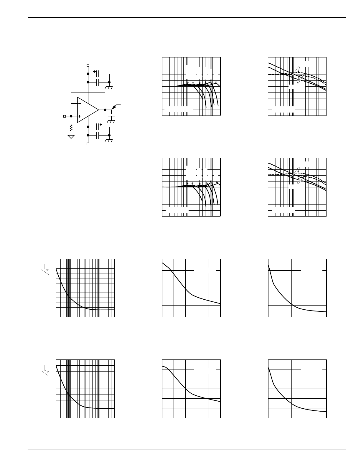
Closed-Loop
Frequency Response
Test Circuit
V
CC
10µF
0.1µF
MIC915
RF
50Ω
10µF
V
EE
FET probe
C
L
Closed-Loop
Frequency Response
1000pF
500pF
100pF
200pF
VCC = ±2.5V
Closed-Loop
Frequency Response
1000pF
500pF
100pF
200pF
VCC = ±5V
50pF
50pF
Open-Loop
Frequency Response
50
40
30
0p
20
10
0
-10
GAIN (dB)
-20
-30
VCC = ±5V
-40
-50
1 10 100200
RL=100Ω
No Load
FREQUENCY (MHz)
225
180
135
90
45
0
-45
-90
-135
-180
-225
PHASE (°)
Open-Loop
Frequency Response
50
40
30
0p
20
10
0
-10
GAIN (dB)
-20
-30
VCC = ±9V
-40
-50
1 10 100200
RL=100Ω
No Load
FREQUENCY (MHz)
225
180
135
90
45
0
-45
-90
-135
-180
-225
PHASE (°)
120
Hz
100
nV
80
60
40
20
NOISE VOL TAGE
0
1x1011x1021x1031x1041x10
5
Hz
4
pA
3
September 2000 7 Rev 8/00-A MIC915
2
1
NOISE CURRENT
0
1x1011x1021x1031x1041x10
Voltage
Noise
FREQUENCY (Hz)
Current
Noise
FREQUENCY (Hz)
Positive
Slew Rate
VCC = ±5V
5
250
200
150
100
SLEW RATE (V/µs)
50
0
0 200 400 600 800 1000
Positive
Slew Rate
VCC = ±9V
5
300
250
200
150
100
SLEW RATE (V/µs)
50
0
0 200 400 600 800 1000
Negative
Slew Rate
VCC = ±5V
LOAD CAPACITANCE (pF)
Negative
Slew Rate
VCC = ±9V
LOAD CAPACITANCE (pF)
Page 8

MIC915 Micrel
OUTPUT INPUT
Small-Signal
Pulse Response
VCC = ±9V
= 1
A
V
= 1.7pF
C
L
= 10MΩ
R
L
Small-Signal
Pulse Response
VCC = ±9V
= 1
A
V
= 100pF
C
L
= 10MΩ
R
L
OUTPUT INPUT
Small-Signal
Pulse Response
VCC = ±5V
= 1
A
V
= 1.7pF
C
L
= 10MΩ
R
L
Small-Signal
Pulse Response
VCC = ±5V
= 1
A
V
= 100pF
C
L
= 10MΩ
R
L
OUTPUT INPUT
OUTPUT INPUT
Small-Signal
Pulse Response
VCC = ±9V
= 1
A
V
= 1000pF
C
L
= 10MΩ
R
L
OUTPUT INPUT
OUTPUT INPUT
Small-Signal
Pulse Response
VCC = ±5V
= 1
A
V
= 1000pF
C
L
= 10MΩ
R
L
MIC915 8 September 2000
Page 9
MIC915 Micrel
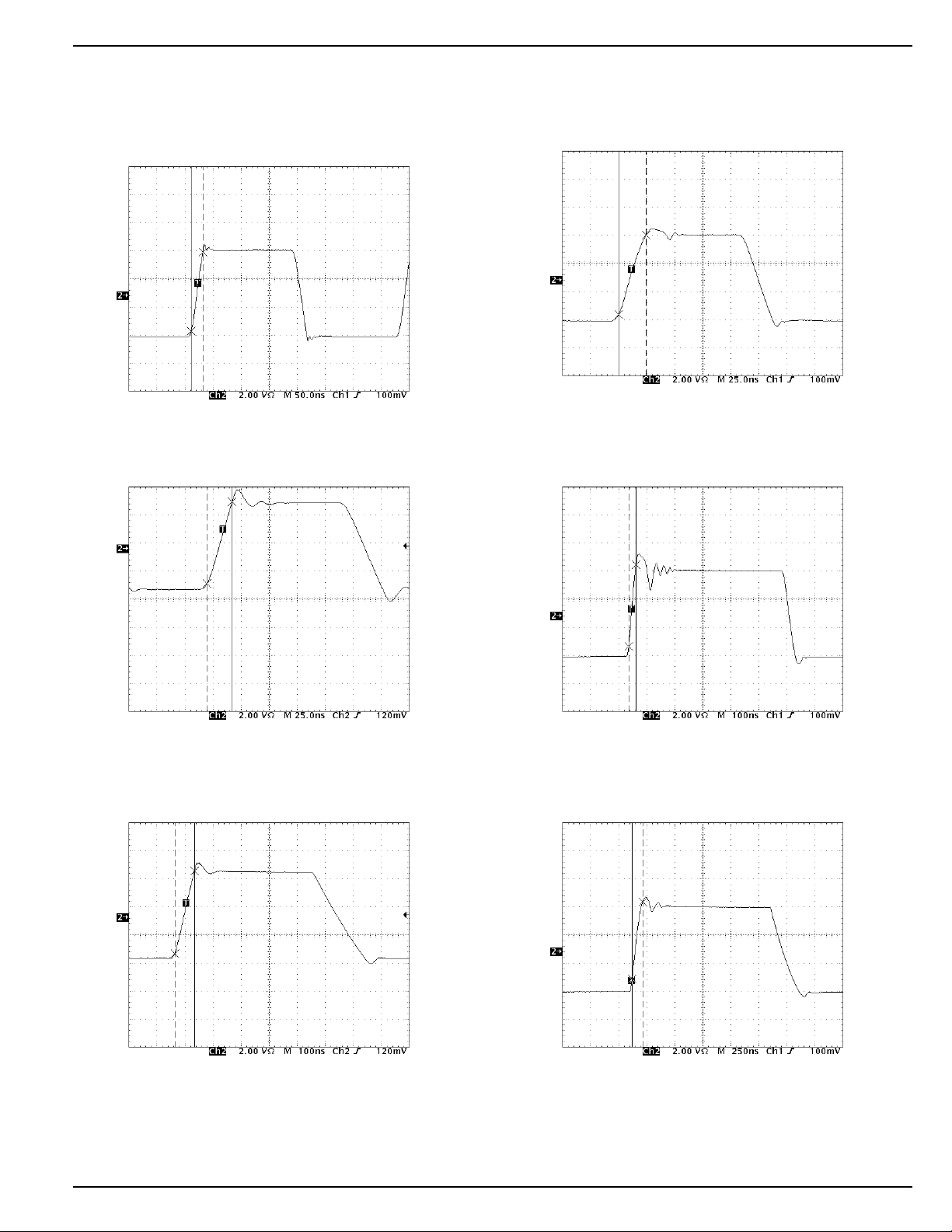
Large-Signal
Large-Signal
Pulse Response
VCC = ±9V
A
C
= 1
V
= 1.7pF
L
Pulse Response
VCC = ±5V
= 1
A
V
= 1.7pF
C
L
OUTPUT
OUTPUT
∆V = 5.64V
∆t = 21ns
Large-Signal
Pulse Response
∆V = 5.84V
∆t = 22.5ns
VCC = ±9V
= 1
A
V
= 100pF
C
L
OUTPUT
OUTPUT
∆V = 5.68V
∆t = 24.5ns
Large-Signal
Pulse Response
∆V = 5.84V
∆t = 26ns
VCC = ±5V
= 1
A
V
= 100pF
C
L
OUTPUT
Large-Signal
Pulse Response
∆V = 5.88V
∆t = 70ns
VCC = ±9V
= 1
A
V
= 1000pF
C
L
OUTPUT
Large-Signal
Pulse Response
VCC = ±5V
A
C
∆V = 5.48V
∆t = 95ns
= 1
V
= 1000pF
L
September 2000 9 Rev 8/00-A MIC915
Page 10

MIC915 Micrel
PVVI
DVV
S
(noload)
=−
()
+−
TotalPower Dissipation P P
DDt
=+
(noload) (outpu stage)
Max AllowablePowerDissipation
TT
W
JA
. =
−
(max) (max)
TBD
Applications Information
The MIC915 is a high-speed, voltage-feedback operational
amplifier featuring very low supply current and excellent
stability. This device is unity gain stable and capable of
driving high capacitance loads.
Driving High Capacitance
The MIC915 is stable when driving any capacitance (see
“Typical Characteristics: Gain Bandwidth and Phase Margin
vs. Load Capacitance”) making it ideal for driving long coaxial
cables or other high-capacitance loads.
Phase margin remains constant as load capacitance is
increased. Most high-speed op amps are only able to drive
limited capacitance.
Note: increasing load capacitance does reduce the
speed of the device (see “Typical Characteristics: Gain Bandwidth and Phase Margin vs.
Load”). In applications where the load capacitance reduces the speed of the op amp to an
unacceptable level, the effect of the load capacitance can be reduced by adding a small resistor
(<100Ω) in series with the output.
Feedback Resistor Selection
Conventional op amp gain configurations and resistor selection apply, the MIC915 is NOT a current feedback device.
Resistor values in the range of 1k to 10k are recommended.
Layout Considerations
All high speed devices require careful PCB layout. The high
stability and high PSRR of the MIC915 make this op amp
easier to use than most, but the following guidelines should
be observed: Capacitance, particularly on the two inputs pins
will degrade performance; avoid large copper traces to the
inputs. Keep the output signal away from the inputs and use
a ground plane.
It is important to ensure adequate supply bypassing capacitors are located close to the device.
Power Supply Consideration
Regular supply bypassing techniques are recommended. A
10µF capacitor in parallel with a 0.1µF capacitor on both the
positive and negative supplies are ideal. For best performance all bypassing capacitors should be located as close to
the op amp as possible and all capacitors should be low ESL
(equivalent series inductance), ESR (equivalent series resistance). Surface-mount ceramic capacitors are ideal. Both V–
pins must be externally shorted together.
Thermal Considerations
It is important to ensure the IC does not exceed the maximum
operating junction (die) temperature of 85°C. The part can be
operated up to the absolute maximum temperature rating of
125°C, but between 85°C and 125°C performance will degrade, in particular CMRR will reduce.
A MIC915 with no load, dissipates power equal to the quiescent supply current * supply voltage
When a load is added, the additional power is dissipated in
the output stage of the op amp. The power dissipated in the
device is a function of supply voltage, output voltage and
output current.
PVVI
DV
(outputstage)
=−
()
+
OUT OUT
Ensure the total power dissipated in the device is no greater
than the thermal capacity of the package. The MSOP-10
package has a thermal resistance of TBD°C/W.
MIC915 10 September 2000
Page 11

MIC915 Micrel
Package Information
3.15 (0.122)
2.85 (0.114)
0.30 (0.012)
0.15 (0.006)
0.50 BSC (0.020)
4.90 BSC (0.193)
3.10 (0.122)
2.90 (0.114)
1.10 (0.043)
0.94 (0.037)
0.15 (0.006)
0.05 (0.002)
MSOP-10
6° MAX
0° MIN
DIMENSIONS:
MM (INCH)
0.26 (0.010)
0.10 (0.004)
0.70 (0.028)
0.40 (0.016)
September 2000 11 Rev 8/00-A MIC915
Page 12

MIC915 Micrel
MICREL INC. 1849 FORTUNE DRIVE SAN JOSE, CA 95131 USA
TEL + 1 (408) 944-0800 FAX + 1 (408) 944-0970 WEB http://www.micrel.com
This information is believed to be accurate and reliable, however no responsibility is assumed by Micrel for its use nor for any infringement of patents or
other rights of third parties resulting from its use. No license is granted by implication or otherwise under any patent or patent right of Micrel Inc.
© 2000 Micrel Incorporated
MIC915 12 September 2000
 Loading...