

Page 1

KA3080/KA3080D/KA3080DM
3-Phase BLDC Motor Driver
www.fairchildsemi.com
Features
• 3-Phase, Full-Wave, Linear BLDC Motor Driver With 3
Hall Sensors
• Built-in TSD (Therml Shutdown) Circuit
• Built-in Torque Ripple Control Circuit
• Built-in Output Current Limiter
• Motor Speed Contro l
•High Output Current
• Built-in FG Amplifier With Sinusoidal Waveforms
• Built-in Hall Amplifier
• Built-in CW and CCW Circuit
Description
The KA3080 , KA3080D, KA3080DM are a monolithic
integrated circuit, and it is suitable for 3-phase capstan motor
driver for VCR system.
32-SDIPH-400 28-SSOPH-375
28-SSOPH-375SG2
Target Application
• Video Cassette Recorder (VCR) Capstan Motor
• Other 3-Phase BLDC Motor
©2002 Fairchild Semiconductor Corporation
Ordering Information
Device Package Operating Temp.
KA3080C 32-SDIPH-400 -25°C ~ +75°C
KA3080BD 28-SSOPH-375 -25°C ~ +75°C
KA3080BDTF 28-SSOPH-375 -25°C ~ +75°C
KA3080BD3 28-SSOPH-375SG2 -25°C ~ +75°C
KA3080BD3TF 28-SSOPH-375SG2 -25°C ~ +75°C
Rev. 1.0.2
Page 2

KA3080/KA3080D/KA3080DM
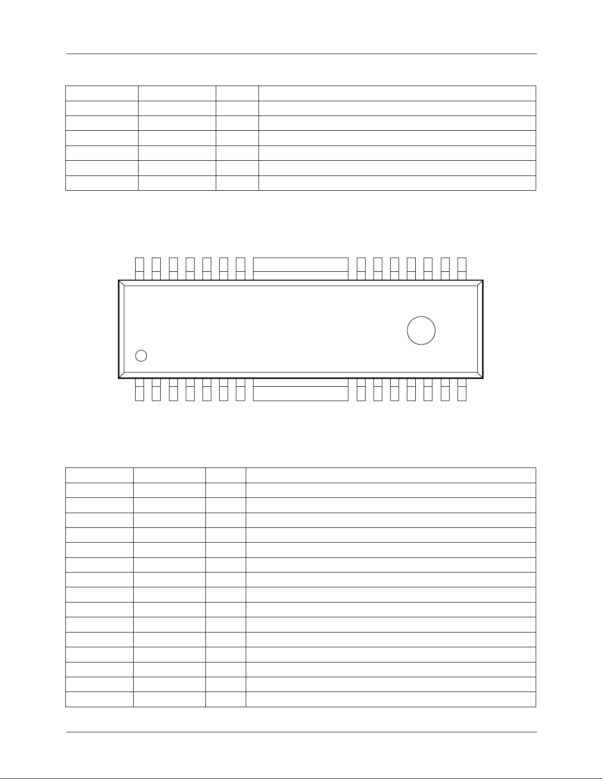
Pin Assignments (32SDIPH)
CTL
F/R
32 31 30 29 28 27 26 25 24 23 22 21 20 19 18 17
OUT2FGOUT1FGIN2FGIN1
CTL
TR
FG
GND
NC
REFVCTL
V
KA3080
U+
W+
W−
GND
RS
OUTUOUTVOUTWOUT
G
V−
V+
U−
Pin Definitions (32SDIPH)
Pine Number Pin Name I/O Pin Function Description
1 U+ I U+ Hall Signal Input
2 U- I U- Hall Signal Input
3 V+ I V+ Hall Signal Input
4 V- I V- Hall Signal Input
5 W+ I W+ Hall Signal Input
6 W- I W- Hall Signal Input
7 GND - Ground (Signal)
8 GND - Ground (Signal)
9 GND - Ground (Signal)
10 GND - Ground (Signal)
11 RS O Output Current Detection
12 G
13 U
14 V
15 W
16 V
17 V
OUT
OUT
OUT
OUT
CC2
CC1
18 CI - Phase Stabilization
19 I
20 V
21 V
LIM
CTL
REF
22 NC - No Connection
23 GND - Ground (Signal)
24 GND - Ground (Signal)
25 GND - Ground (Signal)
26 GND - Ground (Signal)
- Ground (Power)
OU Out
OV Out
OW Out
- Supply Voltage (Power)
- Supply Voltage(Signal)
I Current Limitation
I Voltage Control
I Voltage Control Reference
LIM
I
CC1
V
CI
16151413121110987654321
CC2
V
2
Page 3
KA3080/KA3080D/KA3080DM
Pin Definitions (32-SDIPH)
(Continued)
Pine Number Pin Name I/O Pin Function Description
27 FG
28 FG
29 F G
30 F G
31 TR
32 F/R
IN1
IN2
OUT1
OUT2
CTL
CTL
I FG Amp. Input1
I FG Amp. Input2
O FG Amp. Output
O FG Comp. Output
I Troque Ripple Control
I Forward & Reverse Control
Pin Assignments (28-SSOPH)
OUT
OUT
W
V
28 27 26 25 24 23 22 21 20 19 18 17 16 15
OUT
OUT
G
U
NC
NC
RS
FIN
GND
W+
V−
W−
KA3080D
V+
U−
U+
FIN
CC2VCC1
V
CI
LIM
CTL
I
V
NC
REF
V
GND
IN1FGIN2
FG
OUT1
FG
Pin Definitions (28-SSOPH)
Pine Number Pin Name I/O Pin Function Description
1V
2V
CC2
CC1
3 CI - Phase Stabilization
4I
5V
6V
LIM
CTL
REF
7 NC - No Connection
8 GND - Ground (Signal)
9FG
10 FG
11 FG
12 FG
13 TR
14 FR
IN1
IN2
OUT1
OUT2
CTL
CTL
15 U+ I U+ Hall Signal Input
- Supply Voltage (Power)
- Supply Voltage (Signal)
I Current Limitation
I Voltage Control
I Voltage Control Reference
I FG Amp. Input 1
I FG Amp. Input 2
O FG Amp. Output
O FG Comp. Output
I Torque Ripple Control
I Forward & Reverse Control
OUT2
FG
1413121110987654321
CTLFRCTL
TR
3
Page 4

KA3080/KA3080D/KA3080DM
Pin Definitions (28-SSOPH)
(Continued)
Pine Number Pin Name I/O Pin Function Description
16 U- I U- Hall Signal Input
17 V+ I V+ Hall Signal Input
18 V- I V- Hall Signal Input
19 W+ I W+ Hall Signal Input
20 W- I W- Hall Signal Input
21 GND - Ground (Signal)
22 RS O Output Current Detection
23 NC - No Connection
24 NC - No Connection
25 G
26 U
27 V
28 W
OUT
OUT
OUT
OUT
- Ground (Power)
OU Out
OV Out
OW Out
Internal Block Diagram (32-SDIPH)
CTL
F/R
32 31 30 29 28 27 24 23 22 21 20 19 18 17
CW & CCW
+
−
U+
TR
U−
OUT2FGIOUT1
CTL
FG
−
+
TSD
+
−−
V+
IN2FGIN1
FG
2.5V
−
+
+
V−
W+
W−
GND
26 25
LOGIC
GND
GND
GND
GND
GND
GND
GND
NC
RS
REF
V
−
+
OUT
G
CTL
LIM
V
I
1.25V
−
+
−
++
OUTVOUTWOUT
U
CC1
CI
V
16151413121110987654321
CC2
V
4
Page 5

Internal Block Diagram (28-SSOPH)
KA3080/KA3080D/KA3080DM
OUT
OUT
W
V
1234567 8
CC2VCC1
V
OUT
OUT
U
G
NC
NC
RS
FIN
LOGIC
−
++
1.25V
LIM
I
+ −
CTL
REF
V
V
+ −
CI
2.5V
FIN
NC
GND
1.8k
GND
W−
W+
−
+
IN1
FG
−
+
IN2
FG
+
−
56k
91011121314
V−
−
+
TSD
OUT1FGOUT2
FG
V+
1516171819202122232425262728
−
+
CW&CCW
CTLFRCTL
TR
U+
U−
5
Page 6

KA3080/KA3080D/KA3080DM
Equivalent Circuits (32-SDIPH: Ο, 28-SSOPH: (#))
Description Pin No. Internal Circuit
32-SDIPH
1, 2, 3
4, 5, 6
Hall Input
Output &
Current Detection
28-SSOPH
15, 16, 17
18, 19, 20
32-SDIPH
13, 14, 15, 11
28-SSOPH
26, 27, 28, 22
(15)
(17)
(19)
1
3
5
Vcc1
RS (0.5Ω)
16
(1) V
CC2
13
11
(22 Pin)
(26) U
14
2
4
6
OUT
12
(16)
(18)
(20)
(27) V
15
(25 Pin)
OUT
(28) W
OUT
Speed Control
(Current limitation)
6
32-SDIPH
19
28-SSOPH
4
(4)
Vcc1
19
Page 7

KA3080/KA3080D/KA3080DM
Equivalent Circuits (32-SDI PH: Ο , 28-SSOPH: (#))
Description Pin No. Internal Circuit
32-SDIPH
Speed Control
(Voltage Control)
Voltage Control
Reference
20
28-SSOPH
5
32-SDIPH
21
28-SSOPH
6
(6Pin)
(5Pin)
20
21
(Continued)
V
CC1
Vcc1
11
R
S
G
OUT
(22Pin)
Torque Ripple
Control
Forward & Reverse
Control
32-SDIPH
31
28-SSOPH
13
32-SDIPH
32
28-SSOPH
14
Vcc1
R
31
S
(13Pin)
Vcc1
32
1.25V
7
Page 8

KA3080/KA3080D/KA3080DM
Equivalent Circuits (32-SDI PH: ΟΟΟΟ , 28-SSOPH: (#))
Description Pin No. Internal Circuit
FG AMP.
Phase
Stabilization
32-SDIPH
27, 28, 29, 30
28-SSOPH
9, 10, 11, 12
32-SDIPH
16, 18
28-SSOPH
1, 3
30
(12Pin)
−
+
FG COMP
29
(11Pin)
(Continued)
FG AMP
+
−
CI
27
(9Pin)
2.5V
28
(10Pin)
1618
(1Pin)(3Pin)
8
Page 9

KA3080/KA3080D/KA3080DM
Absolute Maximum Ratings (Ta=25°°°°C)
Parameter Symbol Value Unit Remark
Supply Voltage (Signal) V
Supply Voltage (Power) V
Maxium Output Current I
Power Dissipation P
Junction Temperature T
CC1max
CC2max
Omax
d
J
OPR
Storage Temperature T
STG
Note:
1. Duty 1 / 100, pulse wid th 500µs
2. 1) When mounted on glass epoxy PCB (76.2 × 114 × 1.57mm)
2) Power dissipation reduces 13.6mW / °C for using above Ta=25°C. (32SDIPH Type)
Power dissipation reduces 19.2mW / °C for using ab ove Ta=25°C. (28SSOPH Type)
Power dissipation reduces 20.0mW / °C for using ab ove Ta=25°C. (28SSOPH -SG2 Type)
3) Do not exceed Pd and SOA(Safe Operating Area).
7V -
28 V -
note1
1.5
2.4
1.7
2.5
note2
note2
note2
A / Phase V
CC1
=5V, V
W 32SDIPH-400
W 28SSOPH-375
W 28SSOPH-375SG2
150 °C
-25 ~ +75 °C
V
CC1
=5V, V
-40 ~ +125 °C
CC2
CC2
=16V
=16VOperating Temperature T
Power Dissipation Curve
Power dissipation (W)
2.5
2.4
1.7
0
2
8
-
S
S
O
3
2
2
8
25 75 150
P
H
I
P
SOA
S
O
-
3
7
5
H
P
S
G
2
H
-
3
7
5
Ambient temperature, Ta [°C]
S
D
-
S
Recommened Operating Conditions (Ta=25°°°°C)
Parameter Symbol Value Unit
Operating Supply Voltage (Signal) V
Operating Supply Voltage (Power) V
CC1
CC2
4.5 ~ 5.5 V
8 ~ 27 V
9
Page 10

KA3080/KA3080D/KA3080DM
Electrical Characteristics
(V
=5V, V
CC1
Block Parameter Symbol Conditions Min. Typ. max. Unit
Total
Output
Control
Rotation
Control
FG amp
& comp
=16V, RS=0.5Ω, Ta=25°C, unless otherwise specified)
CC2
Quiescent Input Current 1 I
Quiescent Input Current 3 I
Quiescent Input Current I
Quiescent Input Current (Max.) I
CC1
CC3
O1
O3
Current Limit Level GM
Control Gain GM
Output Amp. Saturation Voltage 4
(Outflow Current)
Output Amp. Saturation Voltage 4
(Inflow Current)
V
SU4IOUT
V
SD4IOUT
Limit Current Gap Of Phases LD1 LI
Current Gap Of Phases D1 I
L1
1
V
=5V, VFR=5V 5.0 8.5 12.0 mA
CC1
V
=7V, VFR=5V 6.0 10.0 15.0 mA
CC1
V
=16V, V
CC2
V
=27V, V
CC2
RS=0.5Ω
VIN=0V
=0V - 1.5 5.0 mA
LIM
LIM=VREF
-2.77.0mA
32-SDIPH 0.61 0.67 0.73
28-SSOPH 0.46 0.52 0.58
32-SDIPH 0.9 1.0 1.1
28-SSOPH 0.7 0.8 0.9
=0.8A / Phase - 1.8 2.0 V
=0.8A / Phase - 1.8 2.0 V
-LI
VU2
VU1-IWU1
WU2
-20 0 20 mA
-20 0 20 mA
Phase Output Wave Frequency 1 PF1 15kHz, 5Vp-p 2.45 2.5 2.55 kHz
Phase Output Wave Frequency 4 PF4 10kHz, 5Vp-p 1.62 1.67 1.72 kHz
Current Limit Input Current I19 - - 350 2000 nA
Control Input Current I20 - - 350 2000 nA
Input Offset Voltage U V
CW Voltage Range V
O2U
FRU
--50050mV
- 1.0 1.3 1.6 V
FG Amp. Input DC Voltage V28(10) 32-SDIPH (28-SSOPH) 2.2 2.5 2.8 V
FG Amp. Reference Voltage V27(9) 32-SDIPH (28-SSOPH) 2.2 2.5 2.8 V
FG Amp. Voltage Gain FG
FG Comp. Output Frequency F
FG Comp Downward Input
Threshold Voltage
FG Comp. UPward Input
Threshold Voltage
COMP
V
THDW
V
THUP
FG Comp. Hysteresis V
FG Output High Voltage FG
FG Output Low Voltage FG
HYS
AV1
HI
LO
FG
=10kHz, 60mVp-p 28 31 34 Times
IN3
FG
FG
FG
=3Vp-p (1kHz) 0.9 1 1.1 kHz
AMP0
=3→2 Sweep 2.40 2.45 2.50 V
AMP0
=2→3 Sweep 2.50 2.55 2.60 V
AMP0
- 20 100 180 mV
FG
=3V 4.2 - - V
IN3
FG
=2V - - 0.4 V
IN3
A / V
A / V
10
Page 11

KA3080/KA3080D/KA3080DM
Application Information (32-SDIPH: ΟΟΟΟ , 28-SSOPH: (#))
1. Hall Input
The input signal of the hall sensor requires larger amplitude than 100mVo-p. The operating voltage level of the hall sensor is
from 1.2V ~ V
CC1
-0.8V.
VCC1
(15)
1
(17)
3
5
(19)
2. Output Current Detection
(16)
2
(18)
4
6
(20)
(1) V
16
CC2
(26) U
13
OUT
(27) V
14
15
More than 1.7V
More than 100mVo-p
More than 1.3V
OUT
(28) W
OUT
RS (0.5Ω)
The RS (Output current sensing resistor ) is connected to G
OUT
which is feedback amplifier.
3. Motor Speed Control (Input Current Limitation)
The maxmum output current is limitted by the I
If current limitation is not in use then connect it to V
The control gain is approx. 0.67A/V as follows.
GML = ∆I
O
/ ∆V
LIM
= (I
O2
− I
O1
) / (V
LIM2
(Current limiting) voltage.
LIM
.
CC1
LIM1
), where V
− V
11
(22 Pin)
12
(25 Pin)
and Approx. 0.5Ω, It converts motor current to a voltage
= 1.45V → Output current=I
V
LIM1
= 1.55V → Output current=I
LIM2
O1
O2
11
Page 12

KA3080/KA3080D/KA3080DM
(4)
19
Output
Current
(Max.)
0.67A/V
4. Motor Speed Control (Input Voltage Control)
Motor speed control is possible when V
The control gain is approx. 1.0A/V as follows.
GML = ∆I
V
O
/ ∆V
CTL
= (I
(5Pin)
O2
) / (V
− I
O1
20
CTL
CTL2
V
CC1
≥ V
G
OUT
− V
REF
CTL1
.
), where V
REF
REF
Output
Current
(Max.)
01.25V V
= 2.5V, V
= 2.5V, V
0V
= 2.6V → Output current=I
CTL1
= 2.7V → Output current=I
CTL2
REF
1.0A/V
LIM
O1
O2
V
LIM
5. Voltage Control Reference
The input voltage range is 2V ≤ V
12
REF
≤ (V
CC1
(6Pin)
- 2V).
21
(22Pin)
11
R
S
Page 13

6. Torque Ripple Control
KA3080/KA3080D/KA3080DM
V
CC1
1
2
R
31
S
3
(13Pin)
The motor torque ripple is controlled by the TR
CTL
1. GND
2. Normal Mode
3. Control Mode
7. Forward & Reverse Rotation Control
32
(14Pin)
Forward mode: V
Reverse mode: V
FRCTL
FRCTL
≥ 1.8V
≤ 0.8V
8. FG Amp
(12Pin)
30
−
+
FG COMP
(Torque ripple control) voltege as follows.
1.25V
FG AMP
29
(11Pin)
+
−
2.5V
27
28
(9Pin)
(10Pin)
9. Phase Stabilization
CI
Be inserted a capacitor between V
This capacitor, approx. 0.1µF is for the phase stabilization of the circuit.
CC2
.
1618
(1Pin)(3Pin)
13
Page 14

KA3080/KA3080D/KA3080DM
Timming Chart
FR
U (+)
U
U (−)
V (+)
V
V (−)
W (+)
forward mode
CTL
(CW): High
FR
CTL
(CCW): Low
reverse mode
W
W (−)
+
U
OUT
−
+
V
OUT
−
+
W
OUT
−
0 180 360 540 720
ωt
0 180 360 540 720
OUTFLOW
INFLOW
ωt
14
Page 15

Test Circuits (32-SDIPH)
R3=10k R2=1k R1=10k
KA3080/KA3080D/KA3080DM
V
FR
V1
V2
V3
V4
V5
V6
V
R4=0.5(20W)
C1=C2=C3=0.1µF
I
CC1
=16V
CC2
M
M
M
M
M
M
A
SW7
R5=R6=R7=5(20W)
A
A
A
0.01µF
H
L
H
L
H
L
H
L
H
L
H
L
SW8
SW9
SW10
SW1
SW2
SW3
SW4
SW5
SW6
10µF
1
U+
2
U−
3
V+
V−
4
W+
5
W−
6
GND
7
8
GND
FG
FG
F/R
TR
OUT2
OUT1
FG
FG
GND
GND
CTL
CTL
IN2
IN1
32
31
30
29
28
27
26
25
KA3080
GND
9
10
GND
RS
11
12
G
OUT
13
U
OUT
V
OUT
14
15
W
OUT
16 17
V
CC2
0.1µF
GND
GND
V
REF
V
CLT
I
V
CC1
NC
LIM
24
23
22
21
20
19
18
CI
SW14
SW11
V
LIM
1
2
1µF
1µF
R9=1k
SW16
1
3
3
1
FG
FG
FG
CTL
(VCTL)
SW13
3
2
OUT2
OUT1
2
2
1
SW15
2
FG
FG
1
SW12
R10=1k
IN2
IN1
R8=1k
10M
10M
V
CC1
V
CTL
10M
=5V
I
CC2
15
Page 16

KA3080/KA3080D/KA3080DM
Test Circuits (28-SSOPH)
LIM
CTL
C7
0.01µC410µ
1
V
CC2
W
OUT
28
SW10
2
1µ
1
SW12
2
3
SW13
2
1
SW16
3
4
5
6
7
V
CI
I
LIM
V
V
NC
CC1
CTL
REF
V
OUT
U
OUT
G
OUT
NC
NC
RS
27
SW9
26
SW8
25
24
23
22
R7=R8=R9=5(20W)
A
C3
A
C2
A
A
R8
R9
R4
0.5(20W)
=16V
V
CC2
I
CC1
=5V
V
CC1
I
CC1
V
10M
10M
V
SW7
R8
1k
R9
1k
FIN FIN
KA3080D
FG
FG
IN1
IN2
V
C6
1µ
+
1
SW11
3
2
8
9
10
GND
FG
FG
IN1
IN2
GND
W−
W+
+
C5
FG
OUT1
1µ
R10
FG
2
3
2
1
SW15
OUT2
1k
FR
1
11
12
3
13
SW14
14 15
FG
FG
TR
FR
OUT1
OUT2
CTL
CTL
V−
V+
U−
U+
21
H
SW1
20
SW2
19
SW3
18
SW4
17
SW5
16
SW6
M
L
H
M
L
H
M
L
H
M
L
H
M
L
H
M
L
R1
10kR21kR310k
V6
V5
V4
V3
V2
V1
16
Page 17

Typical Application Circuits (32-SDIPH)
V
=5V
CC1
(SIGNAL)
180k
KA3080/KA3080D/KA3080DM
180k
LU
LV
HU
HV
HW
0.5k
U+
1
U−
2
V+
3
V−
4
5
W+
6
W−
GND
7
8
GND
FG
FG
F/R
TR
OUT2
OUT1
FG
FG
GND
GND
CTL
CTL
IN2
IN1
32
F/R
7.5k
31
OUTPUT
FGA
FGA
FG
FG
MP
MP
AMP
AMP
INPUT1
30
29
28
27
OUTPUT
INPUT 2
2
1
26
25
KA3080
GND
9
10
GND
RS
11
G
12
OUT
U
OUT
13
V
OUT
14
GND
GND
V
REF
V
CTL
I
NC
LIM
24
23
22
10k
21
10k
20
19
V
CTL
I
LIM
V
=16V
CC2
(POWER)
LW
+
10µF
W
15
OUT
16 17
V
cc2
CI
V
cc1
104
18
V
=5V
CC2
(SIGNAL)
17
Page 18

KA3080/KA3080D/KA3080DM
Typical Application Circuits (28-SSOPH)
V
=16V
CC2
(POWER)
=5V
V
CC1
(SIGNAL)
V
CTL
INPUT
10k
10k
1
2
3
4
5
6
7
FIN FIN
V
V
CI
I
LIM
V
V
NC
CC2
CC1
CTL
REF
KA3080D
W
OUT
V
OUT
U
OUT
G
OUT
NC
NC
RS
28
27
26
25
24
23
22
10µ
0.5(20W)
0.1µ 0.1µ
0.1µ
L
W
L
V
L
U
GND
(POWER)
GND
(SIGNAL)
FG AMP
INPUT1
FG AMP
INPUT2
FG AMP
OUTPUT1
FG AMP
OUTPUT2
TR
CTL
INPUT
FR
CTL
INPUT
8
9
10
11
12
13
14 15
GND
FG
FG
FG
FG
TR
FR
IN1
IN2
OUT1
OUT2
CTL
CTL
GND
W−
W+
V−
V+
U−
U+
21
20
H
W
180k
19
18
H
V
17
16
H
U
180k
18
Page 19

KA3080/KA3080D/KA3080DM
19
Page 20

KA3080/KA3080D/KA3080DM
DISCLAIMER
FAIRCHILD SEMICONDUCTOR RESERVES THE RIGHT TO MAKE CHANGES WITHOUT FURT HER NOTICE TO ANY
PRODUCTS HEREI N TO IMPROVE RELIABILITY, FUNCTIO N OR DESIGN. FAIRCH IL D DOES NOT ASSUME ANY
LIABILITY ARISING OUT OF THE APPLICATION OR USE OF ANY PRODUCT OR CIRCUIT DESCRIBED HEREIN; NEITHER
DOES IT CONVEY ANY LICENSE UNDER IT S PATENT RIGHTS, NOR THE RIGHTS OF OTHE RS.
LIFE SUPPORT POL I CY
FAIRCHILD’S PR ODUCTS ARE NOT AUTH ORIZED FOR USE AS C RITICAL COMPONENT S IN LIFE SUPPORT DE VICES
OR SYSTEMS WITHOUT THE EXPRESS WRITTEN APPROVAL OF THE PRESIDENT OF FAIRCHILD SEMICONDUCTOR
CORPORATION. As used herein :
1. Life support devices or systems are devices or systems
which, (a) are intended for surgical implant into the body,
or (b) support or sustain life, and (c) whose failure to
perform when properly used in accordance with
2. A critical component in any component of a life support
device or sy stem whose fai lure to perform can be
reasonably expec ted to cause the failur e of the life support
device or system, or to affect its safety or effec t iv ene ss .
instructions for use provided in the labeling, can be
reasonably expected to result in a significant injury of the
user.
www.fairchildsemi.com
9/6/02 0.0m 001
2002 Fairchild Semiconductor Corporation
Stock#DSxxxxxxxx
 Loading...