

Page 1
©2000 Fairchild Semiconductor International
www.fairchildsemi.com
Rev. 1.0.1
February. 2000.
1
Features
• BTL (H-Bridge type linear) 4channel motor driver
• Wide dynamic range:
-SV
CC
=12V, PV
CC1
=5V, RL=8Ω → VOM=4.2V
-SV
CC
=12V, PV
CC2
=12V, RL=24Ω → VOM=10.4V
• Built in level-shift circuit
• Built in OP-amp for digital input
• Built in thermal shutdown (TSD) circuit
• Three independent sources
• Low crossover distortion
• Built-in reverse rotation prevented
• Built-in short breaker
Description
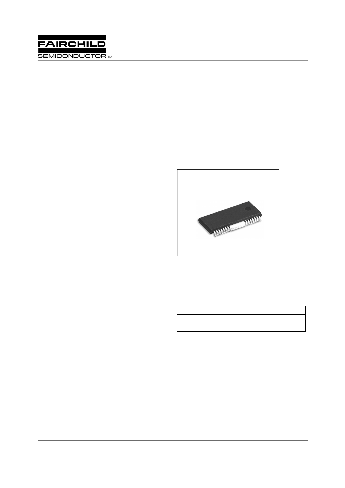
The KA3012D is a monolithic IC, and suitable for 4-CH
motor driver which drives sled motor, loading motor, focus
& tracking actuator of CD-media system and built in OPamp which can receive digital signal from servo of CDmedia system.
28-SSOPH-375
Typical Applications
• Compact disk ROM (CD-ROM)
• Compact dis k RW (CD-RW)
• Digital video disk ROM (DVD-ROM)
• Digital video disk RAM (DVD-RAM)
• Digital video disk player (DVDP)
• Other compact disk media
Ordering Information
Device Package Operating Temp.
KA3012D-02 28-SSOPH-375 -35 °C ~ 85 °C
KA3012D-02TF 28-SSOPH-375 -35 °C ~ 85 °C
KA3012D
4-Channel Motor Driver
Page 2
KA3012D
2
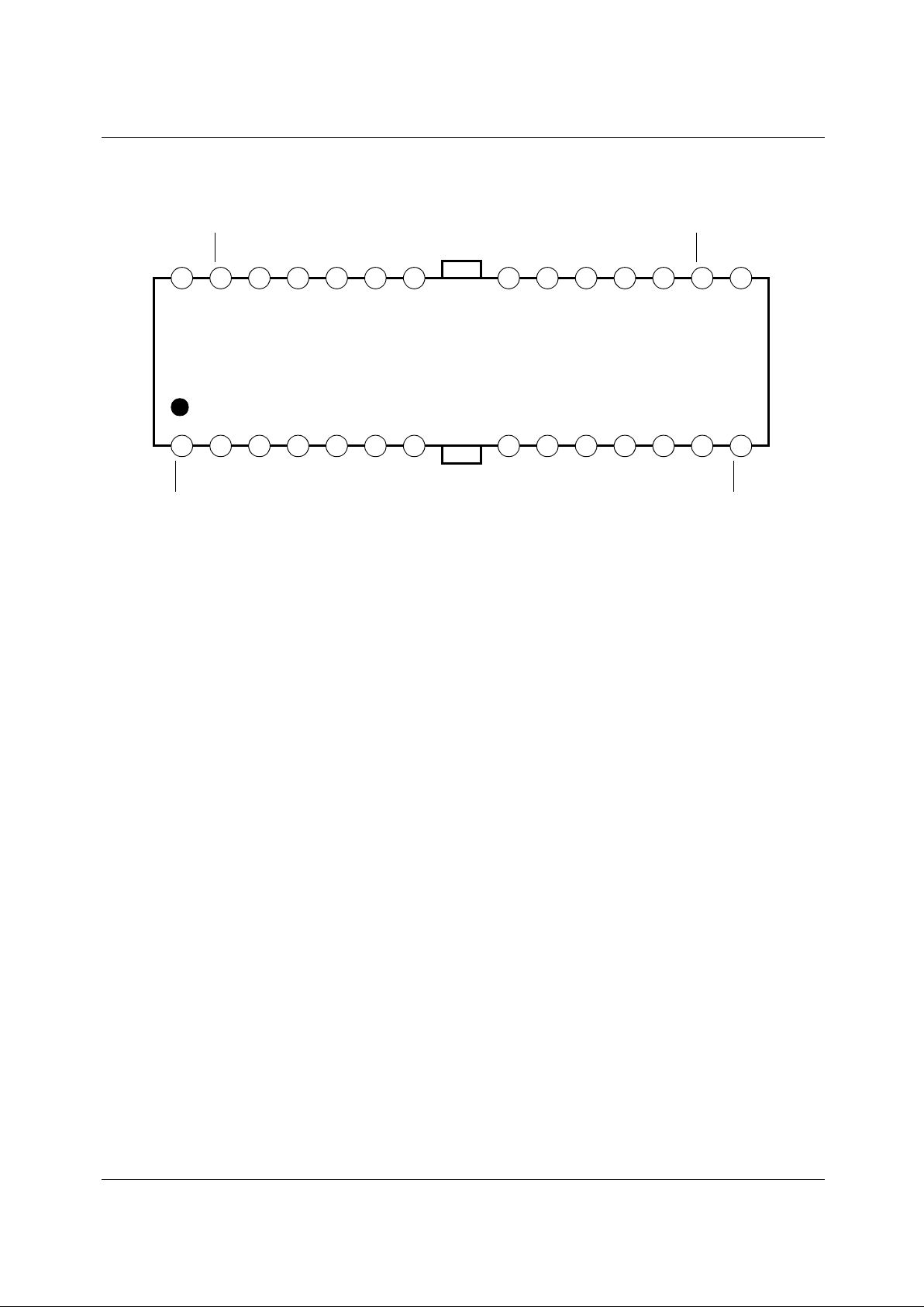
Pin Assignments
1234567 891011121314
1516171819202122232425262728
CH1-O
CH1-O
AMP1-O
AMP1-I (−)
AMP1-I (+)
BIAS
SVCC
GND
MUTE
AMP2-I (+)
AMP2-I (−)
AMP2-O
CH2-O
CH2-O
GND
CH4-O
CH4-O
AMP4-O
AMP4-I (−)
AMP4-I (+)
PVCC1
PVCC2
AMP3-I (+)
AMP3-I (−)
CH3-O
CH3-O
GND
FIN
(GND)
FIN
(GND)
KA3012D
AMP3-O
Page 3

KA3012D
3
Pin Definitions
Pin Number Pin Name I/O Pin Function Description
1 CH1-O O Drive CH 1 output (−)
2 CH1-O O Drive CH 1 output (+)
3 AMP1-O O Op-amp CH 1 output
4AMP1-I(−) I Op-amp CH 1 input (−)
5 AMP1-I(+) I OP-amp CH 1 input (+)
6 BIAS I Bias input
7 SVCC - Supply voltage (Signal)
8 GND - Ground
9MUTEIMute
10 AMP2-I(+) I OP-amp CH 2 input (+)
11 AMP2-I(−) I Op-amp CH 2 input (−)
12 AMP2-O O Op-amp CH 2 output
13 AMP2-O O OP-amp CH 2 output (+)
14 CH2-O O Op-amp CH 2 output
(Op-amp CH 2 output)
15 GND - Ground
16 CH3-O O Drive CH 3 output (−)
17 CH3-O O Drive CH 3 output (+)
18 AMP3-O O OP-amp CH 3 output
19 AMP3-I(−) I Drive CH 3 input (−)
20 AMP3-I(+) I Drive CH 3 input (+)
21 PVCC2 - Supply voltage (CH 2 & CH 3)
22 PVCC1 - Supply voltage (CH1 & CH 4)
23 AMP4-I(+) I OP-amp CH 4 input (+)
24 AMP4-I(−) I Op-amp CH 4 input (−)
25 AMP4-O O Op-amp CH 4 output
26 CH4-O O Drive CH 4 output (+)
27 CH4-O O Drive CH 4 output (−)
28 GND - Ground
Page 4
KA3012D
4
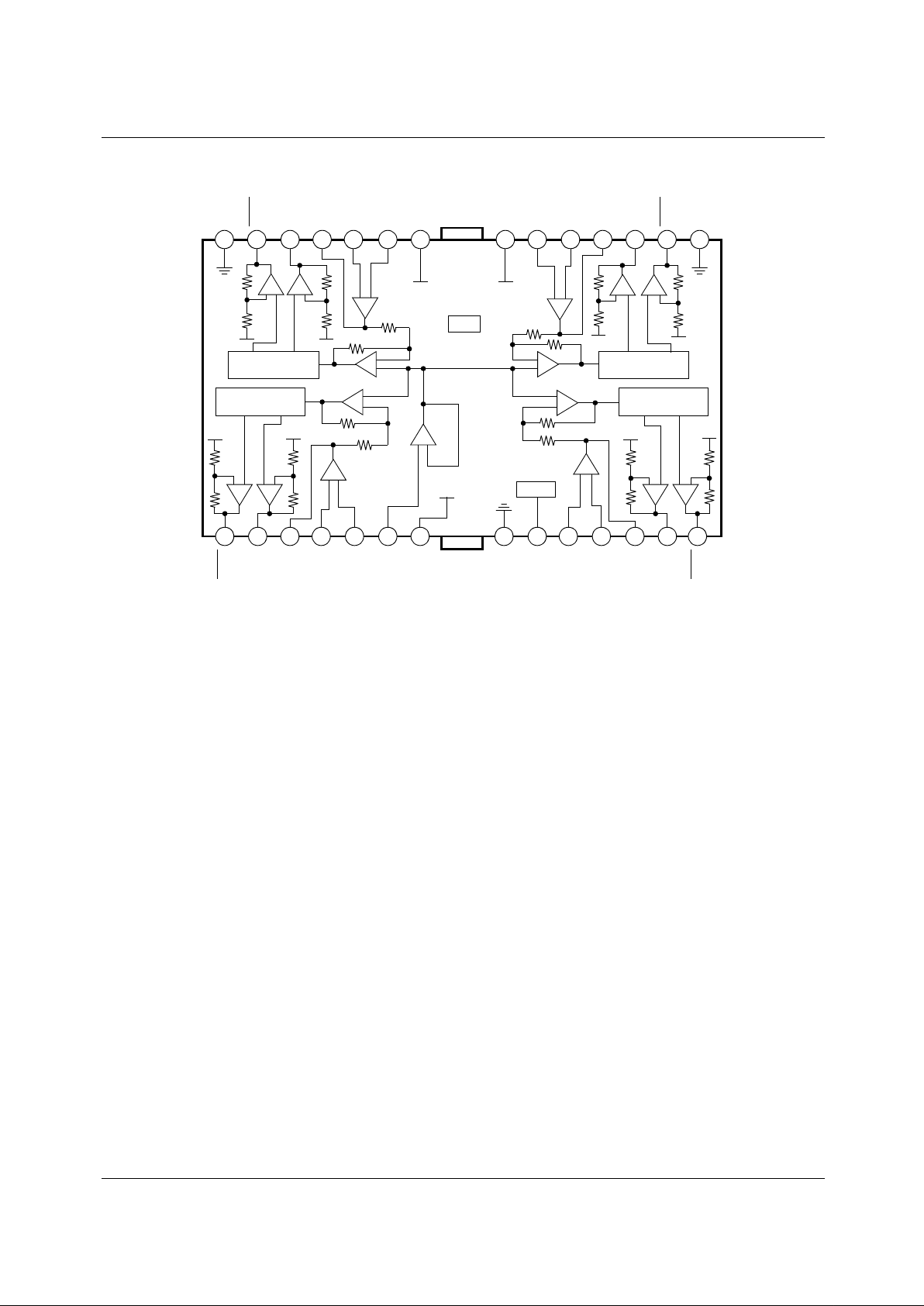
Internal Block Diagram
NOTE:
The drive channel outputs are determined pre OP-amp output.
1234567 891011121314
1516171819202122232425262728
10k
10k 10k
10k10k
10k
10k
10k
10k 10k
10k10k
10k 10k
10k10k
10k
20k
10k
20k
10k
10k10k
10k
GND
PV
CC1
/2
GND
MUTE
TSD
PV
CC2
/2
PV
CC2
/2
GND
SV
CC
PV
CC1
/2
PV
CC2
/2
PV
CC2
/2
PV
CC1
/2
+−+
−
−
+
+
−
+
−
− +
++
−−
+
−
LEVEL-SHIFT
−
+
LEVEL-SHIFT
−
+
−
+
+
−
−
+
+
−
LEVEL-SHIFT
+
−
LEVEL-SHIFT
−
++
−
+
−
++
−−
PV
CC2
PV
CC1
CH1-O
CH1-O
AMP1-O
BIAS
SVCC
GND
MUTE
AMP2-I (+)
AMP2-I (−)
AMP2-O
CH2-O
CH2-O
GND
CH3-O
CH3-O
AMP3-O
AMP3-I (−)
AMP3-I (+)
PVCC1
PVCC2
AMP4-I (+)
AMP4-I (−)
AMP4-O
CH4-O
CH4-O
GND
AMP1-I (−)
AMP1-I (+)
GND
GND
Page 5
KA3012D
5
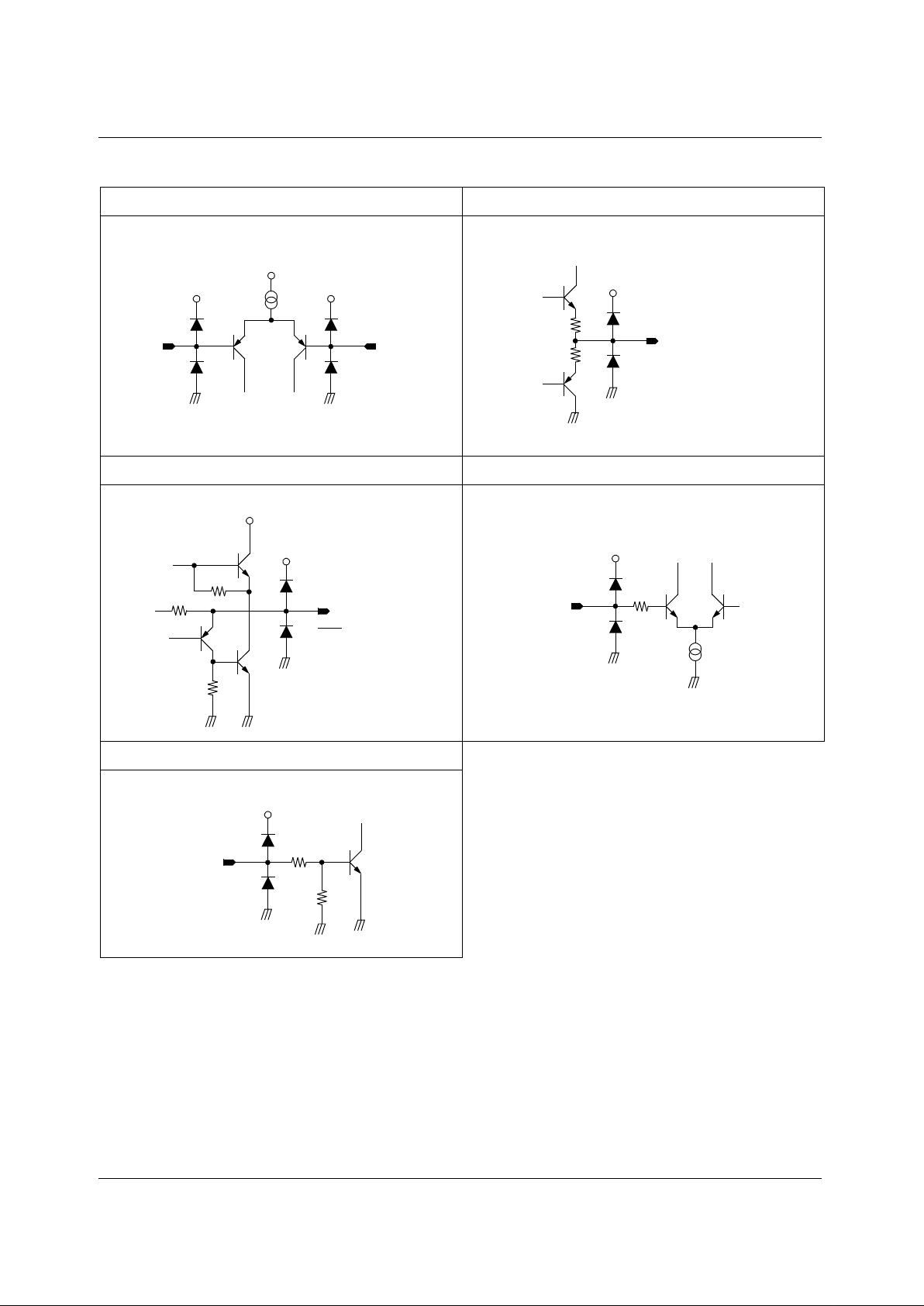
Equivalent Circuits
Op-amp input Op-amp output
Drive output Bias
Mute
AMP-I (−)AMP-I (+)
4, 11, 19, 24
Pin
5, 10, 20, 23
Pin
80Ω
80Ω
AMP-O
3, 12, 17, 25 Pin
10kΩ
10kΩ
1kΩ
CH-O
(2, 13, 17, 26 Pin)
CH-O
(1, 14, 16, 27 Pin)
200Ω
Bias
(6 Pin)
50k
50k
Mute
(9 Pin)
Page 6
KA3012D
6
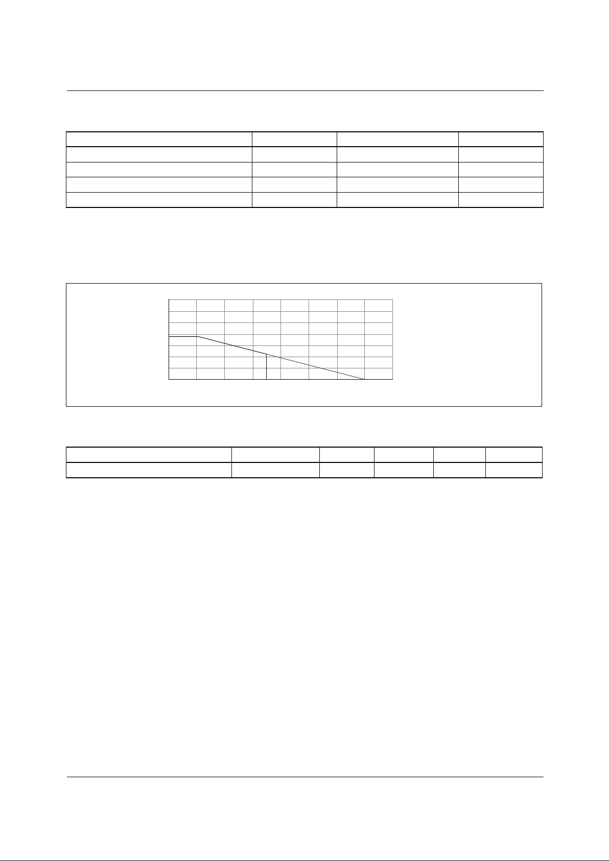
Absolute Maximum Rating (Ta = 25°C)
NOTE:
1. When mounted on 50mm × 50mm × 1mm PCB (Phenolic resin material).
2. Power dissipation reduces 13.6mW / °C for using above Ta=25°C.
3. Do not exceed P
D
and SOA (Safe operating area).
Power Dissipation Curve
Recommended Operating Condition (Ta = 25°C)
Parameter Symbol Value Unit
Supply voltage V
CC
15 V
Power dissipation P
D
1.7
note
W
Operating temperature range T
OPR
−35 ~ +85 °C
Storage temperature range T
STG
−55 ~ +150 °C
Parameter Symbol Min. Typ. Max. Unit
Supply voltage SV
CC
, V
CC1
,
V
CC2
4.5 - 13.2 V
3,000
2,000
1,000
0
0 25 50 75 100 125 150 175
Pd (mW)
Ambient temperature, Ta [°C]
SOA
85
Page 7
KA3012D
7
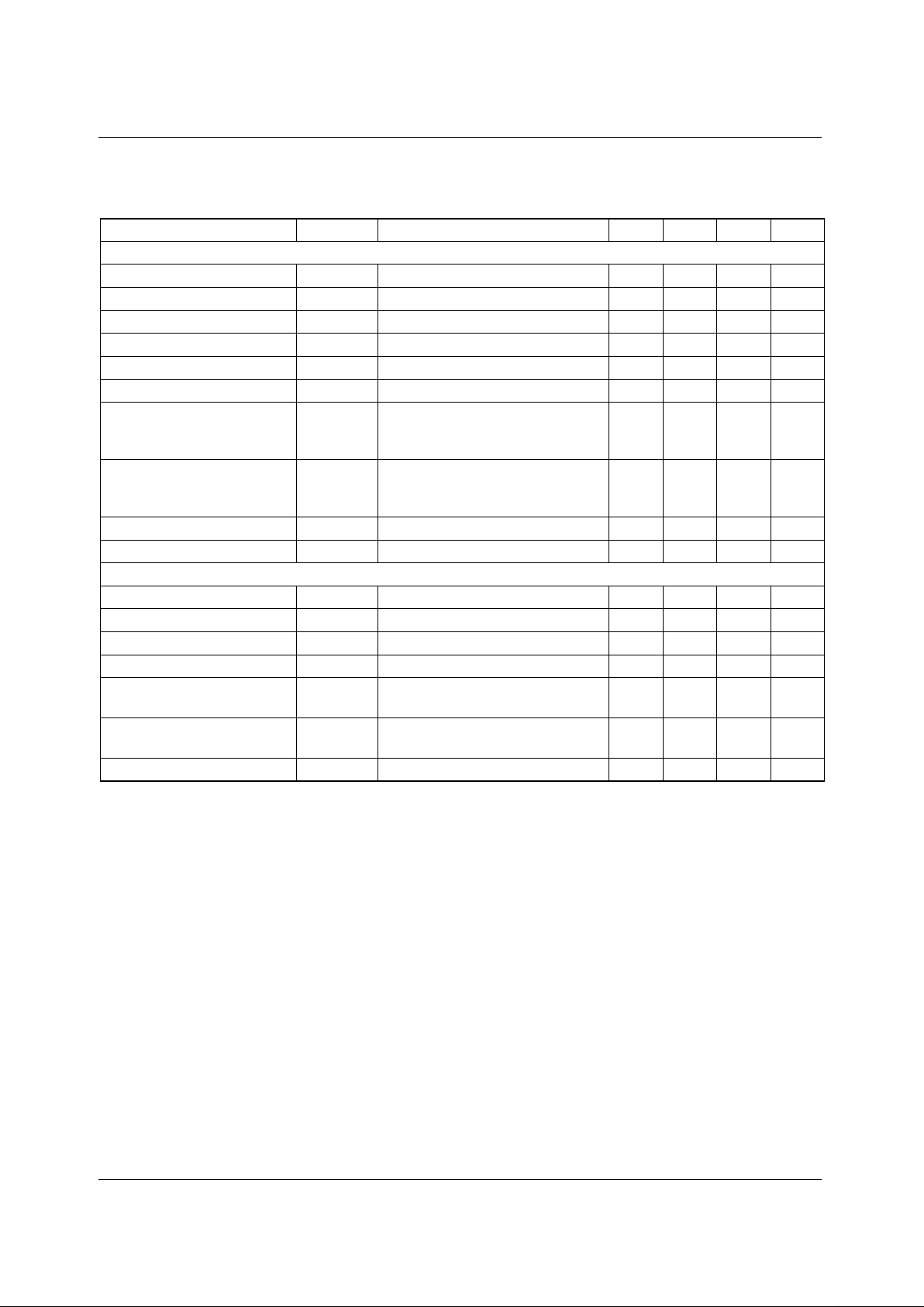
Electrical Characteristics
(Ta=25°C, V
CC1=VCC2
=5V, RL=8Ω)
Parameter Symbol Conditions Min. Typ. Max. Units
DRIVE CIRCUIT
Quiescent current 1 I
CC1
No load, Mute off - 15 20 mA
Quiescent current 2 I
CC2
No load, Mute on - - 500 uA
Output offset voltage 1 V
OO1
CH 1, CH 4 −70 0 70 mA
Output offset voltage 2 V
OO2
CH 2, CH 3 −90 - 90 mV
Max.output amplitude 1 V
OM1
CH 1, CH 4 3 4.2 - V
Max.output amplitude 2 V
OM2
CH 2, CH 3 (RL=24Ω) 8 10.4 - V
Voltage gain 1 G
VC1
VIN=0.1V
RMS
, 1kHz, sinewave.
Input OP-amp
→ Buffer CH 1, CH 4
10 12.0 14 dB
Voltage gain 2 G
VC2
VIN=0.1V
RMS
, 1kHz, sinewave.
Input OP-amp
→ Buffer CH 2, CH 3
16 18 20 dB
Mute on voltage V
Mon
-2.0--V
Mute off voltage V
Moff
---0.5V
INPUT OP-AMP CIRCUIT
Input offset voltage V
OFOP
- −10 0 10 mV
Input bias current I
BOP
- - - 300 nA
High level output voltage V
OHOP
- 10 10.9 - V
Low level output voltage V
OLOP
--1.11.8V
Output driving current sink I
SINK
Input op-amp output
→ V
CC
& 1.2kΩ
1--mA
Output driving current source I
SOURCE
Input op-amp output
→ GND & 1.2kΩ
1--mA
Slew rate SR 100kHz square-wave 2Vp-p output - 1 - V / µs
Page 8
KA3012D
8
Application Information
1. MUTE
• When the voltage level of the mute pin is above 2V, the mute circuit is activated so that the output circuit will be
muted.
• When the mute pin #9 is open or the voltage of the mute pin #9 is below 0.5V, the mute circuit is deactivated and the output
circuit operates normally.
• When the mute circuit is activated, the voltage level of output pins becomes 1/2V
CC
(approximately).
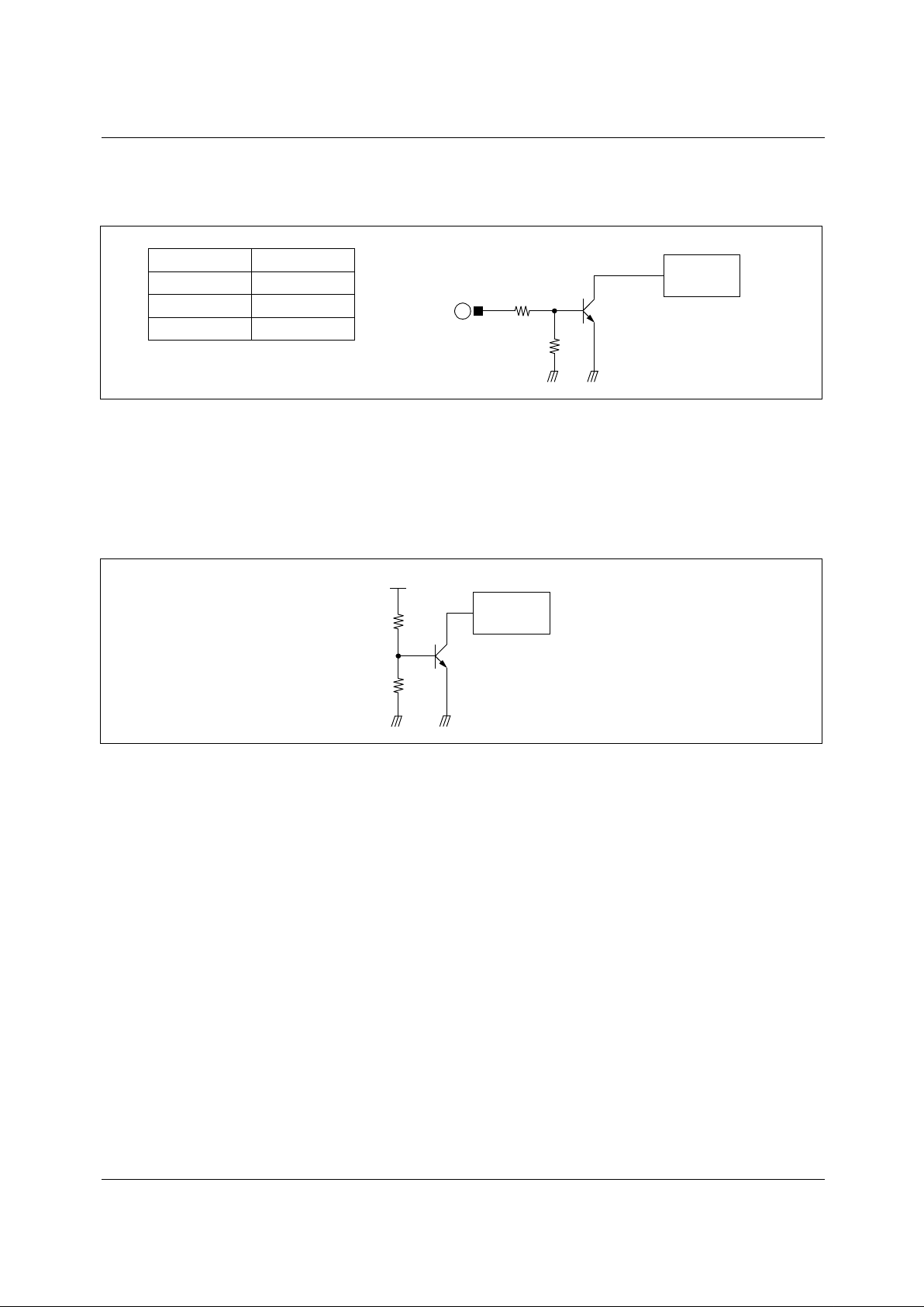
2. TSD (THERMAL SHUTDOWN)
• If the chip temperature rises above 175°C, then the TSD (Thermal shutdown) circuit is activated and the output circuit is
muted.
•The V
REF BG
is the output voltage of the band-gap-referenced bias in circuit and acts as the input voltage of the TSD
circuit.
• The base-emitter voltage of the TR,Q11 is designed to turn-on at 460mA.
V
BE
= V
REF BG
× R12 / (R11 + R12)=460m V
• When the chip temperature rises up to 175°C, the turn-on vol t age of the Q11 drops down to 460mV. (Hysteresis: 25 °C) and
Q11 turns on so the output circuit is muted.
Pin #9 Mut e circuit
High Turn-on
Low Turn-off
Open Turn-off
9
Output driver
bias
V
REF BG
R11
R12
Q11
Output driver
bias
Page 9
KA3012D
9
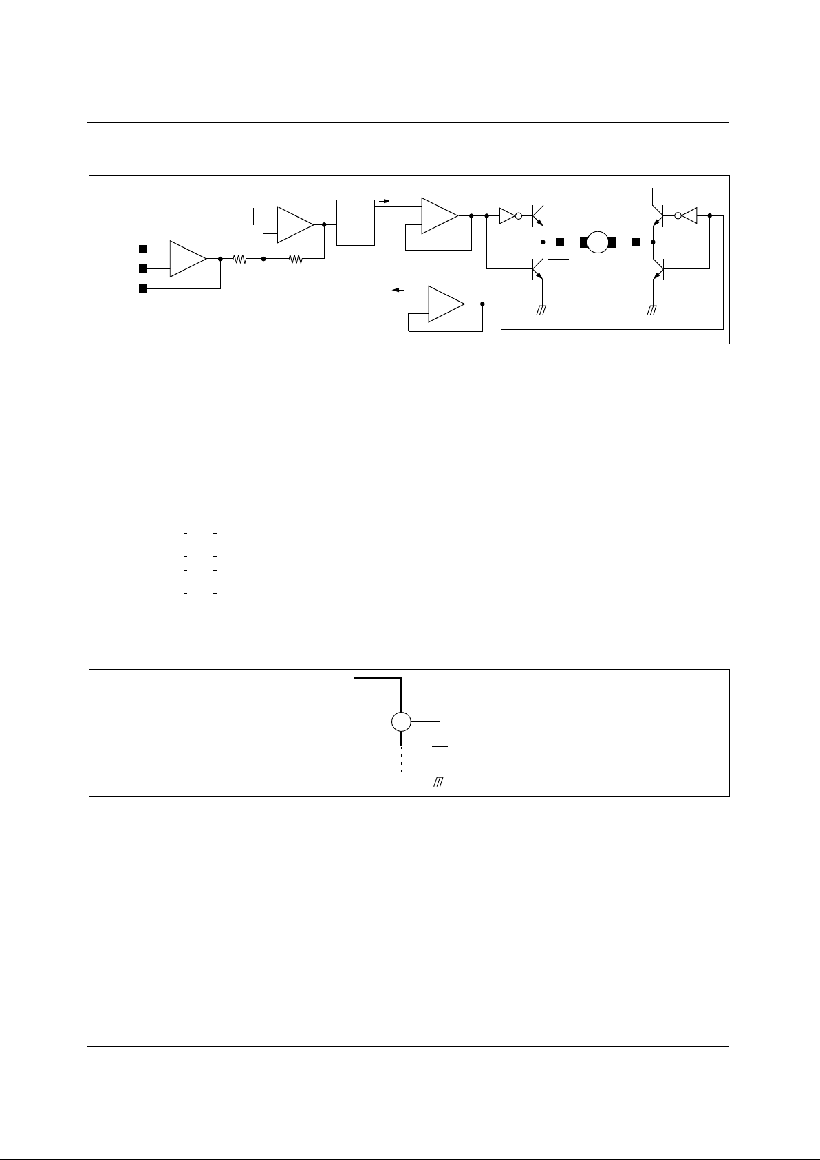
3. DRIVER
• The gain of pre-op. Amplifier can be changed by manipulating amp input resistor or feedback resistor.
• The voltage, V
REF
, is the reference voltage given by the bias voltage of the pin #6.
• The level shift produces the current due to the difference between the pre amp output signal and the arbitrary reference
(bias) signal. (The current produced as +∆I and −∆I is fed into the driver buffer. (CH1/CH4)
The current produced as +2∆I and −2∆I is fed into the driver buffer. (CH2/CH3)
• Driver buffer drives the power TR of the output stage according to the state of the input signal.
• The output stage is the BTL driver and the motor is rotating in forward direction by operating TR Q1 and TR Q4.On the
other hand, if TR Q2 and TR Q3 is operating, the motor is rotating in reverse direction.
• When the output voltage of Pre-Amp (Pin 3, 12, 18, 25) is below the V
REF
, then the direction of the motor is in forward.
• When the output voltage of Pre-Amp (Pin 3, 12, 18, 25) is above the V
REF
, then the direction of the motor in reverse.
•The gain (A
V
) of the drive circuit is as follows.
4. CONNECT A BY-PASS CAPACITOR, 0.1µµµµF BETWEEN THE SUPPLY VOLTAGE SOURCE.
5. RADIATION FIN IS CONNECTING TO THE INTERNAL GND OF THE PACKAGE.
CONNECT THE FIN TO THE EXTERNAL GND.
+
−
+
−
+
−
10k
BIAS
(6 Pin)
10k
AMP
−∆I
+∆I
Buffer
Buffer
Q1
Q3
M
Q2
Q4
−∆V+∆V
CH-O
(1, 14,
16, 27 Pin)
CH-O
(2, 13,
17, 26 Pin)
+
−
Level
shift
AMP-I (+)
(5, 10, 20, 23 Pin)
AMP-I (−)
(4, 11, 19, 24 Pin)
AMP-O
(3, 12, 18, 25 Pin)
Pre-amp
AV20 log
4V
IN
V
IN
------------
12 dB() (CH1/CH4)==
A
V
20 log
4V
IN
V
IN
------------
18 dB() (CH1/CH4)==
7
104
V
CC1
Page 10
KA3012D
10
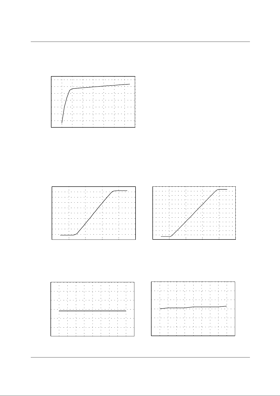
Typical Performa n ce Characteristics
VCC vs ICC (No load)
AMP-I (+) vs OUTPUT VOLTAGE
Figures can be obtained by changing of AMP-I (+) from 0V to 5V, shows the voltage difference between CH-O and CH-O.
(AMP-I (+) and AMP-O are shorted.)
VCC vs Gain
0
2
4
6
8
10
12
14
0246 810121416
ICC (mA)
VCC (V)
012 453
AMP-I (+)(V) AMP-I (+)(V)
Output Voltage Vom1(V)
-12
-10
-8
-6
-4
-2
0
2
4
6
8
10
12
0
12345
Output Voltage Vom1(V)
1. CH 1 and CH 4 (12dB) 2. CH 2 and CH 3 (18dB)
-5
-4
-3
-2
-1
0
1
2
3
4
5
VCC (V) VCC (V)
9
10
11
12
13
14
15
4
56789
011121314 4
56789
011121314
Gain1(dB)
Gain1(dB)
15
16
17
18
19
20
21
1. CH 1 and CH 4 (12dB) 2. CH 2 and CH 3 (18dB)
Page 11
KA3012D
11
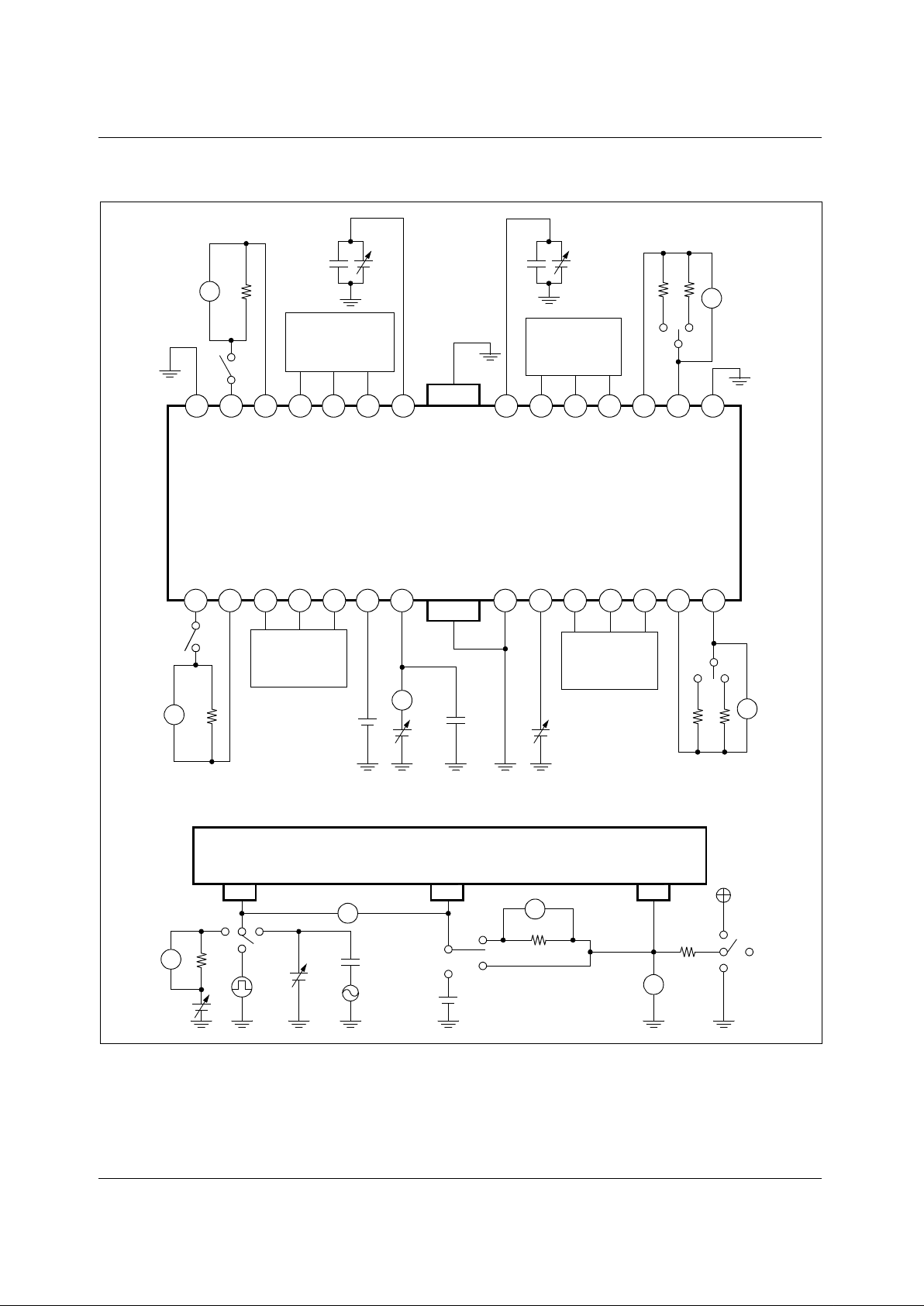
Test Circuits
V
V
V
A
V
V
V
V
V
1234567 891011121314
1516171819202122232425262728
KA3012D
SW4
R
L4
10µF
PV
CC1
OPOUT
OPIN (+)
OPIN (−)
SW3
OPIN (+)
OPIN (−)
OPOUT
PV
CC2
10µF
R
L3RL3
’
OPOUT
OPIN (−)
OPIN (+)
OPOUT
OPIN (−)
OPIN (+)
SW1
R
L1
SV
CC
10µF
Bias
2.5V
V
MUTE
SW2
R
L2
RL2’
12V
OPIN (+) OPIN (−)OPOUT
SW5
1
2
3
1MΩ
V
IN1
V
IN2
1.2kΩ
V
CC
SW7
1
2
3
SW6
V
IN3
V
IN5
10µF
1MΩ
2
3
1
V
IN4
Page 12
KA3012D
12
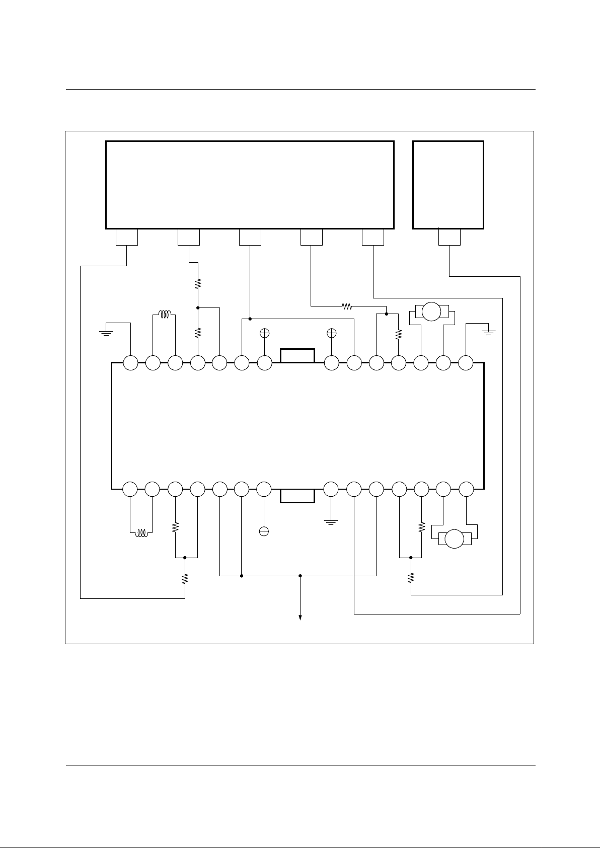
Typical Application Circuits
1234567 891011121314
1516171819202122232425262728
KA3012D
FOCUS TRACKING BIAS SLED
LOADING
(SPINDLE)
MUTE
SERVO PREA M P MICOM
10kΩ
10kΩ
10kΩ
10kΩ
M
M
10kΩ
10kΩ
10kΩ
10kΩ
BIAS
GND
GND
Page 13

KA3012D
12/1/00 0.0m 001
Stock#DSxxxxxxxx
2000 Fairchild Semiconductor International
LIFE SUPPORT POL I CY
FAIRCHILD’S PRODUCTS ARE NOT AUTHORIZED FOR USE AS CRITICAL COMPONENTS IN LIFE SUPPORT DEVICES
OR SYSTEMS WITHOUT THE EXPRESS WRITTEN APPROVAL OF THE PRESIDENT OF FAIRCHILD SEMICONDUCTOR
INTERNATIONAL. As used herein:
1. Life support devices or systems are devices or systems
which, (a) are intended for surgical implant into the body,
or (b) support or sustain life, and (c) whose failure to
perform when properly used in accordance with
instructions for use provided in the labeling, can be
reasonably expected to result in a significant injury of the
user.
2. A critical component in any component of a life support
device or sys tem whose failure to perform can be
reasonably expec ted to cause the failur e of the life support
device or system, or to affect its safety or effec tiveness.
www.fairchildsemi.com
DISCLAIMER
FAIRCHILD SEMICONDUCTOR RESERVES THE RIGHT TO MAKE CHANGES WITHOUT FURTHER NOTICE TO ANY
PRODUCTS HEREI N TO IMPROVE RELIABILITY, FUNCTION OR DES IGN. FAIRCHILD DOES NOT ASSUME ANY
LIABILITY ARISING OUT OF THE APPLICATION OR USE OF ANY PRODUCT OR CIRCUIT DESCRIBED HEREIN; NEITHER
DOES IT CONVEY ANY LICENSE UNDER ITS PATENT RIGHTS, NOR THE RI GHTS OF OTHERS.
 Loading...